EP0221401B1 - Rotierende Datenübertragungsvorrichtung - Google Patents
Rotierende Datenübertragungsvorrichtung Download PDFInfo
- Publication number
- EP0221401B1 EP0221401B1 EP86114150A EP86114150A EP0221401B1 EP 0221401 B1 EP0221401 B1 EP 0221401B1 EP 86114150 A EP86114150 A EP 86114150A EP 86114150 A EP86114150 A EP 86114150A EP 0221401 B1 EP0221401 B1 EP 0221401B1
- Authority
- EP
- European Patent Office
- Prior art keywords
- data transmission
- transmitters
- receivers
- waveguide
- rotor
- Prior art date
- Legal status (The legal status is an assumption and is not a legal conclusion. Google has not performed a legal analysis and makes no representation as to the accuracy of the status listed.)
- Expired - Lifetime
Links
- 230000005540 biological transmission Effects 0.000 title claims description 36
- 230000005855 radiation Effects 0.000 claims description 6
- 239000004020 conductor Substances 0.000 description 3
- 230000008878 coupling Effects 0.000 description 2
- 238000010168 coupling process Methods 0.000 description 2
- 238000005859 coupling reaction Methods 0.000 description 2
- 239000006096 absorbing agent Substances 0.000 description 1
- 238000010586 diagram Methods 0.000 description 1
- 230000005684 electric field Effects 0.000 description 1
- 230000001902 propagating effect Effects 0.000 description 1
Images

Classifications
-
- A—HUMAN NECESSITIES
- A61—MEDICAL OR VETERINARY SCIENCE; HYGIENE
- A61B—DIAGNOSIS; SURGERY; IDENTIFICATION
- A61B6/00—Apparatus or devices for radiation diagnosis; Apparatus or devices for radiation diagnosis combined with radiation therapy equipment
- A61B6/56—Details of data transmission or power supply, e.g. use of slip rings
-
- H—ELECTRICITY
- H01—ELECTRIC ELEMENTS
- H01P—WAVEGUIDES; RESONATORS, LINES, OR OTHER DEVICES OF THE WAVEGUIDE TYPE
- H01P1/00—Auxiliary devices
- H01P1/06—Movable joints, e.g. rotating joints
- H01P1/062—Movable joints, e.g. rotating joints the relative movement being a rotation
- H01P1/066—Movable joints, e.g. rotating joints the relative movement being a rotation with an unlimited angle of rotation
- H01P1/068—Movable joints, e.g. rotating joints the relative movement being a rotation with an unlimited angle of rotation the energy being transmitted in at least one ring-shaped transmission line located around the axis of rotation, e.g. "around the mast" rotary joint
Definitions
- the invention relates to a data transmission device for data transmission between a rotor and a stator, in which a number of transmitters is arranged on the rotor or the stator and a different number of receivers is arranged on the stator or rotor, the respective numbers being selected in this way that a continuous data transmission takes place between the rotor and the stator, and in which an annular data transmission path is arranged between the transmitters and the receivers.
- DE-OS 28 46 526 describes a data transmission device of this type, in which the rotor is formed by the turntable of a computer tomograph on which an X-ray emitter and a radiation detector are arranged.
- the data generated by the detector is transmitted with the aid of a ring of light-conducting material which is curved around the center of rotation and on whose surface a light source emits which emits light signals corresponding to the signals to be transmitted.
- the ring transmits the incident light over its entire circumference and has a coupling point at which a light receiver is arranged on the fixed part.
- the invention is based on the object of designing a rotating data transmission device of the type mentioned at the outset in such a way that trouble-free data transmission, in particular high data rates, is ensured with a simple structure, with several transmission channels being formed with a single data transmission path in which information is also transmitted in both directions can be.
- the data transmission path is divided symmetrically into a number of separate individual sections, and in that the transmitter and receiver are arranged such that the simultaneous transmission of a plurality of information between a plurality of transmitter-receiver pairs takes place.
- An embodiment of the data transmission device which is particularly suitable for use in a computer tomograph for the transmission of high data rates, is obtained in that the transmitters modulated high-frequency waves, e.g. electromagnetic type, couple into the respectively assigned waveguide, and that the receivers are designed to accept the waves guided in the waveguides. With the help of the high-frequency waves propagating in the waveguide, a high data rate is transmitted.
- modulated high-frequency waves e.g. electromagnetic type
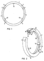
- the waveguide 1 shows a waveguide 1, on which two microwave transmitters 2, 3 are attached.
- the microwave transmitters 2, 3 radiate into the waveguide 1 in the direction indicated by the arrows 4, 5.
- Four wave sumps 6 to 9 divide the waveguide 1 into four sections of equal length. In the example, it is assumed that the waveguide 1 rotates with the transmitters 2, 3 and that the data transmission from the two transmitters 2, 3 to three stationary receivers 10, 11, 12, each offset by 120 °, takes place.
- the other two of the four waveguide sections formed by the wave sumps can be used for a second data transmission path.
- FIG. 2 shows that the waveguide 1 is designed as a ring with a rectangular cross section, which has a slot 13 on its inside.
- the waveguide 1 When the waveguide 1 rotates, it moves relative to the three fixed receivers 10, 11, 12 which, with conductors, of which the conductor 17 of the receiver 10 is shown, protrude through the slot 13 into the interior 15 of the waveguide 1 and there scan the microwave that is spreading.
- the wave sumps 6, 7, 8, 9 can be formed in a known manner by adapted absorber constructors in the interior of the waveguide 1.
- FIG. 3 schematically shows the radiation detector 18 of a computer tomograph, which detects the X-ray beam 21 which passes through a patient 19 shown in cross section and extends from the focus 20 of an X-ray emitter.
- the radiation detector 18 consists of a series of, for example, 512 detector elements and the data of these detector elements are fed to a modulator 22 which transmits the waves of a microwave source 23 to the respective ones Data modulated accordingly.
- the modulated microwaves are fed to the two transmitters 2, 3 of the waveguide 1 via a distributor 24 and are fed to a computer 29 by the receivers 10 to 12 demodulators 25, 26, 27 and from there via a changeover switch 28, for example a multiplexer.
- the computer 29 calculates a cross-sectional image of the patient 19 from the transmitted data that are supplied when the scanning unit 18, 20 rotates around the patient 19.
- the rotating part comprises the waveguide 1, to which the x-ray emitter and the radiation detector 18 are firmly connected. These parts are only shown separately in FIG. 3 for the sake of clarity.
Landscapes
- Life Sciences & Earth Sciences (AREA)
- Engineering & Computer Science (AREA)
- Health & Medical Sciences (AREA)
- Medical Informatics (AREA)
- Biomedical Technology (AREA)
- Surgery (AREA)
- High Energy & Nuclear Physics (AREA)
- Physics & Mathematics (AREA)
- Nuclear Medicine, Radiotherapy & Molecular Imaging (AREA)
- Optics & Photonics (AREA)
- Pathology (AREA)
- Radiology & Medical Imaging (AREA)
- Computer Networks & Wireless Communication (AREA)
- Heart & Thoracic Surgery (AREA)
- Molecular Biology (AREA)
- Biophysics (AREA)
- Animal Behavior & Ethology (AREA)
- General Health & Medical Sciences (AREA)
- Public Health (AREA)
- Veterinary Medicine (AREA)
- Apparatus For Radiation Diagnosis (AREA)
- Arrangements For Transmission Of Measured Signals (AREA)
- Cable Transmission Systems, Equalization Of Radio And Reduction Of Echo (AREA)
- Radar Systems Or Details Thereof (AREA)
- Waveguide Connection Structure (AREA)
Applications Claiming Priority (2)
| Application Number | Priority Date | Filing Date | Title |
|---|---|---|---|
| DE3538035 | 1985-10-25 | ||
| DE19853538035 DE3538035A1 (de) | 1985-10-25 | 1985-10-25 | Rotierende datenuebertragungsvorrichtung |
Publications (2)
| Publication Number | Publication Date |
|---|---|
| EP0221401A1 EP0221401A1 (de) | 1987-05-13 |
| EP0221401B1 true EP0221401B1 (de) | 1991-09-11 |
Family
ID=6284474
Family Applications (1)
| Application Number | Title | Priority Date | Filing Date |
|---|---|---|---|
| EP86114150A Expired - Lifetime EP0221401B1 (de) | 1985-10-25 | 1986-10-13 | Rotierende Datenübertragungsvorrichtung |
Country Status (4)
| Country | Link |
|---|---|
| US (1) | US4796183A (enExample) |
| EP (1) | EP0221401B1 (enExample) |
| JP (1) | JPS6271938U (enExample) |
| DE (2) | DE3538035A1 (enExample) |
Families Citing this family (43)
| Publication number | Priority date | Publication date | Assignee | Title |
|---|---|---|---|---|
| JPH062131B2 (ja) * | 1988-06-03 | 1994-01-12 | 株式会社東芝 | X線ctスキヤナ |
| US4912735A (en) * | 1988-07-18 | 1990-03-27 | Elscint Ltd. | Power transfer apparatus particularly for CT scanner |
| US5157393A (en) * | 1989-02-28 | 1992-10-20 | Kabushiki Kaisha Toshiba | Communication system for transmitting data between a transmitting antenna utilizing leaky coaxial cable and a receive antenna in relative movement to one another |
| US5140696A (en) * | 1989-02-28 | 1992-08-18 | Kabushiki Kaisha Toshiba | Communication system for transmitting data between a transmitting antenna utilizing strip-line transmission line and a receive antenna in relative movement to one another |
| US5010254A (en) * | 1989-04-05 | 1991-04-23 | Kabushiki Kaisha Toshiba | System for communicating energy between relatively moving devices |
| IL90853A0 (en) * | 1989-07-03 | 1990-02-09 | Elscint Ltd | Optical communication link |
| JPH03205901A (ja) * | 1989-10-26 | 1991-09-09 | Toshiba Corp | 電気機械装置 |
| US5018174A (en) * | 1989-11-20 | 1991-05-21 | General Electric Company | High speed communication apparatus for computerized axial tomography (CAT) scanners |
| US5231653A (en) * | 1990-01-11 | 1993-07-27 | Siemens Aktiengesellschaft | X-ray diagnostics installation |
| DE4116381C1 (enExample) * | 1991-05-18 | 1992-07-02 | Philips Patentverwaltung Gmbh, 2000 Hamburg, De | |
| IL98421A (en) * | 1991-06-09 | 1995-07-31 | Elscint Ltd | Optical communication link |
| US5229871A (en) * | 1991-08-29 | 1993-07-20 | Kabushiki Kaisha Toshiba Corporation | Optical data link for communicating data between a stationary member and a rotating member and an X-ray computer tomography apparatus incorporating the same |
| DE69310965T2 (de) * | 1992-03-16 | 1997-12-11 | Eastman Kodak Co | Vorrichtung zum Übertragen von elektrischen Signalen und Versorungsleistung zu einem Datenspeicher einer Kassette. |
| US5454022A (en) * | 1993-03-26 | 1995-09-26 | Eastman Kodak Company | Method of taking X-ray images with a CCD image sensor, and a CCD image sensor system |
| DE4421616C2 (de) * | 1993-08-25 | 2001-05-23 | Schleifring Und App Bau Gmbh | Vorrichtung zur optischen Signalübertragung zwischen bewegten Teilen |
| US5577026A (en) * | 1993-12-28 | 1996-11-19 | Analogic Corporation | Apparatus for transferring data to and from a moving device |
| US5600697A (en) * | 1995-03-20 | 1997-02-04 | General Electric Company | Transmission line using a power combiner for high data rate communication in a computerized tomography system |
| DE19716838A1 (de) * | 1997-04-22 | 1998-10-29 | Deutsche Telekom Ag | Anordnung zum Senden und Empfangen optischer Signale |
| US6104849A (en) * | 1997-10-02 | 2000-08-15 | Litton Systems, Inc. | Fiber optic rotary joint |
| DE19815389A1 (de) * | 1998-04-06 | 1999-10-07 | Matthias Krause | Anordnung zur Übertragung von Daten zwischen Kommunikationsteilnehmern |
| US6396613B1 (en) * | 1998-12-22 | 2002-05-28 | General Electric Company | Optical high speed communications for a computed tomography x-ray machine |
| JP4495794B2 (ja) * | 1999-04-28 | 2010-07-07 | 株式会社東芝 | 信号伝送装置及びx線ctスキャナ |
| JP3612264B2 (ja) * | 2000-07-18 | 2005-01-19 | 株式会社東芝 | 回転体・固定体間光伝送装置 |
| US6385367B1 (en) * | 2000-07-31 | 2002-05-07 | Northrop Grumman Corporation | Parallel data transmission through segmented waveguides of large diameter |
| US6453088B1 (en) | 2000-07-31 | 2002-09-17 | Litton Systems, Inc. | Segmented waveguide for large diameter fiber optic rotary joint |
| US6782207B1 (en) * | 2001-04-27 | 2004-08-24 | Research Foundation Of The University Of Central Florida, Incorpoated | Narrow band transmitting-receiving telescope system |
| US7027737B2 (en) * | 2002-09-26 | 2006-04-11 | Siemens Aktiengesellschaft | Method and apparatus for transmitting data from a rotary part to a stationary part of a data generating system |
| EP1549934B1 (en) * | 2002-10-02 | 2011-01-19 | Reveal Imaging Technologies, Inc. | Folded array ct baggage scanner |
| US7224765B2 (en) * | 2002-10-02 | 2007-05-29 | Reveal Imaging Technologies, Inc. | Computed tomography system |
| DE10319248B4 (de) | 2003-04-28 | 2010-11-25 | Schleifring Und Apparatebau Gmbh | Schleifring mit verlustbehafteter Leiterbahn |
| US7039154B1 (en) * | 2003-10-02 | 2006-05-02 | Reveal Imaging Technologies, Inc. | Folded array CT baggage scanner |
| JP2007508887A (ja) * | 2003-10-23 | 2007-04-12 | コーニンクレッカ フィリップス エレクトロニクス エヌ ヴィ | 光電子データ転送を用いるコンピュータ断層撮影装置 |
| DE102005010845A1 (de) * | 2004-12-15 | 2006-07-06 | Schleifring Und Apparatebau Gmbh | Optischer Drehübertrager mit aktiver Terminierung |
| US20080037703A1 (en) * | 2006-08-09 | 2008-02-14 | Digimd Corporation | Three dimensional breast imaging |
| CN101978552B (zh) * | 2008-03-19 | 2014-06-04 | 皇家飞利浦电子股份有限公司 | 波导及具有波导的计算机断层摄影系统 |
| JP2011521700A (ja) * | 2008-06-02 | 2011-07-28 | コーニンクレッカ フィリップス エレクトロニクス エヌ ヴィ | データ送信用のコンピュータ断層撮影ガントリーに関するデバイス |
| GB201317637D0 (en) | 2013-10-04 | 2013-11-20 | Johnson Matthey Plc | Data Transfer Apparatus |
| US9968328B2 (en) * | 2015-02-17 | 2018-05-15 | General Electric Company | Wireless data transfer in a deterministic rotating system |
| US10326561B2 (en) * | 2015-06-24 | 2019-06-18 | Toshiba Medical Systems Corporation | Mirror-ring assembly for bi-directional optical communication between a rotor and a stator |
| EP3391395A4 (en) * | 2015-12-11 | 2019-06-19 | Oceaneering International Inc. | RING WITH SENSORS HIGH DATA RATE |
| WO2019180215A1 (en) | 2018-03-22 | 2019-09-26 | Schleifring Gmbh | Rotary joint with dielectric waveguide |
| EP3977644B1 (de) | 2019-05-29 | 2024-12-04 | Sew-Eurodrive GmbH & Co. KG | System, insbesondere anlage, mit einem mobilteil und einem einen schirm aufnehmenden aufnahmeteil |
| DE202023105653U1 (de) * | 2023-09-28 | 2025-01-09 | Conductix-Wampfler Gmbh | Kommunikationsvorrichtung |
Family Cites Families (11)
| Publication number | Priority date | Publication date | Assignee | Title |
|---|---|---|---|---|
| GB1233553A (enExample) * | 1967-07-14 | 1971-05-26 | ||
| JPS5826217B2 (ja) * | 1975-06-06 | 1983-06-01 | 三菱電機株式会社 | シンゴウデンソウソウチ |
| DE2846526A1 (de) * | 1978-10-25 | 1980-05-08 | Siemens Ag | Vorrichtung zum uebertragen von signalen |
| DE2855379A1 (de) * | 1978-12-21 | 1980-07-03 | Siemens Ag | Roentgendiagnostikgeraet fuer die erzeugung von schichtbildern eines aufnahmeobjektes |
| US4427983A (en) * | 1981-12-24 | 1984-01-24 | International Telephone & Telegraph Corporation | Lossless annular rotary RF coupler |
| FR2522884A1 (fr) * | 1982-03-04 | 1983-09-09 | Messerschmitt Boelkow Blohm | Joint tournant haute frequence |
| DE3209906A1 (de) * | 1982-03-18 | 1984-02-02 | ANT Nachrichtentechnik GmbH, 7150 Backnang | Hohlleiter-drehkupplung |
| DE3215377A1 (de) * | 1982-04-24 | 1983-10-27 | Philips Patentverwaltung Gmbh, 2000 Hamburg | Vorrichtung fuer die mikrowellenuebertragung zwischen zwei relativ zueinander drehbaren teilen |
| JPS6031734A (ja) * | 1983-07-29 | 1985-02-18 | 株式会社東芝 | X線gtスキヤナ |
| DE3331722A1 (de) * | 1983-09-02 | 1985-03-21 | Philips Patentverwaltung Gmbh, 2000 Hamburg | Vorrichtung zum uebertragen elektrischer signale zwischen relativ zueinander beweglichen teilen |
| JPS61105902A (ja) * | 1984-10-30 | 1986-05-24 | Sony Corp | 回転結合器 |
-
1985
- 1985-10-25 DE DE19853538035 patent/DE3538035A1/de not_active Withdrawn
-
1986
- 1986-10-02 US US06/914,236 patent/US4796183A/en not_active Expired - Fee Related
- 1986-10-13 DE DE8686114150T patent/DE3681402D1/de not_active Expired - Lifetime
- 1986-10-13 EP EP86114150A patent/EP0221401B1/de not_active Expired - Lifetime
- 1986-10-24 JP JP1986163477U patent/JPS6271938U/ja active Pending
Also Published As
| Publication number | Publication date |
|---|---|
| DE3538035A1 (de) | 1987-04-30 |
| EP0221401A1 (de) | 1987-05-13 |
| US4796183A (en) | 1989-01-03 |
| DE3681402D1 (de) | 1991-10-17 |
| JPS6271938U (enExample) | 1987-05-08 |
Similar Documents
| Publication | Publication Date | Title |
|---|---|---|
| EP0221401B1 (de) | Rotierende Datenübertragungsvorrichtung | |
| DE2844776C2 (de) | Sendersystem für ein Kommunikationssystem mit beweglichen Teilnehmern | |
| DE69835514T2 (de) | Mikrowellenantennensystem und verfahren | |
| DE19533820B4 (de) | Differentiell betriebene Übertragungsleitung für eine Kommunikation mit hoher Datenrate in einem Computer-Tomographie-System | |
| EP0093468B1 (de) | Vorrichtung für die Mikrowellenübertragung zwischen zwei relativ zueinander drehbaren Teilen | |
| DE4322863C2 (de) | Mobilfunkantennenanlage | |
| EP0610989A2 (de) | Funksystem mit Raumdiversitysender/-empfänger | |
| EP0829922A2 (de) | Phasengesteuerte Antenne | |
| DE4006007A1 (de) | Antennensystem fuer rotierende plattform | |
| DE69211330T2 (de) | Funksende- und -empfangsanordnung | |
| DE2744212C2 (de) | Duplex-Sende-Empfangseinrichtung | |
| DE1942678B2 (de) | Speiseanordnung für eine mit mehreren Wellentypen arbeitende Antenne | |
| DE2801142C2 (de) | Verfahren zur Navigation und Standortbestimmung eines Fahrzeuges | |
| DE1292205B (de) | Drahtloses Nachrichten-UEbermittlungssystem zur Nachrichtenuebertragung zwischen einem sich entlang einer Spur bewegenden Fahrzeug und einer feststehenden Station | |
| DE3331722A1 (de) | Vorrichtung zum uebertragen elektrischer signale zwischen relativ zueinander beweglichen teilen | |
| DE3231564A1 (de) | Funksystem | |
| EP0567888A2 (de) | Kommunikationssystem zur Datenübertragung von einem bewegten Fahrzeug auf eine ortsfeste Bake | |
| EP1139491B1 (de) | Abstrahlendes koaxiales Hochfrequenzkabel | |
| DE69316173T2 (de) | Fernrückschleifsystem für Funkübertragungs-Sendeempfänger | |
| DE8530295U1 (de) | Rotierende Datenübertragungsvorrichtung | |
| DE2660472C2 (de) | Kaskaden-Filtersystem, bei dem zwei Schwingungsquellen mit unterschiedlichen Frequenzen abwechselnd oder gleichzeitig auf einen gemeinsamen Verbraucher arbeiten | |
| DE69011295T2 (de) | Landungshilfssystem vom Typ MLS mit zentralen Mitteln zur Erzeugung von Mikrowellen. | |
| EP0012917A1 (de) | Homodyn-Übertragungssystem | |
| DE1441799B2 (de) | Leitungsnetzwerk zum einfuegen in eine antennenleitung | |
| EP0765095A2 (de) | Verfahren zur Zuteilung funktechnischer Ressourcen auf mehrere Übertragungseinrichtungen einer Basisstation innerhalb eines funktechnischen Kommunikationssystems |
Legal Events
| Date | Code | Title | Description |
|---|---|---|---|
| PUAI | Public reference made under article 153(3) epc to a published international application that has entered the european phase |
Free format text: ORIGINAL CODE: 0009012 |
|
| AK | Designated contracting states |
Kind code of ref document: A1 Designated state(s): DE FR |
|
| 17P | Request for examination filed |
Effective date: 19870604 |
|
| 17Q | First examination report despatched |
Effective date: 19890804 |
|
| GRAA | (expected) grant |
Free format text: ORIGINAL CODE: 0009210 |
|
| AK | Designated contracting states |
Kind code of ref document: B1 Designated state(s): DE FR |
|
| REF | Corresponds to: |
Ref document number: 3681402 Country of ref document: DE Date of ref document: 19911017 |
|
| ET | Fr: translation filed | ||
| PLBE | No opposition filed within time limit |
Free format text: ORIGINAL CODE: 0009261 |
|
| STAA | Information on the status of an ep patent application or granted ep patent |
Free format text: STATUS: NO OPPOSITION FILED WITHIN TIME LIMIT |
|
| 26N | No opposition filed | ||
| PGFP | Annual fee paid to national office [announced via postgrant information from national office to epo] |
Ref country code: FR Payment date: 19921016 Year of fee payment: 7 |
|
| PGFP | Annual fee paid to national office [announced via postgrant information from national office to epo] |
Ref country code: DE Payment date: 19931216 Year of fee payment: 8 |
|
| PG25 | Lapsed in a contracting state [announced via postgrant information from national office to epo] |
Ref country code: FR Effective date: 19940630 |
|
| REG | Reference to a national code |
Ref country code: FR Ref legal event code: ST |
|
| PG25 | Lapsed in a contracting state [announced via postgrant information from national office to epo] |
Ref country code: DE Effective date: 19950701 |