EP0220681B1 - Installation pour fractionner et broyer des matériaux fragiles et mouillés - Google Patents
Installation pour fractionner et broyer des matériaux fragiles et mouillés Download PDFInfo
- Publication number
- EP0220681B1 EP0220681B1 EP86114720A EP86114720A EP0220681B1 EP 0220681 B1 EP0220681 B1 EP 0220681B1 EP 86114720 A EP86114720 A EP 86114720A EP 86114720 A EP86114720 A EP 86114720A EP 0220681 B1 EP0220681 B1 EP 0220681B1
- Authority
- EP
- European Patent Office
- Prior art keywords
- line
- discharge
- mill
- impact hammer
- hammer mill
- Prior art date
- Legal status (The legal status is an assumption and is not a legal conclusion. Google has not performed a legal analysis and makes no representation as to the accuracy of the status listed.)
- Expired - Lifetime
Links
Images

Classifications
-
- B—PERFORMING OPERATIONS; TRANSPORTING
- B02—CRUSHING, PULVERISING, OR DISINTEGRATING; PREPARATORY TREATMENT OF GRAIN FOR MILLING
- B02C—CRUSHING, PULVERISING, OR DISINTEGRATING IN GENERAL; MILLING GRAIN
- B02C21/00—Disintegrating plant with or without drying of the material
-
- B—PERFORMING OPERATIONS; TRANSPORTING
- B02—CRUSHING, PULVERISING, OR DISINTEGRATING; PREPARATORY TREATMENT OF GRAIN FOR MILLING
- B02C—CRUSHING, PULVERISING, OR DISINTEGRATING IN GENERAL; MILLING GRAIN
- B02C23/00—Auxiliary methods or auxiliary devices or accessories specially adapted for crushing or disintegrating not provided for in preceding groups or not specially adapted to apparatus covered by a single preceding group
- B02C23/18—Adding fluid, other than for crushing or disintegrating by fluid energy
Definitions
- the invention relates to a device for comminution and grinding and drying (grinding drying) of moist, brittle regrind, such as starting material for cement raw meal, ore, coal or the like, with an impact hammer mill, at the inlet of which the supply of the moist regrind and a hot gas line and others Good discharge is connected to a riser designed as a current dryer, which leads to a classifier, whose discharge line for the coarse material (grit) is connected to the task of a comminution device.
- moist, brittle regrind such as starting material for cement raw meal, ore, coal or the like
- an impact hammer mill at the inlet of which the supply of the moist regrind and a hot gas line and others Good discharge is connected to a riser designed as a current dryer, which leads to a classifier, whose discharge line for the coarse material (grit) is connected to the task of a comminution device.
- roller press operated with a high pressing force of in particular more than 2 t / cm roller length produces agglomerates (Schülpen) during material pressing, the grindability of which is considerably improved compared to unpressed material, so that the known two-stage size reduction leads overall to a significant reduction in the specific energy requirement .
- the individual material particles are crushed in a material bed, that is, in a material bed compressed between two surfaces, so that in the first stage one speaks of the so-called material bed comminution.
- the invention is based on the object of making the energy-saving high-pressure roller press with material bed comminution usable even in the mill drying of moist goods, and of ensuring that the high-pressure roller press used receives a feed material with a reasonably uniform grain size distribution, even if the grain size of the fresh moist one Starting material over a wide range of, for example, 0 to 100 mm and also the humidity fluctuates over a wide range, which is actually the case, for example, with moist starting material for cement raw meal, without as previously at the beginning described grinding drying systems usually have to use a ball mill.
- the fresh, moist starting material to be crushed is not fed to the high-pressure roller press, but to the other crushing machine, namely the impact hammer which feed material with a grain size distribution of 0 to approx. 80 mm can be easily shredded and which, seen in the regrind stream, is followed by the high-pressure roller press.
- the device according to the invention with an integrated high-pressure roller press it is therefore proposed for the first time to bypass the high-pressure roller press with the fresh starting material.
- the high-pressure roller press used can always be operated uniformly with the optimally set roller pressing force of, for example, 6 to 9 t / cm roller length, free of shock loads.
- the high-pressure roller press as it is switched on in the mill-drying device according to the invention, runs very quietly, which also means that the savings in comminution energy which can be achieved with the material bed comminution can actually take full effect when the starting material is moist.
- the good discharge of the roller press is connected with the good inlet and / or with the good discharge of the impact hammer mill. If the roller press discharge, which usually consists of agglomerates (Schülpen), together with the fresh starting material is fed to the inlet of the impact gas mill through which hot gas flows, the easily crumbling agglomerates of the roller press are removed from the Impact hammer mill deagglomerated practically without additional operating costs. If the roller press discharge bypasses the impact hammer mill and if it is introduced into its discharge, the crop agglomerates are deagglomerated in the riser arranged between impact hammer mill and sifter and / or in a corresponding crop entry lock such as a tubular screw.
- the roller press discharge which usually consists of agglomerates (Schülpen)
- the crop agglomerates are deagglomerated in the riser arranged between impact hammer mill and sifter and / or in a corresponding crop entry lock such as a tubular screw.
- the invention is particularly well applicable in the milling drying of fresh, moist starting material, for example starting material for cement raw meal.
- a hot gas line is connected to the inlet of the impact hammer mill equipped with a closed bottom, and the riser arranged between the discharge of the impact hammer mill and the classifier is designed as a current dryer.
- the coarse sifting material (grit) returned from the sifter to the high-pressure roller press has dried to such an extent that the material bed comminution of this sifting coarse material in the nip of the roller press is not hindered by the low residual moisture which may still be present.
- a characteristic of the mill-drying plant according to the invention for comminuting and grinding moist material is, above all, that the tube mill or ball mill which has always been used in mill-drying systems and which is characterized by very low energy utilization is no longer present, but rather by the principle of commodity bed comminution operated high-pressure roller press is replaced, which results in a significant reduction in investment costs and, above all, the specific energy requirement of the entire mill drying system. It is also possible without difficulty to convert existing grinding drying systems into the grinding drying system according to the invention after removal of the tube mill or ball mill, in order to take advantage of the extraordinarily high energy savings when operating the grinding drying system according to the invention.
- FIG. 1 shows the flow diagram of a grinding drying plant according to the invention for grinding and drying moist starting material for the production of raw cement meal.
- the starting material pre-shredded by a primary crusher is given with a grain size distribution of 0 to about 80 mm and with a moisture of up to about 20% via the feed (10) to the feed end of a belt conveyor (11), weigh feeder or the like and via the discharge end of the conveyor and introduced, for example, via a material lock (12), double pendulum lock into the feed inlet (13) of an impact hammer mill (14) with a closed bottom.
- a hot gas line (15) which is indicated by a broken line, is connected to the inlet (13) of the mill (14).
- Exhaust gas from a preheater for cement raw meal from a cement clinker combustion plant, hot exhaust air from a cement clinker cooler and / or hot gas from another hot gas generator can be used as hot gas.
- the hot gas supplied via the line (15) flows through the impact hammer mill (14), in which the starting material is pre-comminuted and pre-dried.
- the discharge line (19) for the coarse material (grit) is connected via a conveyor (20) to the feed shaft (21) of a high-pressure roller press (22).
- the sifting coarse material (19) is placed above the roller gap arranged vertical shaft (21) in such a large quantity to the nip of the press (22) that the material to be shredded and drawn in between the rollers pushes the rollers apart and the particles of the feed material in the nip in a bed or in a collective or in a bed crush each other.
- the pressing force of the rollers of the roller press (22) pressing the material is more than 2 t / cm roller length, for example 6 to 9 t / cm.
- the feed chute can be arranged on a weighing device such as, for example, on pressure load cells (23) or the like.
- the material discharge (24) of the roller press (22) emerges from the nip further comminuted and partially agglomerated, that is to say pressed out into slugs which can be crumbled with the hands and which already reduce a considerable proportion of the fineness of the finished product (finished cement raw meal) Include particles.
- the discharge material (24) is shown in the drawing as a dotted line.
- the material to be discharged from the press (24) is connected via line (24a) to the material inlet (13) of the impact hammer mill (14) and / or via line (24b) (conveying member) to the riser (17).
- the press material to be discharged (24) reaches the impact hammer mill (14) via line (24a)
- this has at least three functions at the same time: it serves to pre-shred the fresh starting material (10), to dry the damp material and to deagglomerate and re-shred the agglomerates of the Press discharge material (24) before it reaches the riser (17) serving as a current dryer.
- a lock such as a tube screw (25).
- the material lock (25) serves on the one hand to deagglomerate the roller press discharge material (24b) and on the other hand to prevent the entry of false air into the riser (17), in which, due to the induced draft fan (26), there is a negative pressure of about 350 to 400 mm water column .
- the material discharge (24) of the roller press (22) is divided into two fractions by a classification screen, not shown, of which the fine fraction (24b) to the riser (17) and the coarse fraction (24a) to the material inlet (13) of the impact hammer mill (14).
- roller press discharge material introduced via the line (24b) directly into the riser (17) designed as a current dryer is not sufficiently deagglomerated when it enters the riser (17), this would be harmless because the larger grains or agglomerates contained in the Riser pipe (17) would initially not be transported pneumatically upwards, fall down and get into the impact hammer mill (14), where they are finally crushed to such an extent that they are suspended in the riser pipe (17) from the drying gas in suspension to Sifters (18) are worn.
- the fine material discharge line (27) of the classifier (18) leads to a separator such as a filter (28), separating cyclone or the like, which, via a conveyor (29), for example screw conveyor, the fine material as finished product (30), that is, dried and ground cement raw meal , separates from the sight gas stream or drying gas stream (31).
- a separator such as a filter (28), separating cyclone or the like, which, via a conveyor (29), for example screw conveyor, the fine material as finished product (30), that is, dried and ground cement raw meal , separates from the sight gas stream or drying gas stream (31).
- the exhaust pipe (31) after separation of the finished product (30) via a branch line (32) with the hot gas line (15) connected to the product inlet (13) of the impact hammer mill and / or via a branch line (33) with the to the product discharge (16) Impact hammer mill (14) connected riser (17) in connection.
- Gas quantity throttling elements still shown in the gas-carrying lines of the drawing are not provided
- the specific energy requirement based on the finished product is on average about 1.5 kWh / t for the impact hammer mill and about 12 kWh / t for the ball mill.
- the specific energy requirement for the impact hammer mill is approximately 1.5 to 5 kWh / t and for the roller press approximately 6 kWh / t in the grinding drying system according to the invention with an upstream impact hammer mill and a downstream high-pressure roller press.
- the energy savings in kWh / t are higher the poorer the grindability of the starting material to be ground.
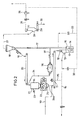
- FIG. 2 shows the flow diagram of a grinding drying system according to the invention for grinding and drying moist starting material (10), namely coal with a composition of 30% by weight. Anthracite, 70% hard coal and with a moisture content of about 10% for the production of dry coal dust, which as a finished product (30) with a grain size of 92% less than 90 um, than leaves the plant with a finer fineness than cement raw meal.
- moist starting material namely coal with a composition of 30% by weight.
- the grinding plant according to the invention can also be operated with cooling gas instead of drying gas, provided that the starting material 10 is not moist, but hot and is to be cooled during grinding, for example hot cement clinker, hot blast furnace slag or the like. If the starting material to be ground does not have to be dried or cooled, the grinding plant according to the invention can also be operated without air flow. Then the impact hammer mill 14 must have a sieve grate at the bottom and let the ground material emerge downwards, which must then be transported up to the sifter (18) instead of pneumatically and mechanically, for example via a bucket elevator. Instead of the impact hammer mill, which is open at the bottom, another comminution machine would also be conceivable, for example a cone crusher or the like.
Claims (3)
- Installation pour fractionner et pour broyer et sécher (broyage-séchage) des matériaux cassants et humides (10), par exemple la matière première pour la fabrication de farine crue de ciment, un minerai, du charbon ou autres matériaux similaires, avec un broyeur à percussion (14), à l'entrée de matériau (13) duquel est raccordé le canal d'alimentation en matière première humide (10) ainsi qu'une conduite de gaz chaud (15), et à la sortie de matériau (16) duquel est raccordée une colonne montante (17) qui est conçue comme sécheur par circulation et qui mène à un séparateur pneumatique (18) dont la conduite de sortie pour la fraction grossière (19) est reliée à l'alimentation d'un dispositif de fractionnement, caractérisée en ce que le dispositif de fractionnement est une presse à cylindres à haute pression (22), dont la sortie de matériau (24) est reliée uniquement à l'entrée de matériau (13) du broyeur à percussion (14), ou bien à l'entrée de matériau (13) et à la colonne montante (17) du broyeur à percussion.
- Installation selon la revendication 1, caractérisée en ce que la sortie de matériau (24) de la presse à cylindres à haute pression (22) est divisée en deux fractions granulométriques, dont seule la fraction fine (24b) est dirigée vers la colonne montante (17), tandis que la fraction grossière (24a) est dirigée vers l'entrée de matériau (13) du broyeur à percussion (14).
- Installation selon la revendication 1 ou 2, caractérisée en ce qu'une conduite de flux partiel (34) part en dérivation du puits d'alimentation (21) de la presse à cylindres à haute pression (22) ou de la conduite de sortie de la fraction grossière (19,20) du séparateur pneumatique (18), la conduite (34) arrivant, en contournant la presse à cylindres (22), à l'entrée d'un tube broyeur (36) dont la sortie débouche dans la colonne montante (17) (figure 2).
Priority Applications (1)
| Application Number | Priority Date | Filing Date | Title |
|---|---|---|---|
| AT86114720T ATE63841T1 (de) | 1985-10-29 | 1986-10-23 | Einrichtung zur zerkleinerung und mahlung von feuchtem sproeden mahlgutes. |
Applications Claiming Priority (4)
| Application Number | Priority Date | Filing Date | Title |
|---|---|---|---|
| DE3538385 | 1985-10-29 | ||
| DE3538385 | 1985-10-29 | ||
| DE3544798A DE3544798C2 (de) | 1985-10-29 | 1985-12-18 | Einrichtung zur Zerkleinerung und Mahlung und Trocknung (Mahltrocknung) von feuchtem Gut |
| DE3544798 | 1985-12-18 |
Publications (3)
| Publication Number | Publication Date |
|---|---|
| EP0220681A2 EP0220681A2 (fr) | 1987-05-06 |
| EP0220681A3 EP0220681A3 (en) | 1988-07-20 |
| EP0220681B1 true EP0220681B1 (fr) | 1991-05-29 |
Family
ID=25837382
Family Applications (1)
| Application Number | Title | Priority Date | Filing Date |
|---|---|---|---|
| EP86114720A Expired - Lifetime EP0220681B1 (fr) | 1985-10-29 | 1986-10-23 | Installation pour fractionner et broyer des matériaux fragiles et mouillés |
Country Status (2)
| Country | Link |
|---|---|
| US (1) | US4728044A (fr) |
| EP (1) | EP0220681B1 (fr) |
Cited By (6)
| Publication number | Priority date | Publication date | Assignee | Title |
|---|---|---|---|---|
| FR2610541A1 (fr) * | 1987-02-06 | 1988-08-12 | Energiagazdalkodasi Intezet | Procede pour moudre de la tourbe geologiquement recente, du lignite, du charbon brun mou, des charbons energetiques et pour preparer leurs poudres en vue du chauffage |
| EP0292724A3 (en) * | 1987-05-27 | 1989-11-02 | Krupp Polysius Ag | Method and arrangement for breaking up brittle material |
| EP0352192A1 (fr) * | 1988-07-22 | 1990-01-24 | Technip | Procédé de broyage et compactage d'une matière minérale quelconque et installation pour la mise en oeuvre de ce procédé |
| EP0489633A1 (fr) * | 1990-12-06 | 1992-06-10 | Cle | Procédé de broyage de matières cassantes comportant pour la mise en oeuvre du procédé une désagglomération sélective et installation |
| EP0527333A1 (fr) * | 1991-08-14 | 1993-02-17 | Krupp Polysius Ag | Procédé et installation de broyage pour matériau friable |
| EP0650763A1 (fr) * | 1993-10-30 | 1995-05-03 | Klöckner-Humboldt-Deutz Aktiengesellschaft | Installation de broyage en circuit |
Families Citing this family (26)
| Publication number | Priority date | Publication date | Assignee | Title |
|---|---|---|---|---|
| DE3712147A1 (de) * | 1987-04-10 | 1988-10-20 | Krupp Polysius Ag | Verfahren und anlage zur zerkleinerung von sproedem mahlgut |
| DE3717976A1 (de) * | 1987-05-27 | 1988-12-08 | Krupp Polysius Ag | Verfahren und anlage zur zerkleinerung von mahlgut |
| DE3719251A1 (de) * | 1987-06-10 | 1988-12-22 | Kloeckner Humboldt Deutz Ag | Verfahren und anlage zur kontinuierlichen druckzerkleinerung sproeden mahlgutes |
| DE3926882A1 (de) * | 1989-08-16 | 1991-02-21 | Kloeckner Humboldt Deutz Ag | Kreislaufmahlanlage zur mahlung von sproedem gut |
| DE4005323A1 (de) * | 1990-02-20 | 1991-08-22 | Krupp Polysius Ag | Verfahren und mahlanlage zur zweistufigen zerkleinerung von sproedem mahlgut |
| US5048763A (en) * | 1990-02-21 | 1991-09-17 | Fuller Company | Multi-pass roll crusher |
| US5251826A (en) * | 1992-03-13 | 1993-10-12 | Pennsylvania Crusher Corporation | Tumbling media mill and control system |
| DE4226158C2 (de) * | 1992-08-07 | 2003-04-10 | Kloeckner Humboldt Wedag | Verfahren und Anlage zur Druckbehandlung körnigen Gutes |
| DK101792A (da) * | 1992-08-17 | 1994-02-18 | Smidth & Co As F L | Fremgangsmåde til formaling af materiale |
| DE4228058C2 (de) * | 1992-08-24 | 1995-04-20 | Kloeckner Humboldt Deutz Ag | Anlage und Verfahren zur Druckbehandlung körnigen Gutes |
| US5421276A (en) * | 1992-12-15 | 1995-06-06 | Hooper, Jr.; William C. | Method of disposing of absorbent material impregnated with waste |
| DE19738228A1 (de) * | 1997-09-02 | 1999-03-04 | Kloeckner Humboldt Wedag | Verfahren zur Kreislaufmahlung spröden Mahlgutes und Mahlanlage hierzu |
| JP2008512102A (ja) * | 2004-09-10 | 2008-04-24 | アイオゲン エナジー コーポレイション | 前処理された原料を生産する方法 |
| CN101384518B (zh) * | 2006-02-28 | 2014-11-26 | Fl史密斯公司 | 干燥和粉碎潮湿的矿物原料的方法和装置 |
| JP5854835B2 (ja) * | 2008-07-02 | 2016-02-09 | ビューラー・アクチエンゲゼルシャフトBuehler AG | 細穀粉及び/又は粗穀粉を製造する装置及び方法 |
| US8500048B2 (en) * | 2008-07-14 | 2013-08-06 | Cake Energy, Llc | Process and apparatus for drying and powderizing material |
| CN102553700A (zh) * | 2011-07-06 | 2012-07-11 | 洛阳宇航重工机械有限公司 | 一种破碎氧化铝结壳块的斗提生产线装置和方法 |
| EP2750697A4 (fr) | 2011-09-02 | 2015-03-25 | Medtronic Inc | Compositions de peptides natriurétiques chimériques et procédés de préparation |
| CN103100473B (zh) * | 2013-01-28 | 2015-06-03 | 江阴市龙昌机械制造有限公司 | 分粒式高效超微粉碎机 |
| CN103230826B (zh) * | 2013-05-21 | 2017-06-20 | 江苏吉能达环境能源科技有限公司 | 半终粉磨工艺及其设备 |
| ITBO20130701A1 (it) * | 2013-12-20 | 2015-06-21 | Mia En Scarl | Sistema di disassemblaggio di un pannello fotovoltaico per consentire il recupero delle materie prime |
| CN104624345A (zh) * | 2015-02-15 | 2015-05-20 | 胡沿东 | 一种磨矿系统 |
| CN105126983B (zh) * | 2015-08-28 | 2019-06-25 | 长沙深湘通用机器有限公司 | 细粒粉碎及分选工艺 |
| FI20155908A (fi) * | 2015-12-01 | 2017-06-02 | Outotec Finland Oy | Menetelmä ja järjestely jauhinpiirillä varustetun hienonnusprosessin ohjaamiseksi |
| CN107350062A (zh) * | 2017-08-21 | 2017-11-17 | 天津水泥工业设计研究院有限公司 | 一种采用非金属研磨介质的选粉机外置式立磨联合粉磨系统 |
| US11780191B2 (en) * | 2019-09-20 | 2023-10-10 | David Boland, Inc. | Weapon demilitarization system and process |
Family Cites Families (11)
| Publication number | Priority date | Publication date | Assignee | Title |
|---|---|---|---|---|
| DE220510C (fr) * | ||||
| US1864973A (en) * | 1929-09-07 | 1932-06-28 | Arthur A Hobe | Rock breaker |
| DE698311C (de) * | 1937-07-18 | 1940-11-07 | Babcock & Wilcox Dampfkessel W | Kohlenmahlanlage, bei der eine Rohrmuehle und eine Hammermuehle Verwendung finden |
| AT254670B (de) * | 1964-02-27 | 1967-06-12 | Georg Claes Fa | Anlage zum Mahlen eines trockenen bis grubenfeuchten Rohstoffes für die Zementindustrie |
| DE1281817B (de) * | 1964-04-08 | 1968-10-31 | Kloeckner Humboldt Deutz Ag | Mahltrocknungsanlage |
| DE1277648B (de) * | 1965-07-20 | 1968-09-12 | Rheinische Kalksteinwerke | Verfahren zur Regelung fuer das Feinmahlen von Mahlgut unterschiedlicher Mahlbarkeitbei konstanter Aufgabenmenge |
| DE2126895C2 (de) * | 1971-05-29 | 1985-05-15 | Klöckner-Humboldt-Deutz AG, 5000 Köln | Mahltrocknungsanlage |
| SE410561B (sv) * | 1973-04-13 | 1979-10-22 | Boliden Ab | Anleggning for autogen eller semiautogen malning av styckeformigt material, serskilt malm |
| DE3302176A1 (de) * | 1983-01-24 | 1984-07-26 | Klöckner-Humboldt-Deutz AG, 5000 Köln | Verfahren und anlage zur kontinuierlichen druckzerkleinerung sproeden mahlgutes |
| DE3314103A1 (de) * | 1983-04-19 | 1984-10-25 | Klöckner-Humboldt-Deutz AG, 5000 Köln | Verfahren und anlage zur gemeinsamen mahlung zweier oder mehrerer unterschiedlich mahlbarer sproeder stoffe |
| DE3337615A1 (de) * | 1983-10-15 | 1985-04-25 | Klöckner-Humboldt-Deutz AG, 5000 Köln | Verfahren und anlage zur zerkleinerung, mahlung und aufbereitung gruben- oder naturfeuchter mineralischer rohstoffe wie erze oder dergleichen |
-
1986
- 1986-10-23 EP EP86114720A patent/EP0220681B1/fr not_active Expired - Lifetime
- 1986-10-29 US US06/924,457 patent/US4728044A/en not_active Expired - Fee Related
Cited By (11)
| Publication number | Priority date | Publication date | Assignee | Title |
|---|---|---|---|---|
| FR2610541A1 (fr) * | 1987-02-06 | 1988-08-12 | Energiagazdalkodasi Intezet | Procede pour moudre de la tourbe geologiquement recente, du lignite, du charbon brun mou, des charbons energetiques et pour preparer leurs poudres en vue du chauffage |
| EP0292724A3 (en) * | 1987-05-27 | 1989-11-02 | Krupp Polysius Ag | Method and arrangement for breaking up brittle material |
| EP0352192A1 (fr) * | 1988-07-22 | 1990-01-24 | Technip | Procédé de broyage et compactage d'une matière minérale quelconque et installation pour la mise en oeuvre de ce procédé |
| FR2634402A1 (fr) * | 1988-07-22 | 1990-01-26 | Cle | Procede de broyage et compactage d'une matiere minerale quelconque et installation pour la mise en oeuvre de ce procede |
| US4976469A (en) * | 1988-07-22 | 1990-12-11 | Cle | Method of crushing and compacting any mineral material whatsoever and system for carrying out this method |
| EP0489633A1 (fr) * | 1990-12-06 | 1992-06-10 | Cle | Procédé de broyage de matières cassantes comportant pour la mise en oeuvre du procédé une désagglomération sélective et installation |
| FR2670135A1 (fr) * | 1990-12-06 | 1992-06-12 | Cle | Procede de broyage de matieres cassantes comportant pour la mise en óoeuvre du procede une desagglomeration selective et installation. |
| US5333798A (en) * | 1990-12-06 | 1994-08-02 | Cle | Method and system for pounding brittle material |
| EP0527333A1 (fr) * | 1991-08-14 | 1993-02-17 | Krupp Polysius Ag | Procédé et installation de broyage pour matériau friable |
| EP0650763A1 (fr) * | 1993-10-30 | 1995-05-03 | Klöckner-Humboldt-Deutz Aktiengesellschaft | Installation de broyage en circuit |
| US5505389A (en) * | 1993-10-30 | 1996-04-09 | Klockner-Humboldt-Deutz Ag | Closed circuit grinding system |
Also Published As
| Publication number | Publication date |
|---|---|
| EP0220681A3 (en) | 1988-07-20 |
| US4728044A (en) | 1988-03-01 |
| EP0220681A2 (fr) | 1987-05-06 |
Similar Documents
| Publication | Publication Date | Title |
|---|---|---|
| EP0220681B1 (fr) | Installation pour fractionner et broyer des matériaux fragiles et mouillés | |
| EP0193033B1 (fr) | Dispositif de broyage et de mouture de matière à moudre fragile comme par exemple le clinker, le minerai, le charbon et analogues | |
| EP0650763B1 (fr) | Installation de broyage en circuit | |
| EP0384101B1 (fr) | Séparateur pneumatique pour trier des matériaux granulaires et installation de broyage comportant un tel séparateur | |
| EP1506058B1 (fr) | Installation de broyage en circuit avec broyeur et separateur | |
| AU660904B2 (en) | Method and apparatus for the comminution of material for grinding | |
| EP2542704B1 (fr) | Procédé de traitement de scories d'acier allié et de scories métallurgiques en vue de la récupération des métaux | |
| EP2024091B1 (fr) | Presse à rouleaux notamment pour le broyage d'un lit de matière | |
| DE3915432C2 (de) | Verfahren zur Herstellung von normgerechtem Zement | |
| DE3719251A1 (de) | Verfahren und anlage zur kontinuierlichen druckzerkleinerung sproeden mahlgutes | |
| DE102014108334A1 (de) | Mahlanlage und Verfahren zur Zerkleinerung von Mahlgut | |
| EP3079828A1 (fr) | Système de broyage à circulation à pré-tamis et broyeur à galets | |
| DE3901436C2 (de) | Verfahren zum Betrieb einer Kreislaufmahlanlage zur Mahlung und Trocknung feuchten Gutes | |
| EP0413155A2 (fr) | Installation de broyage à recyclage pour matière fragile | |
| EP0527333B1 (fr) | Procédé et installation de broyage pour sable-laitier | |
| EP0403778B1 (fr) | Procédé d'exploitation d'une installation de broyage pour matériau friable | |
| DE3544798C2 (de) | Einrichtung zur Zerkleinerung und Mahlung und Trocknung (Mahltrocknung) von feuchtem Gut | |
| DE3337615A1 (de) | Verfahren und anlage zur zerkleinerung, mahlung und aufbereitung gruben- oder naturfeuchter mineralischer rohstoffe wie erze oder dergleichen | |
| EP0610573A2 (fr) | Procédé de broyage et installation associée | |
| EP0887106A1 (fr) | Dispositif de broyage en circuit fermé avec une presse à rouleaux à haute pression et un séparateur | |
| DE4039079A1 (de) | Zweistufige vorzerkleinerung bei mahlanlagen | |
| DE3928020A1 (de) | Verfahren und anlage zur energiesparenden herstellung eines gemahlenen feingutes von branntkalk, kalksteinmehl, zement etc. | |
| DE3711926A1 (de) | Einrichtung zur zerkleinerung und mahlung sproeden mahlgutes wie z. b. zementklinker, erz, kohle oder dergleichen | |
| EP0648539B1 (fr) | Installation de broyage en circuit fermé | |
| EP0901828A1 (fr) | Procédé et installation de broyage en circuit fermé de matériau friable |
Legal Events
| Date | Code | Title | Description |
|---|---|---|---|
| PUAI | Public reference made under article 153(3) epc to a published international application that has entered the european phase |
Free format text: ORIGINAL CODE: 0009012 |
|
| AK | Designated contracting states |
Kind code of ref document: A2 Designated state(s): AT CH DE ES FR GB IT LI |
|
| PUAL | Search report despatched |
Free format text: ORIGINAL CODE: 0009013 |
|
| AK | Designated contracting states |
Kind code of ref document: A3 Designated state(s): AT CH DE ES FR GB IT LI |
|
| 17P | Request for examination filed |
Effective date: 19880908 |
|
| 17Q | First examination report despatched |
Effective date: 19881117 |
|
| GRAA | (expected) grant |
Free format text: ORIGINAL CODE: 0009210 |
|
| AK | Designated contracting states |
Kind code of ref document: B1 Designated state(s): AT CH DE ES FR GB IT LI |
|
| REF | Corresponds to: |
Ref document number: 63841 Country of ref document: AT Date of ref document: 19910615 Kind code of ref document: T |
|
| REF | Corresponds to: |
Ref document number: 3679501 Country of ref document: DE Date of ref document: 19910704 |
|
| GBT | Gb: translation of ep patent filed (gb section 77(6)(a)/1977) | ||
| ITF | It: translation for a ep patent filed |
Owner name: SOCIETA' ITALIANA BREVETTI S.P.A. |
|
| ET | Fr: translation filed | ||
| RAP2 | Party data changed (patent owner data changed or rights of a patent transferred) |
Owner name: KLOECKNER-HUMBOLDT-DEUTZ AG |
|
| PLBI | Opposition filed |
Free format text: ORIGINAL CODE: 0009260 |
|
| 26 | Opposition filed |
Opponent name: KRUPP POLYSIUS AG Effective date: 19920221 |
|
| PGFP | Annual fee paid to national office [announced via postgrant information from national office to epo] |
Ref country code: CH Payment date: 19921009 Year of fee payment: 7 |
|
| PGFP | Annual fee paid to national office [announced via postgrant information from national office to epo] |
Ref country code: AT Payment date: 19921013 Year of fee payment: 7 |
|
| PGFP | Annual fee paid to national office [announced via postgrant information from national office to epo] |
Ref country code: GB Payment date: 19921014 Year of fee payment: 7 |
|
| PGFP | Annual fee paid to national office [announced via postgrant information from national office to epo] |
Ref country code: FR Payment date: 19921015 Year of fee payment: 7 |
|
| PGFP | Annual fee paid to national office [announced via postgrant information from national office to epo] |
Ref country code: ES Payment date: 19921016 Year of fee payment: 7 |
|
| PGFP | Annual fee paid to national office [announced via postgrant information from national office to epo] |
Ref country code: DE Payment date: 19921029 Year of fee payment: 7 |
|
| RDAG | Patent revoked |
Free format text: ORIGINAL CODE: 0009271 |
|
| STAA | Information on the status of an ep patent application or granted ep patent |
Free format text: STATUS: PATENT REVOKED |
|
| 27W | Patent revoked |
Effective date: 19930509 |
|
| GBPR | Gb: patent revoked under art. 102 of the ep convention designating the uk as contracting state |
Free format text: 930509 |
|
| REG | Reference to a national code |
Ref country code: CH Ref legal event code: PL |
|
| REG | Reference to a national code |
Ref country code: FR Ref legal event code: CD Ref country code: FR Ref legal event code: CA |