EP0220101A1 - Kodier- und Abtastvorrichtung für bewegbare Trägerelemente zum Führen von Werkstücken nach bestimmten Werkstellen - Google Patents
Kodier- und Abtastvorrichtung für bewegbare Trägerelemente zum Führen von Werkstücken nach bestimmten Werkstellen Download PDFInfo
- Publication number
- EP0220101A1 EP0220101A1 EP86402134A EP86402134A EP0220101A1 EP 0220101 A1 EP0220101 A1 EP 0220101A1 EP 86402134 A EP86402134 A EP 86402134A EP 86402134 A EP86402134 A EP 86402134A EP 0220101 A1 EP0220101 A1 EP 0220101A1
- Authority
- EP
- European Patent Office
- Prior art keywords
- reading
- disc
- coding
- branch
- axis
- Prior art date
- Legal status (The legal status is an assumption and is not a legal conclusion. Google has not performed a legal analysis and makes no representation as to the accuracy of the status listed.)
- Granted
Links
Images
Classifications
-
- B—PERFORMING OPERATIONS; TRANSPORTING
- B61—RAILWAYS
- B61B—RAILWAY SYSTEMS; EQUIPMENT THEREFOR NOT OTHERWISE PROVIDED FOR
- B61B10/00—Power and free systems
- B61B10/001—Arrangements for routing vehicles
- B61B10/002—Arrangements for routing vehicles according to destination marks
- B61B10/005—Magnetic, electric or electronic destination marks
-
- B—PERFORMING OPERATIONS; TRANSPORTING
- B07—SEPARATING SOLIDS FROM SOLIDS; SORTING
- B07C—POSTAL SORTING; SORTING INDIVIDUAL ARTICLES, OR BULK MATERIAL FIT TO BE SORTED PIECE-MEAL, e.g. BY PICKING
- B07C3/00—Sorting according to destination
- B07C3/003—Destination control; Electro-mechanical or electro- magnetic delay memories
- B07C3/005—Destination control; Electro-mechanical or electro- magnetic delay memories the transport holders of objects being provided with means for storing the destination signals
-
- G—PHYSICS
- G06—COMPUTING OR CALCULATING; COUNTING
- G06K—GRAPHICAL DATA READING; PRESENTATION OF DATA; RECORD CARRIERS; HANDLING RECORD CARRIERS
- G06K19/00—Record carriers for use with machines and with at least a part designed to carry digital markings
- G06K19/04—Record carriers for use with machines and with at least a part designed to carry digital markings characterised by the shape
-
- Y—GENERAL TAGGING OF NEW TECHNOLOGICAL DEVELOPMENTS; GENERAL TAGGING OF CROSS-SECTIONAL TECHNOLOGIES SPANNING OVER SEVERAL SECTIONS OF THE IPC; TECHNICAL SUBJECTS COVERED BY FORMER USPC CROSS-REFERENCE ART COLLECTIONS [XRACs] AND DIGESTS
- Y02—TECHNOLOGIES OR APPLICATIONS FOR MITIGATION OR ADAPTATION AGAINST CLIMATE CHANGE
- Y02T—CLIMATE CHANGE MITIGATION TECHNOLOGIES RELATED TO TRANSPORTATION
- Y02T30/00—Transportation of goods or passengers via railways, e.g. energy recovery or reducing air resistance
Definitions
- the subject of the invention is a device which can be used to assign a coded identification sign or number to a movable member, generally used to carry workpieces, and to allow this sign or identification number to be read at a station reading device suitably equipped for this purpose in order to then direct said movable member to a determined location, for example, a work station.
- the device of the invention seeks to be distinguished by its simplicity of implementation, by its low cost of execution and operation, however, providing remarkable operational reliability.
- a device comprises on the one hand on the movable member a disc designed pc-.:r be mounted free in rotation about an axis, an axis supported by the movable member and carrying this disc, this the latter having at least on one of its main faces a first rotary drive range, annular, concentric with the axis, where there are substantially radial grooves in the assembly, and several other annular ranges for coding and reading different diameters concentric to the axis, on which detectable points are provided.
- a blowing nozzle for a pressurized gas is arranged to send a gas jet in a direction transverse to the striations of the first track of the disc of each member stopped at this station and at least a reading branch is supported to be arranged radially in the assembly opposite the coding and reading areas of this same disc, this branch carrying appropriate detectors in correspondence with each of the encoding and reading ranges of the disc; in a manner known per se, these detectors are functionally connected to electronic decoding circuits.
- each reading station there is at each reading station a stirrup with two parallel branches spaced apart so as to be able to contain a disc freely between them; one of the branches carries emitters of radiation, preferably in infrared and the other branch carries phototransistors which are part of the electronic decoding circuits; preferably, there are three coding and reading ranges; one track has a hole for the transmission of a read start bit, one track has a succession of holes for the transmission of clock bits and another track of the disc has a succession of coding holes.
- the blowing nozzle is connected to the air exhaust port of this cylinder.
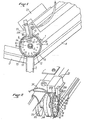
- Figure 1 shows a reading station for movable members 1 each equipped with a hanging rod 2 which are suspended, for example, parts for making clothes.
- each movable member 1 takes a precise position defined in this example by an angle provided between a guide rail 3 slightly descending and a guide rail 4 strongly rising.
- Each movable member 1 has an axis 5 on which a disk 6 is mounted to rotate freely.
- the latter has on one of its main faces a first annular area 7, concentric with the axis 5, preferably located at the periphery to have the largest possible diameter. In this range, radial grooves or grooves 8 are produced.
- the area 9 which directly follows the first area 7 has a succession of through holes 12 whose number and spacings are representative of an identification number.
- the next range 10, closer to the axis 5, has a succession of through holes 13 spaced at a constant pitch in correspondence with a reading rate or a clock rhythm.
- the holes 12 of the area 9 are on the same radial line respectively as a corresponding radial line of a hole 13 of the area 10.
- the area 11, closest to the axis 5, has a single through hole 14 located on the same radial line as a hole 13 in range 10, on which a hole 12 in range 9 may possibly be located.
- Hole 13 in range 10 corresponds to the emission of a signal from start of the read operation during the rotation of the disc 6 around the axis 5.
- a nozzle 15 which is connected by a nozzle 16 to a source of compressed air, and a yoke 17 with two branches 17A, 17B which contain between them each disc 6 located at the reading station.
- the nozzle 15 is oriented to blow air in a direction transverse to the radial ridges 8 and almost tangential to the surface of the disc 6 in order to rotate the latter around the axis 5.
- the adjustment, using a screw, not shown, of the air flow blown through the nozzle 15, makes it possible to obtain a substantially constant speed of rotation of all the disks 5 at a suitable value for reading.
- a branch 17A of the yoke 17 located on one side of the discs 6, carries detectors, arranged radially in the direction of the axis 5, constituted by phototransistors respectively 18, 19, 20, each corresponding to a range 9, 10, 11 holes. These phototransistors are connected to electronic circuits (not shown) known per se, included in a decoding apparatus 21.
- the opposite branch 17B of the yoke 17 located on the other side of the discs 6 carries emitters of infrared radiation (not visible in the drawings), arranged radially in the direction of the axis 5, each in correspondence with the phototransistors 18, 19 , 20. The latter are impressed by the radiation from the transmitters each time a hole in the disc 6 allows the radiation to pass.
- each disk 5 could be provided on tracks 9, 10, 11 with coding and reading of magnetic pads and the detectors of branch 17A could be heads sensitive to the passage of magnetic pads.
- the solution described here is therefore preferable but not compulsory.
- the nozzle 15 could be installed on a branch of a yoke similar to the yoke 17 having a second branch located opposite the other main face of the discs 6.
- This second branch could carry a second compressed air blowing nozzle on radial grooves made on this other main face of the discs.
- Each disc 6 of each movable member 1 is provided in its range 9 with holes 12 whose number and spacings are specific to it and allow it to be identified.
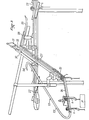
- FIG. 3 shows an example of use of the device of the invention which has just been described.
- Movable members 1 are moved on a general conveyor 22 along which are installed several work stations P.
- Each work station P is associated with a bypass line 23 which successively comprises an input switch blade 24, a path descending guide 25, a portion 26 of the stop workstation P slightly inclined to the horizontal, a lift guide path 27, a guide path 28 down, a shunted g e 29 reintroduction blade on the general conveyor 22.
- the reading station is located at the elbow made by the stop section 26 and the ascent guide path 27.
- the ascent of the movable members is carried out, after reading of identification as explained above, at the using a pneumatic cylinder 30, partially shown, which controls a lifting device 31 included in a sheath 32. This device will not be described in detail because it is not part of the present invention.
- the axis 5 which carries the disc 6 is also the axis of two rollers 33, 34 separated by an interval 35.
- the ascent device comprises a retractable stop during the descent which is placed in the interval 35 to drive the movable member 1 upward during the ascent.
- the jack 30 lowers the ascent device 31 when a movable member 1 is stopped at the reading station.
- the exhaust side of the cylinder 30 during the descent of the ascent device has an air exhaust orifice which is connected by a flexible pipe 36 to the nozzle 16 for connection of the blowing nozzle.
- any other cylinder of an installation whose movement takes place at the time when a reading must be made could be connected by its exhaust orifice to the nozzle or to the blowing nozzles 15.
- the use of a jack intended to evacuate the movable members 1 from the reading station is particularly suitable since this jack comes into operation precisely at the time of an identification reading.
Landscapes
- Engineering & Computer Science (AREA)
- General Physics & Mathematics (AREA)
- Theoretical Computer Science (AREA)
- Computer Networks & Wireless Communication (AREA)
- Transportation (AREA)
- Mechanical Engineering (AREA)
- Physics & Mathematics (AREA)
- Machine Tool Sensing Apparatuses (AREA)
- Feeding Of Articles To Conveyors (AREA)
- Investigating Or Analysing Biological Materials (AREA)
- Discharge Of Articles From Conveyors (AREA)
- General Factory Administration (AREA)
- Control Of Position Or Direction (AREA)
- Transmission And Conversion Of Sensor Element Output (AREA)
- Radio Relay Systems (AREA)
- Magnetic Resonance Imaging Apparatus (AREA)
- Control Of Conveyors (AREA)
- Branching, Merging, And Special Transfer Between Conveyors (AREA)
- Optical Recording Or Reproduction (AREA)
Priority Applications (1)
| Application Number | Priority Date | Filing Date | Title |
|---|---|---|---|
| AT86402134T ATE49310T1 (de) | 1985-10-01 | 1986-09-30 | Kodier- und abtastvorrichtung fuer bewegbare traegerelemente zum fuehren von werkstuecken nach bestimmten werkstellen. |
Applications Claiming Priority (2)
| Application Number | Priority Date | Filing Date | Title |
|---|---|---|---|
| FR8514514 | 1985-10-01 | ||
| FR8514514A FR2588137B1 (fr) | 1985-10-01 | 1985-10-01 | Dispositif de codage et de lecture pour des organes porteurs de pieces a diriger vers des postes de travail determines. |
Publications (2)
| Publication Number | Publication Date |
|---|---|
| EP0220101A1 true EP0220101A1 (de) | 1987-04-29 |
| EP0220101B1 EP0220101B1 (de) | 1990-01-03 |
Family
ID=9323408
Family Applications (1)
| Application Number | Title | Priority Date | Filing Date |
|---|---|---|---|
| EP86402134A Expired - Lifetime EP0220101B1 (de) | 1985-10-01 | 1986-09-30 | Kodier- und Abtastvorrichtung für bewegbare Trägerelemente zum Führen von Werkstücken nach bestimmten Werkstellen |
Country Status (9)
| Country | Link |
|---|---|
| US (1) | US4719449A (de) |
| EP (1) | EP0220101B1 (de) |
| JP (1) | JPS6282323A (de) |
| AT (1) | ATE49310T1 (de) |
| CA (1) | CA1252889A (de) |
| DE (1) | DE3668084D1 (de) |
| ES (1) | ES2002782A6 (de) |
| FR (1) | FR2588137B1 (de) |
| PT (1) | PT83383B (de) |
Cited By (1)
| Publication number | Priority date | Publication date | Assignee | Title |
|---|---|---|---|---|
| IT201700078393A1 (it) * | 2017-07-13 | 2019-01-13 | Gd Spa | Sistema di identificazione di un componente di una macchina confezionatrice. |
Families Citing this family (20)
| Publication number | Priority date | Publication date | Assignee | Title |
|---|---|---|---|---|
| JPH01115520A (ja) * | 1987-10-27 | 1989-05-08 | Fanuc Ltd | ワイヤ自動結線終了検出方式 |
| JPH0361211A (ja) * | 1989-07-27 | 1991-03-18 | Brother Ind Ltd | ハンガーコンベアシステムにおけるハンガー検出装置 |
| US4982189A (en) * | 1989-12-05 | 1991-01-01 | Crown Equipment Corp. | Encoder with wide index |
| JPH03113124U (de) * | 1990-03-06 | 1991-11-19 | ||
| JP2961810B2 (ja) * | 1990-05-17 | 1999-10-12 | ブラザー工業株式会社 | 搬送システムの検出装置 |
| US5571067A (en) * | 1993-11-19 | 1996-11-05 | Ranpak Corp. | Cushioning conversion machine including a length measuring device |
| US6179762B1 (en) | 1994-07-22 | 2001-01-30 | Ranpak Corp. | Cushioning conversion machine |
| US6524230B1 (en) * | 1994-07-22 | 2003-02-25 | Ranpak Corp. | Packing material product and method and apparatus for making, monitoring and controlling the same |
| EP0785862B1 (de) * | 1994-07-22 | 2003-06-11 | Ranpak Corp. | Computergesteuerte polsterumwandlungsmachine |
| US5746005A (en) * | 1996-10-22 | 1998-05-05 | Powerhorse Corporation | Angular position sensor |
| US5829231A (en) * | 1996-11-14 | 1998-11-03 | Ranpak Corporation | Automated cushioning producing and filling system |
| US6170162B1 (en) * | 1999-05-27 | 2001-01-09 | Sarcos, L.C. | Rotary displacement system using differential measuring |
| JP3376546B2 (ja) * | 2000-06-20 | 2003-02-10 | 理英 近藤 | ペン形屈曲線長測器 |
| DE10102278B4 (de) * | 2001-01-18 | 2004-10-28 | Raytheon Marine Gmbh | Datenübertragungsstrecke an einer n.360° Lagerung |
| MXPA05004523A (es) * | 2002-11-01 | 2005-12-12 | Ranpak Corp | Sistema de empacado con medicion de llenado de volumen. |
| EP1528369B1 (de) * | 2003-10-27 | 2014-03-12 | SICK STEGMANN GmbH | Optischer Drehwinkelsensor |
| US7287333B1 (en) * | 2006-05-19 | 2007-10-30 | Her Yuan Chyun Co., Ltd. | Signal detecting device |
| CN102963700B (zh) * | 2012-11-21 | 2015-06-17 | 深圳市华星光电技术有限公司 | 一种机械设备 |
| WO2015159392A1 (ja) * | 2014-04-16 | 2015-10-22 | 三菱電機株式会社 | エレベータの位置検出装置 |
| CN116689316B (zh) * | 2023-08-08 | 2023-10-20 | 江苏安欣医疗科技有限公司 | 一种用于电动腔镜吻合器直管的环绕式检测设备 |
Citations (2)
| Publication number | Priority date | Publication date | Assignee | Title |
|---|---|---|---|---|
| CH512786A (de) * | 1970-03-11 | 1971-09-15 | Hasler Ag | Maschinell ablesbarer magnetischer Informationsträger |
| GB2062917A (en) * | 1979-10-29 | 1981-05-28 | Tanimex Import Export | Code tagging of objects, for example of garments |
Family Cites Families (6)
| Publication number | Priority date | Publication date | Assignee | Title |
|---|---|---|---|---|
| US2934824A (en) * | 1956-05-16 | 1960-05-03 | Philips Corp | Apparatus for measuring angles |
| DE1267003B (de) * | 1963-05-02 | 1968-04-25 | Zuse K G | Einrichtung zur Abtastung digitaler Daten auf Aufzeichnungstraegern |
| US3594735A (en) * | 1968-08-26 | 1971-07-20 | Exact Weight Scale Co The | Data retrieval apparatus |
| SE385988B (sv) * | 1973-06-21 | 1976-07-26 | Platmanufaktur Ab | Identifieringsanordning for formnummerlesning pa maskinformade produkter exv. plast- eller glasprodukter |
| JPS5261063A (en) * | 1975-11-15 | 1977-05-20 | Yamakawa Denshi Kk | Apparatus for reading out information of mobile body |
| JPS5851073B2 (ja) * | 1975-11-25 | 1983-11-14 | アライ ソウイチロウ | カガクセンイニタイスルナツセンチヤクシヨクホウ |
-
1985
- 1985-10-01 FR FR8514514A patent/FR2588137B1/fr not_active Expired
-
1986
- 1986-08-18 US US06/897,265 patent/US4719449A/en not_active Expired - Fee Related
- 1986-09-05 CA CA000517550A patent/CA1252889A/fr not_active Expired
- 1986-09-16 PT PT83383A patent/PT83383B/pt not_active IP Right Cessation
- 1986-09-30 ES ES8602298A patent/ES2002782A6/es not_active Expired
- 1986-09-30 JP JP61230190A patent/JPS6282323A/ja active Pending
- 1986-09-30 EP EP86402134A patent/EP0220101B1/de not_active Expired - Lifetime
- 1986-09-30 DE DE8686402134T patent/DE3668084D1/de not_active Expired - Fee Related
- 1986-09-30 AT AT86402134T patent/ATE49310T1/de not_active IP Right Cessation
Patent Citations (2)
| Publication number | Priority date | Publication date | Assignee | Title |
|---|---|---|---|---|
| CH512786A (de) * | 1970-03-11 | 1971-09-15 | Hasler Ag | Maschinell ablesbarer magnetischer Informationsträger |
| GB2062917A (en) * | 1979-10-29 | 1981-05-28 | Tanimex Import Export | Code tagging of objects, for example of garments |
Non-Patent Citations (1)
| Title |
|---|
| IBM TECHNICAL DISCLOSURE BULLETIN, vol. 8, no. 1, juin 1965, pages 159-160, New York, US; H.J. KISTNER: "Disk-shaped unit record" * |
Cited By (1)
| Publication number | Priority date | Publication date | Assignee | Title |
|---|---|---|---|---|
| IT201700078393A1 (it) * | 2017-07-13 | 2019-01-13 | Gd Spa | Sistema di identificazione di un componente di una macchina confezionatrice. |
Also Published As
| Publication number | Publication date |
|---|---|
| DE3668084D1 (de) | 1990-02-08 |
| PT83383B (pt) | 1992-10-30 |
| CA1252889A (fr) | 1989-04-18 |
| FR2588137B1 (fr) | 1988-01-08 |
| US4719449A (en) | 1988-01-12 |
| JPS6282323A (ja) | 1987-04-15 |
| EP0220101B1 (de) | 1990-01-03 |
| ATE49310T1 (de) | 1990-01-15 |
| ES2002782A6 (es) | 1988-10-01 |
| FR2588137A1 (fr) | 1987-04-03 |
| PT83383A (fr) | 1986-10-01 |
Similar Documents
| Publication | Publication Date | Title |
|---|---|---|
| EP0220101B1 (de) | Kodier- und Abtastvorrichtung für bewegbare Trägerelemente zum Führen von Werkstücken nach bestimmten Werkstellen | |
| US4469217A (en) | Apparatus for transport of capsules and the like | |
| FR2870934A1 (fr) | Appareil de lecture de contour comportant un palpeur mobile en rotation | |
| MY128738A (en) | Wheel speed detecting device for a vehicle | |
| ES2046436T3 (es) | Sistema para separar equidistantemente y trasladar articulos desde un primer hasta un segundo transportadores. | |
| EP0837216A3 (de) | Vorrichtung zum Abwerfen von Kugeln in Bohrlöcher | |
| KR920021203A (ko) | 진공처리장치 | |
| FR2376965A1 (fr) | Dispositif de conservation d'energie cinetique de rotation a volant | |
| EP0395002A3 (de) | Vorrichtung zum Montieren von elektronischen Komponenten | |
| ATE282517T1 (de) | Vorrichtung zur handhabung von vorformling / behältern mittel separat ansteuerbaren armen, die auf einer drehscheibe radial befestigt sind | |
| FR2652161B1 (fr) | Dispositif endoscopique pour la detection de defauts sur metier a tricoter circulaire. | |
| ES2084870T3 (es) | Disposicion para la deteccion sin contacto del numero de revoluciones o posicion de una parte de transmisor giratoria. | |
| US6203458B1 (en) | Speed adjusting device for a drill press | |
| EP0924697A3 (de) | Plattenwiedergabesystem | |
| ES2032893T3 (es) | Revolver para las herramientas de maquinas herramienta. | |
| EP0574422B1 (de) | Verfahren und Vorrichtung zur thermischen Behandlung von Glas- oder Kristallgegenständen in einer senkrecht zu ihrer Rotationsachse stehenden Fläche | |
| FR2743626A1 (fr) | Appareil de lecture de contour, notamment pour verre de lunettes | |
| FR2775910A1 (fr) | Roulette de casino utilisee en jeu d'adresse avec scores automatiques | |
| EP0030196A1 (de) | Vorrichtung zum Erkennen eines Rotationskörpers | |
| FR2752744A1 (fr) | Jeu de production de scores automatise, du type a roulette | |
| EP0261250A1 (de) | Maschine zum Auswählen von Flaschen verschiedener Höhen | |
| WO1996034386A3 (en) | Disc changer with rotatable disc support and disc player including the disc changer | |
| SE9704213L (sv) | Handhavandet av blod i påsar med hjälp av roterande skivor | |
| SU906859A1 (ru) | Дисковый питатель | |
| FI890058A0 (fi) | Gasreningscyklon. |
Legal Events
| Date | Code | Title | Description |
|---|---|---|---|
| PUAI | Public reference made under article 153(3) epc to a published international application that has entered the european phase |
Free format text: ORIGINAL CODE: 0009012 |
|
| 17P | Request for examination filed |
Effective date: 19861002 |
|
| AK | Designated contracting states |
Kind code of ref document: A1 Designated state(s): AT BE CH DE GB IT LI LU NL SE |
|
| 17Q | First examination report despatched |
Effective date: 19890614 |
|
| GRAA | (expected) grant |
Free format text: ORIGINAL CODE: 0009210 |
|
| AK | Designated contracting states |
Kind code of ref document: B1 Designated state(s): AT BE CH DE GB IT LI LU NL SE |
|
| PG25 | Lapsed in a contracting state [announced via postgrant information from national office to epo] |
Ref country code: SE Effective date: 19900103 |
|
| REF | Corresponds to: |
Ref document number: 49310 Country of ref document: AT Date of ref document: 19900115 Kind code of ref document: T |
|
| ITF | It: translation for a ep patent filed | ||
| GBT | Gb: translation of ep patent filed (gb section 77(6)(a)/1977) | ||
| REF | Corresponds to: |
Ref document number: 3668084 Country of ref document: DE Date of ref document: 19900208 |
|
| PGFP | Annual fee paid to national office [announced via postgrant information from national office to epo] |
Ref country code: GB Payment date: 19900921 Year of fee payment: 5 |
|
| PGFP | Annual fee paid to national office [announced via postgrant information from national office to epo] |
Ref country code: AT Payment date: 19900926 Year of fee payment: 5 |
|
| PGFP | Annual fee paid to national office [announced via postgrant information from national office to epo] |
Ref country code: BE Payment date: 19900927 Year of fee payment: 5 |
|
| ITTA | It: last paid annual fee | ||
| PG25 | Lapsed in a contracting state [announced via postgrant information from national office to epo] |
Ref country code: LU Free format text: LAPSE BECAUSE OF NON-PAYMENT OF DUE FEES Effective date: 19900930 |
|
| PGFP | Annual fee paid to national office [announced via postgrant information from national office to epo] |
Ref country code: NL Payment date: 19900930 Year of fee payment: 5 |
|
| PLBE | No opposition filed within time limit |
Free format text: ORIGINAL CODE: 0009261 |
|
| STAA | Information on the status of an ep patent application or granted ep patent |
Free format text: STATUS: NO OPPOSITION FILED WITHIN TIME LIMIT |
|
| PGFP | Annual fee paid to national office [announced via postgrant information from national office to epo] |
Ref country code: CH Payment date: 19901101 Year of fee payment: 5 |
|
| PGFP | Annual fee paid to national office [announced via postgrant information from national office to epo] |
Ref country code: DE Payment date: 19901112 Year of fee payment: 5 |
|
| 26N | No opposition filed | ||
| PG25 | Lapsed in a contracting state [announced via postgrant information from national office to epo] |
Ref country code: LI Effective date: 19910930 Ref country code: GB Effective date: 19910930 Ref country code: CH Effective date: 19910930 Ref country code: BE Effective date: 19910930 Ref country code: AT Effective date: 19910930 |
|
| BERE | Be: lapsed |
Owner name: JICE AUTOMATION Effective date: 19910930 |
|
| PG25 | Lapsed in a contracting state [announced via postgrant information from national office to epo] |
Ref country code: NL Effective date: 19920401 |
|
| NLV4 | Nl: lapsed or anulled due to non-payment of the annual fee | ||
| GBPC | Gb: european patent ceased through non-payment of renewal fee | ||
| REG | Reference to a national code |
Ref country code: CH Ref legal event code: PL |
|
| PG25 | Lapsed in a contracting state [announced via postgrant information from national office to epo] |
Ref country code: DE Effective date: 19920602 |
|
| PGFP | Annual fee paid to national office [announced via postgrant information from national office to epo] |
Ref country code: LU Payment date: 19940630 Year of fee payment: 9 |
|
| EPTA | Lu: last paid annual fee | ||
| PG25 | Lapsed in a contracting state [announced via postgrant information from national office to epo] |
Ref country code: IT Free format text: LAPSE BECAUSE OF NON-PAYMENT OF DUE FEES;WARNING: LAPSES OF ITALIAN PATENTS WITH EFFECTIVE DATE BEFORE 2007 MAY HAVE OCCURRED AT ANY TIME BEFORE 2007. THE CORRECT EFFECTIVE DATE MAY BE DIFFERENT FROM THE ONE RECORDED. Effective date: 20050930 |