EP0219891A1 - Vorrichtung zum Handhaben von Gusspfannen - Google Patents
Vorrichtung zum Handhaben von Gusspfannen Download PDFInfo
- Publication number
- EP0219891A1 EP0219891A1 EP86201544A EP86201544A EP0219891A1 EP 0219891 A1 EP0219891 A1 EP 0219891A1 EP 86201544 A EP86201544 A EP 86201544A EP 86201544 A EP86201544 A EP 86201544A EP 0219891 A1 EP0219891 A1 EP 0219891A1
- Authority
- EP
- European Patent Office
- Prior art keywords
- ladle
- hereinbefore
- station
- casting
- toothed ring
- Prior art date
- Legal status (The legal status is an assumption and is not a legal conclusion. Google has not performed a legal analysis and makes no representation as to the accuracy of the status listed.)
- Granted
Links
Images


Classifications
-
- B—PERFORMING OPERATIONS; TRANSPORTING
- B22—CASTING; POWDER METALLURGY
- B22D—CASTING OF METALS; CASTING OF OTHER SUBSTANCES BY THE SAME PROCESSES OR DEVICES
- B22D37/00—Controlling or regulating the pouring of molten metal from a casting melt-holding vessel
-
- B—PERFORMING OPERATIONS; TRANSPORTING
- B22—CASTING; POWDER METALLURGY
- B22D—CASTING OF METALS; CASTING OF OTHER SUBSTANCES BY THE SAME PROCESSES OR DEVICES
- B22D41/00—Casting melt-holding vessels, e.g. ladles, tundishes, cups or the like
- B22D41/12—Travelling ladles or similar containers; Cars for ladles
- B22D41/13—Ladle turrets
-
- B—PERFORMING OPERATIONS; TRANSPORTING
- B22—CASTING; POWDER METALLURGY
- B22D—CASTING OF METALS; CASTING OF OTHER SUBSTANCES BY THE SAME PROCESSES OR DEVICES
- B22D11/00—Continuous casting of metals, i.e. casting in indefinite lengths
Definitions
- This invention concerns a device to handle ladles serving the casting zone.
- this invention concerns a device suitable to move ladles independently from a tapping position at a furnace, whether the furnace be an electric furnace or of another type, to a casting position after passing through intermediate stations for refining the steel or molten material in general and for cleaning the ladles themselves.
- the device may be applied to zones for continuous casting, zones for casting into ingot moulds or zones for mixed casting with or without zones for emergency casting.
- Ladles are positioned at present below a smelting furnace and then are filled and moved to the casting zone. For such movement a bridge crane is used, or else the ladle is run on appropriate rails and, if necessary, undergoes a series of auxiliary operations before reaching the casting zone or, viceversa, before returning to the furnace.
- GB 677,023 is known and provides for a system to handle a ladle along a substantially circular path served by a bridge crane or hoist. Along this circular path the ladle undergoes a plurality of services, but GB 677,023 does not make exactly clear how the ladle is handled (rotation, tilting, overturning, etc.).
- the system disclosed in GB 677,023 imposes a plurality of restrictions, of which the main ones are as follows: the considerable difficulty of its use in cooperation with continuous casting precisely because of the need to lift the ladle; handling not tied to precise technical timings and therefore not optimum in relation to requirements of the manufacturing cycle; the need to have many ladles available at one and the same time so as to maintain the processing times imposed by the system; the employment of closure means (position 9) which are not suitable for modern casting systems; a very great and therefore uneconomical area is taken up; the systems for handling (tilting, overturning, etc.) the ladle itself are not disclosed in GB 677,023.
- a system according to GB 677,023 can therefore not be installed in view of present requirements regarding time, quality and space relative to modern casting plants but above all to problems of automation which have had to be considered for various years now.
- GB 677,023 is just a description of normal steps performed in a traditional steel mill; the one single new feature is that these steps are carried out along a circular plan.
- FR 1.551.721 is also known but tackles only the problem of continuous casting in a continuous casting plant, that is to say, it tends to overcome the limitation of continuity of casting proper to a ladle because of its defined content. It provides for ladles, charged with molten metal in another part of a steel mill, to be brought to the device and put thereupon in replacement of empty ladles.
- the device of FR 1.551.721 can be applied only to continuous casting plants, and, if necessary, this can be understood from the description of the patent itself.
- the device of FR 1.551.721 does not provide, for example, for rotation of the ladle on its own axis, nor for auxiliary operations at the molten bath, nor does it disclose how operations to restore the ladle can take place since, among other things, such operations are not even provided for.
- FR 1.551.721 does not discloses anything which can be integrated readily and obviously with the disclosures of GB 677,023.
- FR 1.578.603 and FR 1.371.056 conform substantially to F R 1.551.721.
- FR 2.437.258 is substantially the same as FR 1.551.721 but, as compared to the latter, provides for full ladles to be taken independently and empty ladles to be discharged independently.
- DE OS 2.028.078 is also known and discloses one single arm (in contrast to FR 1.551.721 which discloses two independent arms) extending symmetrically in relation to the axis of rotation and also envisages that the ladle can be overturned by a certain angle.
- This invention tends to cover all the steps required of a ladle from the time of the tapping of a furnace to the successive casting operation and also tends to eliminate unnecessary handling, to reduce and regularise the handling times, to standardize the steps of the process and to enable the process to be controlled in an automatic and optimum manner.
- the invention provides for action to be taken only at established positions and at stations for handling and corrective action which are properly equipped in a specialized manner, in times and conditions which are the best for carrying out pre-established operations of use for the smelting bath and for restoring the condition of the ladle.
- the invention enables also the trolleys carrying the ladles and the cranes or bridge cranes of the steel mill which carry the ladles filled with molten steel to be eliminated.
- Such trolleys, cranes or bridge cranes have to bear the weight of a ladle filled with molten metal and therefore of necessity have to possess large dimensions.
- the invention frees the production shed of the bulk and danger involved in the employment of such means to handle ladles full of molten metal, and such handling means are retained only to handle empty ladles.
- the invention provides for the employment of a closed and obligatory circuit carried out by a support means formed of one single body; such support means is specially equipped to be able to carry out all the direct and indirect requirements of the processing cycle.
- auxiliary stations are provided for refining the bath, cleaning the ladles and also for emergency casting.
- the ladles are handled by at least two coaxial handling supports, which are coordinated with each other and each of which engages a ladle.
- two ladles are borne by a device with rotary arms, which constitute the handling supports; the device is located in an intermediate position between the smelting furnace and the casting station.
- smelting furnace are intended to cover the widest possible range, including smelting furnaces, refining furnaces, etc. and therefore any means able to supply molten metal to a ladle.
- the ladles may be alternatively in different positions; for instance, one ladle may be in the charging position whereas the other may be in the casting position, or both of them may be in determined intermediate positions in which they undergo auxiliary operations.
- the aforesaid device with coaxial, independent, rotary arms is suitable to move the ladles from an initial position for charging the molten material to a successive position for refining and/or degassing the molten material, these being processes which also comprise the completion of the chemical composition of the molten material so as to obtain the required alloy, and then also to a successive position for casting either into a continuous casting plant or into ingot moulds or forms or into a plurality of usage means.
- the ladle is positioned thereafter at an appropriate station for cleaning, readying and possibly carrying out minor maintenance work on the ladle, or for replacement of the ladle, while the other ladle is performing the aforesaid charging, refining and casting operations.
- the various steps require, as is known, different lengths of time for their replacement of a ladle, but also enables the cycle to be continuously controlled, downtimes to be avoided and all the operations to be optimized, so that the final result obtained will be a suitable action programmed within the periods of time allowed and with the required features.
- the device is controlled by means which can be programmed to carry out the various steps according , to a preset programme, possibly arranged to suit the characteristics of the plant, the type of casting to be performed and the specific usage means into which the casting is to take place.
- This device is especially suitable in the event of frequent castings, where it is very important that the times should be concentrated, the spaces should be reduced and the quality of the casting should be continuously controlled, with an ability to take continuous and preset corrective action.
- the invention is therefore embodied in a device to handle ladles in cooperation with the casting zone in continuous casting, casting into ingot moulds or forms or mixed casting, such device providing independent, coaxial arms able to rotate by a continuous 360° rotation and to support the ladle, the device being characterized in that such rotary arms handle the ladle also in a tapping station in cooperation with a smelting furnace.
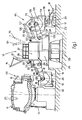
- a device 10 is embodied with two coaxial rotary arms 27, of which one is supported above the other; these arms 27 cooperate with a stationary base 25 and a stationary bearing structure 58.
- the rotary arms 27 can rotate through a continuous rotation of 360° or more and comprise safety and clamping means (not shown here) to obviate even transient positions of reciprocal contact.
- a stand 28 to which in this case it is possible to accede from the interior (Fig.4).
- the arms 27 comprise a carrying structure 62 which can be rotated, by cooperation of a gear wheel 56 with a toothed wheel 57, about a vertical axis of rotation 26.
- the toothed wheel 57 is solidly attached to its respective carrying structure 62.
- the gear wheel 56 is solidly attached to and actuated by a motor reducer unit 55, which is secured to the bearing structure 58.
- Rotation of the arms 27 takes place normally in one direction alone but can be reversed between one station and another, or between several stations, when emergency or corrective action is required.
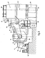
- the work arm 31 is anchored to a support pivot 35 for the support of a ladle 14.
- the support pivot 35 cooperates with a ladle-rotation means 30, which enables the ladle 14 to be rotated by 270° or more.
- the ladle-rotation means 30 anchors the ladle 14 and can position it as required in positions ranging from that with a vertical axis to another position at a required angle.
- a parallelogram-shaped arm 32 together with a connecting body 169 of the ladle-rotation means 30 acts on a control pivot 36 and enables the ladle 14 and ladle-rotation means 30 to be always kept properly positioned.
- the ladle-rotation means 30 (Fig.6) comprises a cradle 69, which supports and positions the ladle 14, being itself fitted so as to be able to oscillate on the support pivot 35.
- An internally toothed ring 70 is also fitted to the support pivot 35 so as to be able to oscillate.
- Such toothed ring 70 covers an angle of less than 360° and is upheld by a carrying body 170 which comprises a support 76 at its end.
- the support 76 comprises a guide 78 cooperating with a clamping bolt 74 able to slot momentarily into a socket on the ladle 14.
- the bolt 74 may be actuated, for instance, by a jack 73.
- the positions of the toothed ring 70 and therefore of the ladle 14 can be monitored by a position monitor, for instance of an encoder type, fitted coaxially to the motor which drives the motor reduction unit 71, for example.
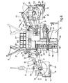
- the ladle can be removed with the system proposed and with suitale lifting equipment by means of a lifting pivot 65, braces 64 and the pivot 66 of the ladle 14 itself.
- braces 64 are supported on a saddle 67, which rests on the cradle 69 through load cells 68 included to weigh the molten metal tapped into the ladle 14.
- Guides 65 may be provided between the cradle 69 and saddle 67 for reciprocal positioning.
- the motor reduction unit 71 sets the toothed ring 70 in rotation and therewith the carrying body 170 and the ladle 14 itself.
- a cover 15 cooperates with the ladle 14 and is supported by a lifting arm 21, which oscillates on a pivot 22 and is actuated by a jack 54.
- the ladle comprises known supporting feet 20, a valve-type closure 19 for the casting of molten material and a jack 59 to actuate the valve 19.
- the ladle 14 comprises a lifting pivot 60 that cooperates with the braces 64 and with the pivot 66 of the ladle to remove or replace the ladle by means of the hook 61 of a crane.
- the ladle 14 can be made to rotate around the vertical axis 26, or around the horizontal axis of the support pivot 35, such latter axis coinciding with the axis of the pivot 66 of the ladle.
- An empty ladle can also be removed or replaced by a crane or hoist at any of the stations.
- the cradle 69 which may comprise the saddle 67 with the load cells 68, is solidly fixed to the toothed ring 70 through the connecting body 169 and carrying body 170.
- toothed ring 70 covers 360° and therefore enables the ladle to be rotated by more than a full revolution.
- the socket 78 of the bolt 74 is comprised directly on the cradle 69.
- stabilisers 77 may be provided between the cradle 69 and saddle 67 and will cooperate with the guides 65.
- the positioning of the ladle 14 may be obtained by hand, or by position monitors located in cooperattion with the support pivot 35, or by the motor of the motor reduction unit 71. Position monitors may also be provided which cooperate also with the rotation pivot 34.
- the stations shown as examples are five in number, four of them being positioned at about 90° from each other about the vertical axis 26, while one is positioned between two of the four (Fig.5).
- Stations in greater number may also be provided and may be positioned at different angles from each other about the vertical axis.
- station 43 for tapping the smelting furnace 11 is located at 180° in relation to a casting station 45 but could also be located at a different angle, and the other stations too could be positioned otherwise than as shown in the figures.
- stations 41 and 42 are shown together but can be separated.
- the stations may also be positioned at about 72° in relation to each other, and the stations 43 and 45 may be positioned at 180° to each other while the stations 46 and 41-42 are positioned at 30° to each other, and so forth.
- the station 43 provides the ladle 14 in a low position with the cover 15 raised, since the ladle is ready to cooperate with a sprue 12 of the smelting furnace 11, which can be brought to a tapping position 111 by a jack 13.
- the station 44 provides for the ladle 14 to be closed by an arched cover 39 and for the bath of molten metal to be heated by a group of heating electrodes 37 which can be raised vertically by a jack 38.
- the station 44 can also perform the degassing of the bath and the possible addition of corrective chemicals.
- the steps of degassing and/or addition of corrective chemicals can be performed at an independent station separate from that where the bath of molten metal is heated.
- the casting station 45 is shown as being applied to continuous casting 24 but can be applied to casting into ingot moulds or forms or to mixed casting.
- the ladle 114 cooperates with a tundish 16 fitted to a trolley 17 which runs on rails 23.
- the trolley 17 may cooperate either with a usage means 24 or with overflow channels 18.
- the ladle 114 is lifted by the work arm 131 above the tundish 16 and is closed with a cover 115.
- the ladle itself is substantially overturned by 180° at least momentarily for the required operations.
- the slag 63 is removed, for example, with the help of a power shovel 40.
- the ladle 114 is replaced, if necessary, in this station, but may also be replaced in any of the other stations.
- the ladle 14 has its axis substantially horizontal but may have its axis vertical in one and/or another of the stations.
- the station 41 provides for the empty ladle 14 to be closed with an appropriate cover 51, which forms part of a heating trolley 50 able to run on guides 52 and supporting a burner 49.
- a heating trolley 50 able to run on guides 52 and supporting a burner 49.
- Such burner serves to heat the ladle so as to prepare it to accommodate the molten metal to be tapped in station 43.
- the station 42 provides for the help of a movable platform 48 to enable the machine operator to have easy access to the closure 47 of the valve 19, to inspect it and, if necessary, to repair it.
Landscapes
- Engineering & Computer Science (AREA)
- Mechanical Engineering (AREA)
- Treatment Of Steel In Its Molten State (AREA)
- Casting Support Devices, Ladles, And Melt Control Thereby (AREA)
Priority Applications (1)
| Application Number | Priority Date | Filing Date | Title |
|---|---|---|---|
| AT86201544T ATE53518T1 (de) | 1985-10-04 | 1986-09-09 | Vorrichtung zum handhaben von gusspfannen. |
Applications Claiming Priority (4)
| Application Number | Priority Date | Filing Date | Title |
|---|---|---|---|
| IT83418/85A IT1187591B (it) | 1985-10-04 | 1985-10-04 | Procedimento per la manipolazione di siviere in asservimento a colata continua e dispositivo effettuante tale procedimento |
| IT8341885 | 1985-10-04 | ||
| IT83397/86A IT1201804B (it) | 1986-08-27 | 1986-08-27 | Dispositivo per la manipolazione di siviere |
| IT8339786 | 1986-08-27 |
Publications (2)
| Publication Number | Publication Date |
|---|---|
| EP0219891A1 true EP0219891A1 (de) | 1987-04-29 |
| EP0219891B1 EP0219891B1 (de) | 1990-06-13 |
Family
ID=26330073
Family Applications (1)
| Application Number | Title | Priority Date | Filing Date |
|---|---|---|---|
| EP86201544A Expired - Lifetime EP0219891B1 (de) | 1985-10-04 | 1986-09-09 | Vorrichtung zum Handhaben von Gusspfannen |
Country Status (10)
| Country | Link |
|---|---|
| US (1) | US4751956A (de) |
| EP (1) | EP0219891B1 (de) |
| KR (1) | KR950012482B1 (de) |
| CN (1) | CN1006124B (de) |
| BR (1) | BR8604831A (de) |
| DE (1) | DE3671850D1 (de) |
| IN (1) | IN165288B (de) |
| MX (1) | MX164606B (de) |
| SU (1) | SU1597093A3 (de) |
| UA (1) | UA5764A1 (de) |
Cited By (3)
| Publication number | Priority date | Publication date | Assignee | Title |
|---|---|---|---|---|
| JPS63115669A (ja) * | 1986-09-25 | 1988-05-20 | ダニエリ・アンド・シー・オフイシネ・メカニク・エスピーエイ | 金属装入材料を半製品に加工する装置及び方法 |
| GB2247203A (en) * | 1990-06-28 | 1992-02-26 | Hitachi Shipbuilding Eng Co | Tundish supply arrangement in a continuous casting apparatus |
| EP0589366A1 (de) * | 1992-09-25 | 1994-03-30 | Marti Technologie Ag | Stahlwerksanordnung |
Families Citing this family (10)
| Publication number | Priority date | Publication date | Assignee | Title |
|---|---|---|---|---|
| FR2609253B1 (fr) * | 1987-01-06 | 1990-04-06 | Clecim Sa | Pivoteur de poches |
| AT391286B (de) * | 1989-02-15 | 1990-09-10 | Voest Alpine Ind Anlagen | Trageinrichtung fuer giesspfannen bei einer stranggiessanlage |
| DE4228432C1 (de) * | 1992-08-27 | 1993-12-16 | Mannesmann Ag | Übergabestation für Gießpfannen |
| JP2007098466A (ja) * | 2005-09-30 | 2007-04-19 | Shinroku Nishiyama | 取鍋を用いた溶湯搬送装置 |
| CN100465292C (zh) * | 2006-12-19 | 2009-03-04 | 江苏沙钢集团有限公司 | 旋转钢包精炼炉 |
| CN104550896A (zh) * | 2014-12-29 | 2015-04-29 | 一重集团大连设计研究院有限公司 | 一种钢包钢渣清理转包台 |
| US10239114B2 (en) | 2016-01-29 | 2019-03-26 | Honda Motor Co., Ltd. | Systems and methods for transporting material |
| CN107685146B (zh) * | 2017-10-09 | 2019-07-05 | 铜陵安东铸钢有限责任公司 | 一种用于大型钢包浇注的转包对准装置 |
| CN114905012B (zh) * | 2022-06-01 | 2024-01-26 | 杭州红山磁性材料有限公司 | 一种铝镍钴磁材的水平连铸方法及装置 |
| CN116174698B (zh) * | 2023-04-25 | 2023-07-04 | 溧阳市双盛机械制造有限公司 | 一种浇铸装置用熔液检测预警设备 |
Citations (5)
| Publication number | Priority date | Publication date | Assignee | Title |
|---|---|---|---|---|
| GB677023A (en) * | 1948-11-22 | 1952-08-06 | Siegfried Junghans | Process and installation for the continuous casting of materials of high melting point, such as steel |
| FR1551721A (de) * | 1967-02-06 | 1968-12-27 | ||
| DE2158902A1 (de) * | 1971-11-27 | 1973-05-30 | Schloemann Ag | Pfannendrehturm an einer stranggiessanlage |
| FR2234946A1 (en) * | 1973-06-26 | 1975-01-24 | Vallourec | Rotary mounting for steel casting ladles - with forked swivel arms for adjusting ladle height in continuous casting |
| FR2361177A1 (fr) * | 1976-08-14 | 1978-03-10 | Demag Ag | Tourelle tournante a poches de coulee pour installations a coulee continue de metaux, notamment d'acier |
Family Cites Families (12)
| Publication number | Priority date | Publication date | Assignee | Title |
|---|---|---|---|---|
| DE285388C (de) * | ||||
| US55442A (en) * | 1866-06-05 | Improvement in casting steel | ||
| FR1371056A (fr) * | 1963-10-09 | 1964-08-28 | Schloemann Ag | Appareil permettant le remplacement des poches de coulée dans les installations de coulée continue |
| DE1758877A1 (de) * | 1967-09-23 | 1971-03-04 | Ural Sawod Tjaselogo Masinostr | Hebe- und Drehtisch fuer Zwischengefaesse in Metallstranggussanlagen |
| DE2028078A1 (de) * | 1970-06-08 | 1971-12-16 | Schloemann AG, 4000 Dusseldorf | Drehturm fur Gießpfannen |
| DE2044768A1 (de) * | 1970-09-10 | 1972-05-25 | ||
| DE2744670C2 (de) * | 1977-10-04 | 1985-06-20 | SMS Schloemann-Siemag AG, 4000 Düsseldorf | Pfannendrehturm |
| FR2437258A1 (fr) * | 1978-09-26 | 1980-04-25 | Clesid Sa | Dispositif de support de poches pour une installation de coulee continue |
| DE2916042B2 (de) * | 1979-04-20 | 1981-07-16 | Mannesmann AG, 4000 Düsseldorf | Drehturm für zwei unabhängig voneinander heb- und senkbare Gießpfannen |
| AT364755B (de) * | 1980-03-05 | 1981-11-10 | Voest Alpine Ag | Tragturm fuer metallurgische gefaesse |
| DE3038876C2 (de) * | 1980-10-15 | 1985-02-21 | Benteler-Werke AG, 4790 Paderborn | Pfannendrehturm |
| US4550058A (en) * | 1983-10-31 | 1985-10-29 | General Electric Company | Soft top coated shaped polycarbonate article |
-
1986
- 1986-09-09 EP EP86201544A patent/EP0219891B1/de not_active Expired - Lifetime
- 1986-09-09 DE DE8686201544T patent/DE3671850D1/de not_active Expired - Fee Related
- 1986-09-16 KR KR1019860007779A patent/KR950012482B1/ko not_active IP Right Cessation
- 1986-09-24 IN IN708/CAL/86A patent/IN165288B/en unknown
- 1986-09-24 MX MX3821A patent/MX164606B/es unknown
- 1986-09-26 US US06/911,814 patent/US4751956A/en not_active Expired - Fee Related
- 1986-09-27 CN CN86106697.9A patent/CN1006124B/zh not_active Expired
- 1986-10-03 SU SU864028299A patent/SU1597093A3/ru active
- 1986-10-03 UA UA4028299A patent/UA5764A1/uk unknown
- 1986-10-03 BR BR8604831A patent/BR8604831A/pt not_active IP Right Cessation
Patent Citations (5)
| Publication number | Priority date | Publication date | Assignee | Title |
|---|---|---|---|---|
| GB677023A (en) * | 1948-11-22 | 1952-08-06 | Siegfried Junghans | Process and installation for the continuous casting of materials of high melting point, such as steel |
| FR1551721A (de) * | 1967-02-06 | 1968-12-27 | ||
| DE2158902A1 (de) * | 1971-11-27 | 1973-05-30 | Schloemann Ag | Pfannendrehturm an einer stranggiessanlage |
| FR2234946A1 (en) * | 1973-06-26 | 1975-01-24 | Vallourec | Rotary mounting for steel casting ladles - with forked swivel arms for adjusting ladle height in continuous casting |
| FR2361177A1 (fr) * | 1976-08-14 | 1978-03-10 | Demag Ag | Tourelle tournante a poches de coulee pour installations a coulee continue de metaux, notamment d'acier |
Cited By (4)
| Publication number | Priority date | Publication date | Assignee | Title |
|---|---|---|---|---|
| JPS63115669A (ja) * | 1986-09-25 | 1988-05-20 | ダニエリ・アンド・シー・オフイシネ・メカニク・エスピーエイ | 金属装入材料を半製品に加工する装置及び方法 |
| GB2247203A (en) * | 1990-06-28 | 1992-02-26 | Hitachi Shipbuilding Eng Co | Tundish supply arrangement in a continuous casting apparatus |
| GB2247203B (en) * | 1990-06-28 | 1994-03-30 | Hitachi Shipbuilding Eng Co | Tundish exchange apparatus for a continuous casting equipment |
| EP0589366A1 (de) * | 1992-09-25 | 1994-03-30 | Marti Technologie Ag | Stahlwerksanordnung |
Also Published As
| Publication number | Publication date |
|---|---|
| DE3671850D1 (de) | 1990-07-19 |
| MX164606B (es) | 1992-09-07 |
| BR8604831A (pt) | 1987-07-07 |
| CN1006124B (zh) | 1989-12-20 |
| KR950012482B1 (ko) | 1995-10-18 |
| KR870003836A (ko) | 1987-05-04 |
| IN165288B (de) | 1989-09-09 |
| SU1597093A3 (ru) | 1990-09-30 |
| EP0219891B1 (de) | 1990-06-13 |
| US4751956A (en) | 1988-06-21 |
| CN86106697A (zh) | 1987-04-22 |
| UA5764A1 (uk) | 1994-12-29 |
Similar Documents
| Publication | Publication Date | Title |
|---|---|---|
| EP0219891A1 (de) | Vorrichtung zum Handhaben von Gusspfannen | |
| US4466104A (en) | Metallurgical plant | |
| US8376196B2 (en) | Apparatus for the interchangeable connection of a casting tube to a spout of a melt vessel | |
| US3693960A (en) | Turret for casting ladles | |
| US4124152A (en) | Truck for transfer tanks in metal plants, particularly for steel strand casting plants | |
| JPS6250058A (ja) | 連続鋳造設備用回転取鍋タレツト | |
| RU2441074C2 (ru) | Металлургический комплекс | |
| FI63532C (fi) | Smaeltbehandlingslaeggning med tippbart behandlingskaerl | |
| CN111215616B (zh) | 一种金属液转运系统 | |
| US4588169A (en) | Arrangement to be used with a tiltable metallurgical vessel | |
| JP2004169082A (ja) | ダクタイル鋳物用溶融鋳鉄の溶製設備及び溶製方法 | |
| JPS62144870A (ja) | とりべ操縦装置 | |
| US4202401A (en) | Apparatus for electroslag casting of heavy ingots | |
| EP2360282B1 (de) | Elektrolichtbogenofen | |
| US4476564A (en) | Gas exhaust nozzle for arc furnaces | |
| US4471487A (en) | Slewing tower for ladles | |
| US4268014A (en) | Transport lift truck for metallurgical vessels, particularly steel mill converters | |
| CN216028041U (zh) | 一种铸造作业辅助装置 | |
| RU2033895C1 (ru) | Установка для заливки металла в литейные формы | |
| JP2013049065A (ja) | 溶鋼流出ゲート開閉装置の着脱台車 | |
| CN114007780A (zh) | 用于在冶金容器的浇口处在更换设备中操作优选铸管的装置 | |
| KR100711491B1 (ko) | 용선래들의 슬래그 배재용 경동장치 | |
| CA1190023A (en) | Carrying tower arrangement for a metallurgical vessel | |
| RU2317177C1 (ru) | Стенд для сталеразливочных ковшей | |
| RU1787667C (ru) | Разливочный стенд машины непрерывного лить заготовок |
Legal Events
| Date | Code | Title | Description |
|---|---|---|---|
| PUAI | Public reference made under article 153(3) epc to a published international application that has entered the european phase |
Free format text: ORIGINAL CODE: 0009012 |
|
| AK | Designated contracting states |
Kind code of ref document: A1 Designated state(s): AT BE CH DE FR GB LI SE |
|
| 17P | Request for examination filed |
Effective date: 19870715 |
|
| 17Q | First examination report despatched |
Effective date: 19880505 |
|
| GRAA | (expected) grant |
Free format text: ORIGINAL CODE: 0009210 |
|
| AK | Designated contracting states |
Kind code of ref document: B1 Designated state(s): AT BE CH DE FR GB LI SE |
|
| REF | Corresponds to: |
Ref document number: 53518 Country of ref document: AT Date of ref document: 19900615 Kind code of ref document: T |
|
| REF | Corresponds to: |
Ref document number: 3671850 Country of ref document: DE Date of ref document: 19900719 |
|
| ET | Fr: translation filed | ||
| PLBI | Opposition filed |
Free format text: ORIGINAL CODE: 0009260 |
|
| 26 | Opposition filed |
Opponent name: CONCAST STANDARD AG Effective date: 19910304 |
|
| PLBN | Opposition rejected |
Free format text: ORIGINAL CODE: 0009273 |
|
| STAA | Information on the status of an ep patent application or granted ep patent |
Free format text: STATUS: OPPOSITION REJECTED |
|
| 27O | Opposition rejected |
Effective date: 19920204 |
|
| EAL | Se: european patent in force in sweden |
Ref document number: 86201544.3 |
|
| PGFP | Annual fee paid to national office [announced via postgrant information from national office to epo] |
Ref country code: FR Payment date: 19950907 Year of fee payment: 10 |
|
| PGFP | Annual fee paid to national office [announced via postgrant information from national office to epo] |
Ref country code: GB Payment date: 19950908 Year of fee payment: 10 |
|
| PGFP | Annual fee paid to national office [announced via postgrant information from national office to epo] |
Ref country code: BE Payment date: 19950914 Year of fee payment: 10 |
|
| PGFP | Annual fee paid to national office [announced via postgrant information from national office to epo] |
Ref country code: SE Payment date: 19950919 Year of fee payment: 10 |
|
| PGFP | Annual fee paid to national office [announced via postgrant information from national office to epo] |
Ref country code: DE Payment date: 19950928 Year of fee payment: 10 |
|
| PGFP | Annual fee paid to national office [announced via postgrant information from national office to epo] |
Ref country code: AT Payment date: 19950930 Year of fee payment: 10 |
|
| PGFP | Annual fee paid to national office [announced via postgrant information from national office to epo] |
Ref country code: CH Payment date: 19951012 Year of fee payment: 10 |
|
| PG25 | Lapsed in a contracting state [announced via postgrant information from national office to epo] |
Ref country code: GB Effective date: 19960909 Ref country code: AT Effective date: 19960909 |
|
| PG25 | Lapsed in a contracting state [announced via postgrant information from national office to epo] |
Ref country code: SE Effective date: 19960910 |
|
| PG25 | Lapsed in a contracting state [announced via postgrant information from national office to epo] |
Ref country code: LI Effective date: 19960930 Ref country code: FR Effective date: 19960930 Ref country code: CH Effective date: 19960930 Ref country code: BE Effective date: 19960930 |
|
| BERE | Be: lapsed |
Owner name: DANIELI & C. OFFICINE MECCANICHE S.P.A. Effective date: 19960930 |
|
| GBPC | Gb: european patent ceased through non-payment of renewal fee |
Effective date: 19960909 |
|
| REG | Reference to a national code |
Ref country code: CH Ref legal event code: PL |
|
| PG25 | Lapsed in a contracting state [announced via postgrant information from national office to epo] |
Ref country code: DE Effective date: 19970603 |
|
| EUG | Se: european patent has lapsed |
Ref document number: 86201544.3 |
|
| REG | Reference to a national code |
Ref country code: FR Ref legal event code: ST |
|
| REG | Reference to a national code |
Ref country code: FR Ref legal event code: ST |