EP0219717B1 - Fixation de sécurité pour la randonnée - Google Patents
Fixation de sécurité pour la randonnée Download PDFInfo
- Publication number
- EP0219717B1 EP0219717B1 EP19860113325 EP86113325A EP0219717B1 EP 0219717 B1 EP0219717 B1 EP 0219717B1 EP 19860113325 EP19860113325 EP 19860113325 EP 86113325 A EP86113325 A EP 86113325A EP 0219717 B1 EP0219717 B1 EP 0219717B1
- Authority
- EP
- European Patent Office
- Prior art keywords
- touring
- hinge member
- step plate
- sliding block
- ski binding
- Prior art date
- Legal status (The legal status is an assumption and is not a legal conclusion. Google has not performed a legal analysis and makes no representation as to the accuracy of the status listed.)
- Expired
Links
Images

Classifications
-
- A—HUMAN NECESSITIES
- A63—SPORTS; GAMES; AMUSEMENTS
- A63C—SKATES; SKIS; ROLLER SKATES; DESIGN OR LAYOUT OF COURTS, RINKS OR THE LIKE
- A63C9/00—Ski bindings
- A63C9/08—Ski bindings yieldable or self-releasing in the event of an accident, i.e. safety bindings
- A63C9/0807—Ski bindings yieldable or self-releasing in the event of an accident, i.e. safety bindings for both towing and downhill skiing
Definitions
- the invention relates to a safety ski binding for touring and downhill skiing according to the preamble of claim 1.
- Such a safety ski binding is described in AT-PS 343 522.
- the flap with two axes is an extension of the touring plate, on which the shoe is held down by a sole holder and a heel holder.
- the flap with the touring plate swivels around the front of the two axes, the axis between the flap and the touring plate allowing the flap to be placed against the front bevel of the shoe sole.
- a disadvantage of this binding is that effortless walking is not easily possible since the roll-off point is given by the front axle, which lies in front of the toe.
- AT-PS 347 304 also shows a binding for touring and downhill skiing, which consists of a base plate which can be clamped between parts of a safety binding attached to the ski.
- a touring plate is hinged to this base plate by means of a pivot axis, on which the shoe can be fastened by means of holding devices.
- This swivel axis is set back to the area of the ball of the foot to give a natural feeling of walking.
- the disadvantage of this binding is the great height caused by the two superimposed plates, which worsens the direct contact between the shoe and the ski.
- a base plate is also used for touring bindings according to AT-PS 357 450.
- the touring plate is hinged to this via a bracket.
- the tab forms a toggle lever with the touring plate, which is locked by the sole of the shoe when the shoe is clamped.
- the skier When changing over to touring, the skier must step out of the binding to unlock the toggle lever; only then can the touring plate be pulled out of its rear catch.
- the knee lever is locked again when the shoe is re-entered into the binding. Apart from the large height of the binding caused by the two plates lying one above the other, the switch from downhill to touring position and vice versa is cumbersome since the shoe has to be removed from the binding.
- the invention has set itself the task of creating a ski binding of the type mentioned, which allows anatomically correct walking with the touring binding.
- the measures according to the invention ensure that when the binding is switched to touring, the touring plate is pulled out of the rear bolt by pivoting the tab, raised and shifted forward and thereby comes to rest on the axis of the tab, which thus forms the point , around which the touring plate can tip, the tipping point comes to lie approximately in the toe to ball area, i.e. is set back from the pivot point normally located in front of the protective tip.
- the position of the tipping point can be adjusted for optimal walking comfort by varying the length of the tab.
- the shape of the tab and the pivot bolt connecting the tab to the touring plate is determined by the features of claims 4 and 5, the design of the tab being such that it serves as a guide for the touring plate in its pivoted state.
- claims 8, 9, 10 and 12 define the design of the slide, the function of which is to lock the pivot pin in the downhill and in the touring position with one of its extensions.
- the slider To release the lock, the slider must be moved towards the ski tip against the force of the tension spring.
- the slider is favorably moved into its recess by using a ski pole without having to bend down or get out of the binding.
- the depth of the clearance between the extensions according to the features of claim 10 is responsible for the maximum tilt angle about the axis, and this should be so large that it is not exceeded during normal touring.
- a distance relationship between the underside of the rear projection of the bearing block and the pivot pin is made, according to which the thickness of the lower extension of the slide is dimensioned.
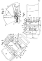
- FIGS. 1 to 5 represents a safety ski binding for touring and downhill skiing.
- a bearing block 2, a support piece 3 and a latch 4 are mounted on the top of a ski 1 by means of screws, not shown.
- the bearing block 2 consists of a base plate 5 screwed to the ski 1 and two side walls 6, the spacing of which is greater than the width of the ski boot tip and which have two projections 6a, 6b in their upper region, the front projection 6a closer to the ski tip
- the upper edge of the side wall 6 extends in the form of a bar approximately to the middle of the bearing block 2 and the rear projection 6b protrudes deep into the bearing block 2.
- the width of the projections 6a, 6b is selected such that it ensures a safe guidance for upper and lower extensions 8, 9 of a slide 7.
- the base plate 5 has in its front part an abutment 5a, which runs perpendicular to the longitudinal direction of the ski and forms a fastening option for one or more tension springs 11.
- a ski boot 18 stands on the touring plate 15 and is held at its front end by a sole holder 17 and at its rear end by a safety heel holder 19. At its rear end, the touring plate 15 is designed so that it can be held down by the ski bar 4. On its underside, the touring plate 15 has a flat 15a in the front area, which enables the touring plate 15 to lie flat on the axis 12 in the touring position, and a recess 15b in the rear area, which receives the ski-fixed support piece 3 in the downward position when the touring plate 15 is locked.
- the slide 7, which is U-shaped in plan view, is fastened to the bearing block 2 by means of a tension spring 11, the tension spring 11 acting on the web 7b of the slide 7.
- a tension spring 11 acting on the web 7b of the slide 7.
- the legs 7a of the slide 7 in the side view consist of two fork-shaped extensions 8, 9, between which there is an exemption 10.
- the upper extension 8, which is further removed from the top of the ski is guided on the front projection 6a of the bearing block wall. Its length is such that it overlaps the pivot pin 14 in the touring position and thus locks it.
- the lower extension 9 of the slider 7 slides with its first section 9a on the base plate 5 of the bearing block 2, the second section 9b points obliquely upwards, while the third section 9c runs parallel to the top of the ski and lies in a downward position in a guide through which Underside of the rear projection 6b of the bearing block wall and the pivot pin section 14a projecting beyond the tab 13 is formed.
- the pivot pin 14 and thus the tab 13 is locked in the downward position.
- the top of the tab 13 and that of the touring plate 15 locked at the rear end lie in one plane.
- the slider 7 is shifted so far in the direction of the ski tip by inserting the tip of the ski pole into the recess 7c of the web 7b that the pivot pin 14 is released and the tab 13 can be pivoted forward about the axis 12. This movement can also be carried out with one foot standing up without getting out of the binding by lifting and moving the touring plate forward.
- the tab 13 is pivoted up to the stop of the touring plate 15 on the axis 12.
- the slide 7 is released, it returns to its starting position as a result of the tension spring 11 and locks the axis 12 of the pivot pin.
- the touring plate 15 Simultaneously with the forward movement of the touring plate 15, it is unlocked at its rear end and comes to rest with its end region on the support piece 3.
- This position of the binding referred to as the touring position, can be seen from FIG. 2.
- the touring plate 15 tilts about the axis 12 up to a maximum tipping angle a, which is determined by the depth of the clearance 10 between the extensions 8, 9 of the slider.
- a maximum tipping angle
- the touring plate 15 can be pivoted about the pivot pin 14 up to pivot angles (3 over 90 ° (see the broken line position in FIG. 3).
- the invention is not limited to the embodiment described and shown in the drawing. Modifications are conceivable without leaving the scope of protection.
- two tabs can also be provided, which grip around the touring plate laterally. In this way, the use of an interlocking toothing of tab and touring plate is unnecessary.
- the two tabs can also end flush with the side walls of the touring plate, the touring plate then being offset on both sides in this area.
- the lower extension of the slide can be supported not only on the section of the pivot pin but also on the axis.
- a compression spring can also be used, which is supported on the one hand on the abutment of the base plate of the bearing block and on the other hand on an inwardly facing extension of the first section of the lower extension of the slide.
Landscapes
- Footwear And Its Accessory, Manufacturing Method And Apparatuses (AREA)
Claims (13)
Applications Claiming Priority (2)
| Application Number | Priority Date | Filing Date | Title |
|---|---|---|---|
| AT283185A AT383748B (de) | 1985-10-01 | 1985-10-01 | Sicherheitsskibindung zum tourengehen |
| AT2831/85 | 1985-10-01 |
Publications (2)
| Publication Number | Publication Date |
|---|---|
| EP0219717A1 EP0219717A1 (fr) | 1987-04-29 |
| EP0219717B1 true EP0219717B1 (fr) | 1989-12-20 |
Family
ID=3540976
Family Applications (1)
| Application Number | Title | Priority Date | Filing Date |
|---|---|---|---|
| EP19860113325 Expired EP0219717B1 (fr) | 1985-10-01 | 1986-09-27 | Fixation de sécurité pour la randonnée |
Country Status (3)
| Country | Link |
|---|---|
| EP (1) | EP0219717B1 (fr) |
| AT (1) | AT383748B (fr) |
| DE (1) | DE3667614D1 (fr) |
Cited By (1)
| Publication number | Priority date | Publication date | Assignee | Title |
|---|---|---|---|---|
| DE102008050044A1 (de) | 2008-10-01 | 2010-04-08 | Marker Deutschland Gmbh | Skibindung |
Families Citing this family (2)
| Publication number | Priority date | Publication date | Assignee | Title |
|---|---|---|---|---|
| AT404799B (de) * | 1997-06-06 | 1999-02-25 | Breuer Martin Dipl Ing | Tourenschibindung mit ballendrehpunkt |
| DE102005056526A1 (de) | 2005-11-25 | 2007-05-31 | Marker Deutschland Gmbh | Skibindung |
Family Cites Families (5)
| Publication number | Priority date | Publication date | Assignee | Title |
|---|---|---|---|---|
| CH166253A (fr) * | 1933-02-25 | 1933-12-31 | Merz Ernest | Dispositif pour la fixation des skis. |
| DE2421602A1 (de) * | 1973-10-20 | 1975-11-13 | Ver Baubeschlag Gretsch Co | Sicherheitsskibindung mit drehbarer stand- oder sohlenplatte |
| AT343522B (de) * | 1975-12-24 | 1978-06-12 | Hausleithner Andreas | Kabellose sicherheitsschibindung |
| CH611523A5 (en) * | 1977-02-23 | 1979-06-15 | Gertsch E & U Ski Produkte | Ski binding which can be optionally changed over for downhill and for cross-country skiing |
| DE3437725C2 (de) * | 1984-02-22 | 1986-04-03 | Heinrich Wunder GmbH & Co KG, 8060 Dachau | Vordere Sohlenhaltevorrichtung |
-
1985
- 1985-10-01 AT AT283185A patent/AT383748B/de not_active IP Right Cessation
-
1986
- 1986-09-27 DE DE8686113325T patent/DE3667614D1/de not_active Expired - Lifetime
- 1986-09-27 EP EP19860113325 patent/EP0219717B1/fr not_active Expired
Cited By (2)
| Publication number | Priority date | Publication date | Assignee | Title |
|---|---|---|---|---|
| DE102008050044A1 (de) | 2008-10-01 | 2010-04-08 | Marker Deutschland Gmbh | Skibindung |
| DE102008050044B4 (de) * | 2008-10-01 | 2017-05-11 | Marker Deutschland Gmbh | Skibindung |
Also Published As
| Publication number | Publication date |
|---|---|
| DE3667614D1 (de) | 1990-01-25 |
| EP0219717A1 (fr) | 1987-04-29 |
| ATA283185A (de) | 1987-01-15 |
| AT383748B (de) | 1987-08-10 |
Similar Documents
| Publication | Publication Date | Title |
|---|---|---|
| DE2533465C2 (de) | Skibremse | |
| EP3566754B1 (fr) | Butée avant de fixation de ski | |
| DE2756897A1 (de) | Sicherheitsskibindung | |
| EP3195906B1 (fr) | Talonniere ayant une configuration de marche | |
| EP0707505B1 (fr) | Dispositif de reglage en longueur | |
| EP0269664B1 (fr) | Frein de ski | |
| EP0120295B1 (fr) | Dispositif de blocage pour le verrouillage réversible d'éléments d'une fixation de ski | |
| AT397920B (de) | Sicherheitsskibindung | |
| EP0247104B1 (fr) | Fixation de ski pour ski de fond ou de tourisme | |
| EP0219717B1 (fr) | Fixation de sécurité pour la randonnée | |
| EP0098515B1 (fr) | Dispositif de réglage en longueur pour fixations de ski | |
| DE3707116A1 (de) | Anordnung zum festhalten eines ski-schuhs auf einem langlauf- oder touren-ski | |
| DE2307427B2 (de) | Skibindung mit einer Sohlenplatte | |
| DE3132636C2 (de) | "Sicherheitsskibindung zum Tourengehen" | |
| EP0394380B1 (fr) | Fixation de securite pour ski | |
| DE3445760A1 (de) | Ausloeseskibindung | |
| EP0272317B1 (fr) | Fixation de securite pour ski | |
| DE2940516A1 (de) | Skibindung | |
| EP1022037A1 (fr) | Fixation Telemark | |
| DE102020203278A1 (de) | Vordereinheit für eine Skibindung mit einer magnetischen Einstiegshilfe | |
| EP0129535A1 (fr) | Ensemble de fixation pour ski de fond avec la chaussure | |
| EP0157091B1 (fr) | Soutien de talon | |
| DE4416531C2 (de) | Snowboardbindung | |
| WO1991015274A1 (fr) | Fixation pour ski de fond ou de randonnee | |
| DE3539315C1 (de) | Tourensicherheitsbindung |
Legal Events
| Date | Code | Title | Description |
|---|---|---|---|
| PUAI | Public reference made under article 153(3) epc to a published international application that has entered the european phase |
Free format text: ORIGINAL CODE: 0009012 |
|
| AK | Designated contracting states |
Kind code of ref document: A1 Designated state(s): CH DE FR LI |
|
| 17P | Request for examination filed |
Effective date: 19870828 |
|
| 17Q | First examination report despatched |
Effective date: 19880824 |
|
| GRAA | (expected) grant |
Free format text: ORIGINAL CODE: 0009210 |
|
| AK | Designated contracting states |
Kind code of ref document: B1 Designated state(s): CH DE FR LI |
|
| REF | Corresponds to: |
Ref document number: 3667614 Country of ref document: DE Date of ref document: 19900125 |
|
| ET | Fr: translation filed | ||
| PLBE | No opposition filed within time limit |
Free format text: ORIGINAL CODE: 0009261 |
|
| STAA | Information on the status of an ep patent application or granted ep patent |
Free format text: STATUS: NO OPPOSITION FILED WITHIN TIME LIMIT |
|
| 26N | No opposition filed | ||
| REG | Reference to a national code |
Ref country code: CH Ref legal event code: PUE Owner name: AMF CORPORATION TRANSFER- HTM SPORTS CORP. Ref country code: CH Ref legal event code: PFA Free format text: TMC CORPORATION, RUESSENSTRASSE 16, WALTERSWIL ZG, BAAR |
|
| REG | Reference to a national code |
Ref country code: FR Ref legal event code: TP Ref country code: FR Ref legal event code: CD |
|
| PGFP | Annual fee paid to national office [announced via postgrant information from national office to epo] |
Ref country code: DE Payment date: 19920627 Year of fee payment: 7 |
|
| PGFP | Annual fee paid to national office [announced via postgrant information from national office to epo] |
Ref country code: FR Payment date: 19920715 Year of fee payment: 7 |
|
| PGFP | Annual fee paid to national office [announced via postgrant information from national office to epo] |
Ref country code: CH Payment date: 19920904 Year of fee payment: 7 |
|
| REG | Reference to a national code |
Ref country code: CH Ref legal event code: PUE Owner name: HTM SPORT- UND FREIZEITGERAETE GMBH |
|
| REG | Reference to a national code |
Ref country code: FR Ref legal event code: TP |
|
| PG25 | Lapsed in a contracting state [announced via postgrant information from national office to epo] |
Ref country code: DE Effective date: 19930211 |
|
| PG25 | Lapsed in a contracting state [announced via postgrant information from national office to epo] |
Ref country code: LI Effective date: 19930930 Ref country code: CH Effective date: 19930930 |
|
| PG25 | Lapsed in a contracting state [announced via postgrant information from national office to epo] |
Ref country code: FR Free format text: LAPSE BECAUSE OF NON-PAYMENT OF DUE FEES Effective date: 19940531 |
|
| REG | Reference to a national code |
Ref country code: CH Ref legal event code: PL |
|
| REG | Reference to a national code |
Ref country code: FR Ref legal event code: ST |