EP0219570B1 - Appareil de commutation - Google Patents
Appareil de commutation Download PDFInfo
- Publication number
- EP0219570B1 EP0219570B1 EP85113511A EP85113511A EP0219570B1 EP 0219570 B1 EP0219570 B1 EP 0219570B1 EP 85113511 A EP85113511 A EP 85113511A EP 85113511 A EP85113511 A EP 85113511A EP 0219570 B1 EP0219570 B1 EP 0219570B1
- Authority
- EP
- European Patent Office
- Prior art keywords
- housing
- switching device
- contact bridge
- blocks
- bridge holder
- Prior art date
- Legal status (The legal status is an assumption and is not a legal conclusion. Google has not performed a legal analysis and makes no representation as to the accuracy of the status listed.)
- Expired - Lifetime
Links
Images

Classifications
-
- H—ELECTRICITY
- H01—ELECTRIC ELEMENTS
- H01H—ELECTRIC SWITCHES; RELAYS; SELECTORS; EMERGENCY PROTECTIVE DEVICES
- H01H1/00—Contacts
- H01H1/58—Electric connections to or between contacts; Terminals
-
- H—ELECTRICITY
- H01—ELECTRIC ELEMENTS
- H01H—ELECTRIC SWITCHES; RELAYS; SELECTORS; EMERGENCY PROTECTIVE DEVICES
- H01H11/00—Apparatus or processes specially adapted for the manufacture of electric switches
- H01H11/0006—Apparatus or processes specially adapted for the manufacture of electric switches for converting electric switches
-
- H—ELECTRICITY
- H01—ELECTRIC ELEMENTS
- H01H—ELECTRIC SWITCHES; RELAYS; SELECTORS; EMERGENCY PROTECTIVE DEVICES
- H01H19/00—Switches operated by an operating part which is rotatable about a longitudinal axis thereof and which is acted upon directly by a solid body external to the switch, e.g. by a hand
- H01H19/54—Switches operated by an operating part which is rotatable about a longitudinal axis thereof and which is acted upon directly by a solid body external to the switch, e.g. by a hand the operating part having at least five or an unspecified number of operative positions
- H01H19/60—Angularly-movable actuating part carrying no contacts
- H01H19/635—Contacts actuated by rectilinearly-movable member linked to operating part, e.g. by pin and slot
- H01H19/6355—Contacts actuated by rectilinearly-movable member linked to operating part, e.g. by pin and slot using axial cam devices for transforming the angular movement into linear movement along the axis of rotation
-
- H—ELECTRICITY
- H01—ELECTRIC ELEMENTS
- H01H—ELECTRIC SWITCHES; RELAYS; SELECTORS; EMERGENCY PROTECTIVE DEVICES
- H01H9/00—Details of switching devices, not covered by groups H01H1/00 - H01H7/00
- H01H9/0066—Auxiliary contact devices
-
- H—ELECTRICITY
- H01—ELECTRIC ELEMENTS
- H01H—ELECTRIC SWITCHES; RELAYS; SELECTORS; EMERGENCY PROTECTIVE DEVICES
- H01H1/00—Contacts
- H01H1/12—Contacts characterised by the manner in which co-operating contacts engage
- H01H1/14—Contacts characterised by the manner in which co-operating contacts engage by abutting
- H01H1/20—Bridging contacts
-
- H—ELECTRICITY
- H01—ELECTRIC ELEMENTS
- H01H—ELECTRIC SWITCHES; RELAYS; SELECTORS; EMERGENCY PROTECTIVE DEVICES
- H01H11/00—Apparatus or processes specially adapted for the manufacture of electric switches
- H01H11/0006—Apparatus or processes specially adapted for the manufacture of electric switches for converting electric switches
- H01H11/0031—Apparatus or processes specially adapted for the manufacture of electric switches for converting electric switches for allowing different types or orientation of connections to contacts
- H01H2011/0037—Apparatus or processes specially adapted for the manufacture of electric switches for converting electric switches for allowing different types or orientation of connections to contacts with removable or replaceable terminal blocks
Definitions
- the invention relates to a switching device with a housing which is essentially rectangular in cross section, with an actuating attachment on the front of the housing which acts on at least one main contact bridge, which is movably guided in the housing between two switching positions, two fixed contact rails for each main contact bridge in the housing are held, which can be connected in the region of two mutually opposite side walls of the housing by means of connecting screws with electrical connecting lines.
- Switchgear of the aforementioned type have to be installed in a variety of ways in practice. You can basically distinguish between two types of installation. In one type of mounting, the actual switching device is fastened behind a mounting plate, the actuating attachment being on the other, the operating side of the mounting plate, and connected to the actual switching device by means of suitable connecting elements through a hole or another opening in the mounting plate.
- This type of assembly of the switchgear is often used for switchboards or control panels if the switchgear is to be quickly accessible.
- a fundamentally different type of assembly of the switchgear is given if they are to be arranged, for example, in rows next to and above one another within, for example, a control cabinet.
- standard mounting rails are often used for mounting the switchgear in rows, which are then attached, for example, to the inner wall of a control cabinet, or the switchgear is mounted directly on a support plate, so that the rear of the switchgear concerned comes to rest on the plate.
- the switchgear must be provided with a number of connection screws for the electrical connection lines. This can be, for example, six connecting screws per switching device or a much larger number.
- a problem can now be seen in the fact that the switchgear must first be firmly installed before the electrical connecting lines are attached and firmly tightened or clamped by the connecting screws.
- the connection screws can practically only be reached and actuated from the back of the switchgear.
- the connection screws can practically only be operated from the front of the switching device using a screwdriver.
- the previously known switchgear was equipped from the outset either for one or for the other type of installation. This has a number of disadvantages, for example a large inventory at the switchgear manufacturer, in order to be able to provide the switchgear suitable for the respective mounting type.
- the invention is based on the object to provide a switching device which can be easily converted to different types of mounting.
- connection screws are accommodated in separate housing blocks, which can be attached in two positions rotated by 180 ° to one another on the side walls, so that the connection screws either from the front or can be actuated from the rear of the housing, and that the fixed contact rails protrude into the housing blocks with their ends protruding from the side walls of the housing.
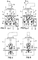
- the switching device has a housing 1 which is essentially rectangular in cross section, with an upper front side 2, a lower rear side 3 and four side walls 4, 5 and 6, 7 in the figure.
- a housing 1 which is essentially rectangular in cross section, with an upper front side 2, a lower rear side 3 and four side walls 4, 5 and 6, 7 in the figure.
- six fixed contact rails 8, 9, 10, 11, 12 and 13 are provided, which can also be seen in particular from FIGS. 2 to 6.
- the ends of these fixed contact rails protrude from the two side walls 4 and 5 of the housing.
- the connecting screws 19, which are used to clamp the electrical connecting lines (not shown) to the fixed contact rails, are accommodated in separate housing blocks 14 and 15.
- the number of connecting screws 19 corresponds to the number of fixed contact rails, so there are a total of six connecting screws in the present case, namely three connecting screws in the housing bracket 14 and a further three in the housing bracket 15.
- each connection screw 19 interacts with a metal cage 23 which is essentially designed as a rectangular frame and can be displaced by the connection screw in question.
- Each housing block has three openings 20, 21 and 22 for the passage of the electrical connecting lines.
- the housing lugs 14 and 15 are drawn at a distance from the housing 1 for the sake of clarity. In the operating position, however, they lie close to the two side walls 4 and 5 of the housing 1, so that the ends of the fixed contact rails 8 to 13 protrude into the housing blocks 14, 15, specifically into the interior of the respective metal cage 23.
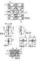
- each housing block 14 and 15 has two main cylindrical projections 24, 25 which can be inserted into the widened areas 31 and 32, respectively, in the upper widened areas 31 when the connecting screws from the front 2, that is in the picture 1 should be operable from above, or after turning the housing block through 180 ° by pushing it into the lower widened areas 32.
- each projection 24, 25 there is an extension 26 and 27 with undercut guide grooves 28 and 29 on both sides provided that, after moving the respective lugs, reaches behind the edges of the narrow area of the respective slot.
- the various positions can also be seen in FIGS. 9 to 13.
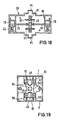
- Auxiliary contact blocks 39 can be attached to the two further side walls 6 and 7 of the housing 1, and also optionally in two positions rotated by 180 °, so that the connecting screws 42 either from the front 2, that is to say in the image of FIG. 1, from above or can be actuated from the rear 3 of the housing.
- the two side walls 6 and 7 of the housing 1, to which the auxiliary contact blocks 39 can be attached each have a vertical slot 36 or a rectangular opening as shown in FIG. 1.
- an auxiliary contact bridge holder 81 is provided in the auxiliary contact block 39, which is equipped with a projection 40. If the auxiliary contact lug 39 is in the selected position on the relevant side wall 6 or 7 and is fastened, for example, by screws, the projection 40 projects through the slot 36 and engages in a form-fitting manner in the recess 38.
- the auxiliary contact bridge holder 81 has two contact bridges 82 and 83, which are arranged on both sides of centrally arranged fixed contact rails 79 and 80 are slidable.
- the auxiliary contact bridges are held in the auxiliary contact bridge holder by means of compression springs.
- the auxiliary contact bridge holder 81 moves to switch on either when viewing FIG. 18 upwards or downwards, so that either the contact bridge 83 or the contact bridge 82 carries out the switch-on process.
- the auxiliary contact bridge holder 81 is guided through ribs (not shown) and through the guide parts 84 and 85.
- the outer ends of the fixed contact rails 79 and 80 are each connected to a metal cage 78 in which the connection screws 42 are seated.
- Openings or openings 43 (FIG. 1) for introducing connecting lines are provided on the adjacent end faces of the auxiliary contact block.
- the auxiliary contact blocks 39 are so wide that the end faces on which the openings 43 are located are flush with the outer surfaces of the housing blocks 14 and 15.
- the connection screws 19 and 42 and the openings or openings 20, 21, 22 and 43 are on both sides of the housing Row to each other. If the auxiliary contact block 39 on the inside, as shown in FIG. 1, is closed by a cover, it goes without saying that a slot 41 corresponding to the slot 36 described must also be provided here, so that the projection 40 can protrude as described.
- FIGS. 3 and 5 in particular illustrate that three main contact bridges 60, 61 and 62 are arranged in a common contact bridge holder 37, specifically under spring pressure in rectangular windows 57, 58 and 59.
- the actuating attachment which in the exemplary embodiment shown has a rotary handle 44, is basically designed in such a way that the contact bridge holder 37 can be moved perpendicular to the front and rear of the housing between the two switching positions, namely the off position according to FIG. 3 and the on position according to FIG.
- the actuating attachment has a rotary handle 44 which, according to the switching positions, can be rotated about an axis 45 running perpendicular to the front side 2 of the housing 1.
- the axis 45 is passed through a latching device 46 and engages in a cylindrical component 52.
- the cylindrical component has two screw turns 53 and 54, which cooperate with parts of the contact bridge holder 37 in a form-fitting manner.
- the screw turns are advantageously designed as grooves, into which projections 63 and 64 of the contact bridge holder 37 engage.
- the distance and the length of the two legs 55 and 56 of the contact bridge holder are selected so that the cylindrical component 52 sits in a switch position, namely in the switch-on position, in the recess between the two legs 55 and 56.
- This switch position is shown in Figure 5.
- the projections 63 and 64 are provided according to FIG. 3 at the ends of the legs 55, 56 and extend radially inwards so that they can engage in the grooves 53, 54.
- the latching device 46 has a central rotating body 47 which is provided with four indentations 90 which are evenly distributed over the circumference.
- two opposing sliders 48 and 49 are arranged, each of which engages in the indentations 90 with a projection 91.
- Each slide 48, 49 is under the pressure of two compression springs 50, 51 provided next to one another.
- the slide is slidably guided between two parallel guides 87 and 88 protruding into the housing 1.
- the cylindrical component 52 and the rotating body 47 of the latching device 46 are expediently formed in one piece and they have a hole with a square cross section with a bevelled edge 89.
- the cross section of the axis 45 of the rotary handle in the region of the hole is adapted accordingly. There are also stops not shown, which only allow turning of the rotary handle 44 between the two switching positions.
- the latching device 46 essentially serves to ensure that the switching operations are carried out quickly and that the contact bridge holder 37 and thus the respective contacts are held securely in the respective switching position.
- FIGS. 2 and 7 also illustrate, a hollow cylinder 65 with a cylindrical bore sits on the axis 45 approximately in the area between the latching device 46 and the turning handle 44. In this area, the axis 45 is cylindrical.
- An essentially U-shaped spring clip 66 cooperates with the hollow cylinder, the legs 67 and 68 of which can engage in two notches 69 of the hollow cylinder 65. This device serves to facilitate assembly.
- the housing block 14 or 15 is provided on an end wall running parallel to the front 2 and rear 3 of the housing 1 with three bores 16, 17 and 18, under which, according to FIG. 14, the connecting screws are rotatably held .
- bars 71 and 72 reach behind the screw heads.
- Each connecting screw can be screwed into a thread of a rectangular metal cage 23, so that the metal cage can be moved in the clamping position to the fixed contact rail 8 to 13 and the connecting line.
- the metal cages 23 are advantageously separated from one another by ribs 70 and guided on these ribs.
- Corresponding ribs 86 can also be provided in the auxiliary contact blocks according to FIG. 18.
- the housing blocks 14 and 15 are advantageously adapted to the width of the housing 1.
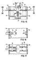
- FIGS. 15 to 17 also show some constituent details, such as the compression spring 73, which holds the main contact bridge 61 in a window of the contact bridge holder 37.
- the form-fitting holder is e.g. the fixed contact rails 9 and 12 shown. From above, these are held in position by ribs 74. In order to avoid a displacement of the main contact rails in the longitudinal direction, they are provided with widenings 75 which are held between further ribs 76 and stops 77. In order to be able to mount the fixed contact rails more easily, it is advantageous to divide the housing 1 approximately at the level of the fixed contact rails, which is indicated by the reference numerals 4a, 4b and 5a, 5b and also by the manner of representation of FIGS. 12 and 13.
Claims (16)
Priority Applications (11)
| Application Number | Priority Date | Filing Date | Title |
|---|---|---|---|
| AT85113511T ATE56306T1 (de) | 1985-10-24 | 1985-10-24 | Schaltgeraet. |
| DE8585113511T DE3579597D1 (de) | 1985-10-24 | 1985-10-24 | Schaltgeraet. |
| EP85113511A EP0219570B1 (fr) | 1985-10-24 | 1985-10-24 | Appareil de commutation |
| AU63630/86A AU593188B2 (en) | 1985-10-24 | 1986-10-06 | Switchgear |
| DK484286A DK166851B1 (da) | 1985-10-24 | 1986-10-10 | Elektrisk omskifter |
| ES8602539A ES2005832A6 (es) | 1985-10-24 | 1986-10-10 | Aparato de conexion |
| US06/918,906 US4713498A (en) | 1985-10-24 | 1986-10-15 | Switch gear |
| MX864111A MX160191A (es) | 1985-10-24 | 1986-10-22 | Aparato de conexion |
| NO864248A NO169464C (no) | 1985-10-24 | 1986-10-23 | Koplingsanordning |
| BR8605185A BR8605185A (pt) | 1985-10-24 | 1986-10-23 | Instrumento de comutacao |
| CA000521411A CA1268849A (fr) | 1985-10-24 | 1986-10-24 | Appareil commutateur |
Applications Claiming Priority (1)
| Application Number | Priority Date | Filing Date | Title |
|---|---|---|---|
| EP85113511A EP0219570B1 (fr) | 1985-10-24 | 1985-10-24 | Appareil de commutation |
Publications (2)
| Publication Number | Publication Date |
|---|---|
| EP0219570A1 EP0219570A1 (fr) | 1987-04-29 |
| EP0219570B1 true EP0219570B1 (fr) | 1990-09-05 |
Family
ID=8193845
Family Applications (1)
| Application Number | Title | Priority Date | Filing Date |
|---|---|---|---|
| EP85113511A Expired - Lifetime EP0219570B1 (fr) | 1985-10-24 | 1985-10-24 | Appareil de commutation |
Country Status (11)
| Country | Link |
|---|---|
| US (1) | US4713498A (fr) |
| EP (1) | EP0219570B1 (fr) |
| AT (1) | ATE56306T1 (fr) |
| AU (1) | AU593188B2 (fr) |
| BR (1) | BR8605185A (fr) |
| CA (1) | CA1268849A (fr) |
| DE (1) | DE3579597D1 (fr) |
| DK (1) | DK166851B1 (fr) |
| ES (1) | ES2005832A6 (fr) |
| MX (1) | MX160191A (fr) |
| NO (1) | NO169464C (fr) |
Cited By (2)
| Publication number | Priority date | Publication date | Assignee | Title |
|---|---|---|---|---|
| DE10061564B4 (de) * | 1999-12-13 | 2007-10-11 | Fuji Electric Co., Ltd., Kawasaki | Anschlußeinheit für mehrpoligen Schalter |
| DE102008017245A1 (de) * | 2008-04-04 | 2009-10-15 | Moeller Gmbh | Steckadapter für ein elektrisches Schaltgerät |
Families Citing this family (39)
| Publication number | Priority date | Publication date | Assignee | Title |
|---|---|---|---|---|
| FR2605150B1 (fr) * | 1986-10-09 | 1988-12-30 | Telemecanique Electrique | Appareil electro-magnetique de commutation ayant des interrupteurs interchangeables |
| US4901046A (en) * | 1987-06-09 | 1990-02-13 | Hubert Laurenz Naimer | Manually actuated on-off switch with electromagnetic release |
| US5165533A (en) * | 1988-04-18 | 1992-11-24 | Consolidated Resource Corp. Of America, Inc. | Screw controlled contact mechanism |
| US5003430A (en) * | 1988-09-16 | 1991-03-26 | Watlow/Winona, Inc. | Controller with snap-on relay module |
| DE4003745A1 (de) * | 1990-02-08 | 1991-08-14 | Ego Elektro Blanc & Fischer | Schaltgeraet |
| FR2658659B1 (fr) * | 1990-02-16 | 1996-07-19 | Alsthom Gec | Contacteur a courant continu pour puissances elevees. |
| FR2685557B1 (fr) * | 1991-12-23 | 1995-06-23 | Baco Const Elect | Appareil electrique avec bornes de raccordement. |
| DE4234619C2 (de) * | 1992-10-14 | 1994-09-22 | Kloeckner Moeller Gmbh | Mit Schützen zu kombinierendes Überlastrelais |
| DK171005B1 (da) * | 1993-03-26 | 1996-04-15 | Lk As | Grundmodel til en flerpolet elektrisk motorafbryder og motorafbryder med sådanne grundmoduler |
| FI93502C (fi) * | 1993-08-13 | 1995-04-10 | Abb Stroemberg Kojeet Oy | Kytkinlaite |
| JP2923736B2 (ja) * | 1994-08-18 | 1999-07-26 | 春日電機株式会社 | 多段階操作インタ−ロック付押釦開閉器 |
| NL9401386A (nl) * | 1994-08-26 | 1996-04-01 | Holec Syst & Componenten | Draaischakelaar met vergrendelbare schakelstandblokkering. |
| US5532441A (en) * | 1994-10-13 | 1996-07-02 | Square D Company | Contact block having convertible normally open or normally closed electrical contact |
| FI953115A0 (fi) * | 1995-06-21 | 1995-06-21 | Abb Stroemberg Kojeet Oy | Kopplingsanordning |
| NL1000906C2 (nl) * | 1995-07-31 | 1997-02-04 | Holec Syst & Componenten | Schakelsysteem met aansluitmodules. |
| DE19707563C2 (de) * | 1997-02-26 | 1999-02-11 | Schneider Electric Gmbh | Schaltvorrichtung |
| US6034584A (en) * | 1997-08-06 | 2000-03-07 | Allen-Bradley Company, Llc | Arrangement for mechanically coupling an overload relay to a contactor |
| DE19812503C1 (de) * | 1998-03-21 | 1999-12-09 | Moeller Gmbh | Drehbetätigter Schutzschalter mit voreilendem Hilfsschalter |
| DE19814400C1 (de) * | 1998-03-31 | 1999-12-23 | Moeller Gmbh | Elektromagnetisches Schaltgerät mit mehrteiligem Gehäuse |
| FR2778789B1 (fr) * | 1998-05-14 | 2000-06-30 | Socomec Sa | Appareil de coupure electrique pour installation electrique a basse tension alternative |
| DE29916001U1 (de) * | 1999-09-13 | 2000-01-05 | Abb Patent Gmbh | Installationsschalter |
| DE19949565C1 (de) * | 1999-10-14 | 2001-05-10 | Bartec Componenten & Syst Gmbh | Schalteinrichtung |
| DE10210228A1 (de) * | 2002-01-10 | 2003-07-31 | Peterreins Schalttechnik Gmbh | Mehrphasiger Schalter |
| US6743995B2 (en) | 2002-06-06 | 2004-06-01 | Judco Manufacturing, Inc. | Quiet pushbutton switch |
| US7498538B1 (en) | 2007-07-20 | 2009-03-03 | Judco Manufacturing, Inc. | Sliding contact switch |
| US7880107B1 (en) | 2007-10-12 | 2011-02-01 | Judco Manufacturing, Inc. | Momentary push button switch |
| DE102008062548B3 (de) * | 2008-12-16 | 2010-01-07 | Siemens Aktiengesellschaft | Schaltvorrichtung zum mittelbaren Schließen oder Trennen einer Schaltstelle |
| US8579641B1 (en) | 2011-03-14 | 2013-11-12 | Google Inc. | Multi-orientation plug |
| US8398430B1 (en) | 2011-03-14 | 2013-03-19 | Google Inc. | Multi-orientation plug |
| ES2402529B1 (es) * | 2011-10-27 | 2014-10-15 | Gave Electro, S.L. | Conmutador de levas |
| USD738323S1 (en) | 2012-07-16 | 2015-09-08 | Abb Oy | Cam switch |
| US8777676B1 (en) * | 2012-12-21 | 2014-07-15 | Hubbell Incorporated | Universal mount contact block with reversible protected wiring terminals |
| ITTO20130457A1 (it) * | 2013-06-04 | 2014-12-05 | Menber S Spa | Interruttore, in particolare interruttore staccabatterie per veicoli e simili |
| USD738318S1 (en) * | 2013-08-20 | 2015-09-08 | Siemens Aktiengesellschaft | Switch |
| EP3188322B1 (fr) | 2015-12-29 | 2018-01-31 | Axis AB | Borne de mise à la terre pour un dispositif électronique |
| DE102018219224A1 (de) * | 2018-11-12 | 2020-05-14 | Eaton Intelligent Power Limited | Schalter |
| GB2589107A (en) * | 2019-09-05 | 2021-05-26 | Eaton Intelligent Power Ltd | Semi-independent switch-disconnector |
| EP4099354A1 (fr) * | 2021-06-01 | 2022-12-07 | ABB Schweiz AG | Commutateur électrique |
| WO2023284999A1 (fr) * | 2021-07-12 | 2023-01-19 | Eaton Intelligent Power Limited | Interrupteur pour déconnecter un circuit électrique |
Family Cites Families (15)
| Publication number | Priority date | Publication date | Assignee | Title |
|---|---|---|---|---|
| US2422097A (en) * | 1945-05-19 | 1947-06-10 | Cutler Hammer Inc | Electric switch |
| US2761041A (en) * | 1953-06-24 | 1956-08-28 | Ite Circuit Breaker Ltd | Auxiliary and latched contact switches |
| DE1006038B (de) * | 1955-09-24 | 1957-04-11 | Siemens Ag | Sockel fuer ein elektrisches Geraet zur Befestigung des Geraetes an einer Montageunterlage |
| US2918554A (en) * | 1957-09-30 | 1959-12-22 | Murray Mfg Corp | Interlock contact mechanism |
| US2947827A (en) * | 1957-11-29 | 1960-08-02 | Clark Controller Co | Cam-operable twin-switches |
| DE1257932B (de) * | 1958-05-31 | 1968-01-04 | Siemens Ag | Druckknopftastschalter |
| US3201533A (en) * | 1961-06-28 | 1965-08-17 | Ite Circuit Breaker Ltd | Rotary type control switch |
| US3296567A (en) * | 1964-05-25 | 1967-01-03 | Westinghouse Electric Corp | Electric control device |
| DE1640849B1 (de) * | 1966-08-02 | 1970-09-24 | Licentia Gmbh | Druckknopftastschalter |
| GB1225963A (fr) * | 1967-02-27 | 1971-03-24 | ||
| US3679854A (en) * | 1971-06-18 | 1972-07-25 | Square D Co | Rotatably reversible connector for electric circuit breaker |
| US4066323A (en) * | 1975-01-20 | 1978-01-03 | Norden Alexander | Electrical terminal blocks |
| US3995932A (en) * | 1975-06-20 | 1976-12-07 | Allen-Bradley Company | Terminal for convertible contact module |
| DE7913111U1 (de) * | 1979-05-07 | 1982-09-09 | Starkstrom Gummersbach GmbH, 5277 Marienheide | Elektrisches Schaltgerät, insbesondere Nockenschalter |
| DE8023868U1 (de) * | 1980-09-06 | 1982-03-25 | Starkstrom Gummersbach GmbH, 5277 Marienheide | Kontaktvorrichtung für Niederspannungs-Schaltgeräte, insbesondere Schütze |
-
1985
- 1985-10-24 EP EP85113511A patent/EP0219570B1/fr not_active Expired - Lifetime
- 1985-10-24 DE DE8585113511T patent/DE3579597D1/de not_active Expired - Lifetime
- 1985-10-24 AT AT85113511T patent/ATE56306T1/de not_active IP Right Cessation
-
1986
- 1986-10-06 AU AU63630/86A patent/AU593188B2/en not_active Ceased
- 1986-10-10 ES ES8602539A patent/ES2005832A6/es not_active Expired
- 1986-10-10 DK DK484286A patent/DK166851B1/da not_active IP Right Cessation
- 1986-10-15 US US06/918,906 patent/US4713498A/en not_active Expired - Lifetime
- 1986-10-22 MX MX864111A patent/MX160191A/es unknown
- 1986-10-23 BR BR8605185A patent/BR8605185A/pt not_active IP Right Cessation
- 1986-10-23 NO NO864248A patent/NO169464C/no not_active IP Right Cessation
- 1986-10-24 CA CA000521411A patent/CA1268849A/fr not_active Expired - Fee Related
Cited By (3)
| Publication number | Priority date | Publication date | Assignee | Title |
|---|---|---|---|---|
| DE10061564B4 (de) * | 1999-12-13 | 2007-10-11 | Fuji Electric Co., Ltd., Kawasaki | Anschlußeinheit für mehrpoligen Schalter |
| DE102008017245A1 (de) * | 2008-04-04 | 2009-10-15 | Moeller Gmbh | Steckadapter für ein elektrisches Schaltgerät |
| DE102008017245B4 (de) * | 2008-04-04 | 2010-03-25 | Moeller Gmbh | Steckadapter für ein elektrisches Schaltgerät |
Also Published As
| Publication number | Publication date |
|---|---|
| DK484286D0 (da) | 1986-10-10 |
| NO864248D0 (no) | 1986-10-23 |
| US4713498A (en) | 1987-12-15 |
| DE3579597D1 (de) | 1990-10-11 |
| AU6363086A (en) | 1987-04-30 |
| EP0219570A1 (fr) | 1987-04-29 |
| DK484286A (da) | 1987-04-25 |
| CA1268849A (fr) | 1990-05-08 |
| NO169464B (no) | 1992-03-16 |
| DK166851B1 (da) | 1993-07-19 |
| ATE56306T1 (de) | 1990-09-15 |
| ES2005832A6 (es) | 1989-04-01 |
| BR8605185A (pt) | 1987-07-28 |
| NO169464C (no) | 1992-06-24 |
| MX160191A (es) | 1989-12-21 |
| AU593188B2 (en) | 1990-02-01 |
| NO864248L (no) | 1987-04-27 |
Similar Documents
| Publication | Publication Date | Title |
|---|---|---|
| EP0219570B1 (fr) | Appareil de commutation | |
| EP0264840A2 (fr) | Méthode et dispositif pour monter des composants électriques sur une plaque à circuit imprimé | |
| EP0727797B1 (fr) | Interrupteur de sécurité | |
| AT517769B1 (de) | Energiezähler-Anschlussklemmenblock mit Überbrückungsvorrichtung | |
| EP0190373B1 (fr) | Dispositif de fixation rapide pour interrupteurs de protection | |
| EP0019141A1 (fr) | Interrupteur à cames | |
| EP0017124A1 (fr) | Appareil électrique, notamment appareil d'installation | |
| DE4013371C1 (en) | Transverse rail fixer for frame shanks in electrical equipment cabinet - uses fitting plate and joint block with aligned threaded bores | |
| DE2355509C2 (de) | Montageeinheit für Elektro-Installationszwecke | |
| EP1193822B1 (fr) | Support de barres bus | |
| DE2448111B2 (de) | Anordnung zum anschluss elektrischer leitungen an ein elektrisches geraet | |
| DE4446166C1 (de) | Vorrichtung zum Befestigen eines elektrischen Gerätes an einer Montageplatte | |
| CH615292A5 (fr) | ||
| DE19647781C2 (de) | Montageeinheit mit einer Montageschiene | |
| DE102019118816B4 (de) | Kontaktträger zum Bereitstellen einer Kontaktierung für eine Verkabelung in einem Fahrzeug | |
| DE2713425A1 (de) | Kombination zweier schuetze | |
| EP0989760B1 (fr) | Bloc de connection pour la technique de télécommunications | |
| DE2905317A1 (de) | Schalttafelgeraet mit einem befestigungselement | |
| WO2014032852A1 (fr) | Dispositif de commande et de signalisation destiné à être monté dans une ouverture de montage d'une plaque de montage | |
| DE19530844A1 (de) | Elektrischer Stecker mit einem Betätigungsschieber | |
| DE3027365A1 (de) | Messinstrumentengehaeuse | |
| DE3242211C2 (fr) | ||
| DE19715220A1 (de) | Vorrichtung zur Aufnahme von Schaltgeräten oder dergleichen, insbesondere Sammelschienenadapter | |
| DE1487450C (de) | Drucktaste fur Fernmelde , insbeson dere Fernsprechgerate | |
| EP3805692A1 (fr) | Système de maintien et de fixation modulaire pour une technique de la mesure |
Legal Events
| Date | Code | Title | Description |
|---|---|---|---|
| PUAI | Public reference made under article 153(3) epc to a published international application that has entered the european phase |
Free format text: ORIGINAL CODE: 0009012 |
|
| AK | Designated contracting states |
Kind code of ref document: A1 Designated state(s): AT BE CH DE FR GB IT LI LU NL SE |
|
| 17P | Request for examination filed |
Effective date: 19871020 |
|
| 17Q | First examination report despatched |
Effective date: 19891228 |
|
| GRAA | (expected) grant |
Free format text: ORIGINAL CODE: 0009210 |
|
| RAP1 | Party data changed (applicant data changed or rights of an application transferred) |
Owner name: SQUARE D COMPANY (DEUTSCHLAND) GMBH |
|
| AK | Designated contracting states |
Kind code of ref document: B1 Designated state(s): AT BE CH DE FR GB IT LI LU NL SE |
|
| REF | Corresponds to: |
Ref document number: 56306 Country of ref document: AT Date of ref document: 19900915 Kind code of ref document: T |
|
| GBT | Gb: translation of ep patent filed (gb section 77(6)(a)/1977) | ||
| REF | Corresponds to: |
Ref document number: 3579597 Country of ref document: DE Date of ref document: 19901011 |
|
| ET | Fr: translation filed | ||
| ITF | It: translation for a ep patent filed |
Owner name: STUDIO JAUMANN |
|
| PLBE | No opposition filed within time limit |
Free format text: ORIGINAL CODE: 0009261 |
|
| STAA | Information on the status of an ep patent application or granted ep patent |
Free format text: STATUS: NO OPPOSITION FILED WITHIN TIME LIMIT |
|
| 26N | No opposition filed | ||
| ITTA | It: last paid annual fee | ||
| EPTA | Lu: last paid annual fee | ||
| EAL | Se: european patent in force in sweden |
Ref document number: 85113511.1 |
|
| PGFP | Annual fee paid to national office [announced via postgrant information from national office to epo] |
Ref country code: NL Payment date: 19990921 Year of fee payment: 15 |
|
| PGFP | Annual fee paid to national office [announced via postgrant information from national office to epo] |
Ref country code: LU Payment date: 19991022 Year of fee payment: 15 |
|
| PGFP | Annual fee paid to national office [announced via postgrant information from national office to epo] |
Ref country code: BE Payment date: 19991117 Year of fee payment: 15 |
|
| PG25 | Lapsed in a contracting state [announced via postgrant information from national office to epo] |
Ref country code: LU Free format text: LAPSE BECAUSE OF NON-PAYMENT OF DUE FEES Effective date: 20001024 |
|
| PG25 | Lapsed in a contracting state [announced via postgrant information from national office to epo] |
Ref country code: BE Free format text: LAPSE BECAUSE OF NON-PAYMENT OF DUE FEES Effective date: 20001031 |
|
| BERE | Be: lapsed |
Owner name: SQUARE D CY (DEUTSCHLAND) G.M.B.H. Effective date: 20001031 |
|
| PG25 | Lapsed in a contracting state [announced via postgrant information from national office to epo] |
Ref country code: NL Free format text: LAPSE BECAUSE OF NON-PAYMENT OF DUE FEES Effective date: 20010501 |
|
| NLV4 | Nl: lapsed or anulled due to non-payment of the annual fee |
Effective date: 20010501 |
|
| REG | Reference to a national code |
Ref country code: GB Ref legal event code: IF02 |
|
| PGFP | Annual fee paid to national office [announced via postgrant information from national office to epo] |
Ref country code: FR Payment date: 20030930 Year of fee payment: 19 |
|
| PGFP | Annual fee paid to national office [announced via postgrant information from national office to epo] |
Ref country code: DE Payment date: 20031004 Year of fee payment: 19 |
|
| PGFP | Annual fee paid to national office [announced via postgrant information from national office to epo] |
Ref country code: AT Payment date: 20040916 Year of fee payment: 20 |
|
| PGFP | Annual fee paid to national office [announced via postgrant information from national office to epo] |
Ref country code: SE Payment date: 20040920 Year of fee payment: 20 |
|
| PGFP | Annual fee paid to national office [announced via postgrant information from national office to epo] |
Ref country code: GB Payment date: 20041011 Year of fee payment: 20 |
|
| PGFP | Annual fee paid to national office [announced via postgrant information from national office to epo] |
Ref country code: CH Payment date: 20041013 Year of fee payment: 20 |
|
| PG25 | Lapsed in a contracting state [announced via postgrant information from national office to epo] |
Ref country code: DE Free format text: LAPSE BECAUSE OF NON-PAYMENT OF DUE FEES Effective date: 20050503 |
|
| PG25 | Lapsed in a contracting state [announced via postgrant information from national office to epo] |
Ref country code: FR Free format text: LAPSE BECAUSE OF NON-PAYMENT OF DUE FEES Effective date: 20050630 |
|
| REG | Reference to a national code |
Ref country code: FR Ref legal event code: ST |
|
| PG25 | Lapsed in a contracting state [announced via postgrant information from national office to epo] |
Ref country code: GB Free format text: LAPSE BECAUSE OF EXPIRATION OF PROTECTION Effective date: 20051023 |
|
| REG | Reference to a national code |
Ref country code: GB Ref legal event code: PE20 |
|
| EUG | Se: european patent has lapsed | ||
| REG | Reference to a national code |
Ref country code: CH Ref legal event code: PL |