EP0217738A1 - Drain valve device for a sanitary installation - Google Patents
Drain valve device for a sanitary installation Download PDFInfo
- Publication number
- EP0217738A1 EP0217738A1 EP19860810100 EP86810100A EP0217738A1 EP 0217738 A1 EP0217738 A1 EP 0217738A1 EP 19860810100 EP19860810100 EP 19860810100 EP 86810100 A EP86810100 A EP 86810100A EP 0217738 A1 EP0217738 A1 EP 0217738A1
- Authority
- EP
- European Patent Office
- Prior art keywords
- valve
- fixed member
- radial element
- evacuation device
- open position
- Prior art date
- Legal status (The legal status is an assumption and is not a legal conclusion. Google has not performed a legal analysis and makes no representation as to the accuracy of the status listed.)
- Withdrawn
Links
Images

Classifications
-
- E—FIXED CONSTRUCTIONS
- E03—WATER SUPPLY; SEWERAGE
- E03C—DOMESTIC PLUMBING INSTALLATIONS FOR FRESH WATER OR WASTE WATER; SINKS
- E03C1/00—Domestic plumbing installations for fresh water or waste water; Sinks
- E03C1/12—Plumbing installations for waste water; Basins or fountains connected thereto; Sinks
- E03C1/22—Outlet devices mounted in basins, baths, or sinks
- E03C1/23—Outlet devices mounted in basins, baths, or sinks with mechanical closure mechanisms
- E03C1/2306—Outlet devices mounted in basins, baths, or sinks with mechanical closure mechanisms the plug being operated by hand contact
-
- E—FIXED CONSTRUCTIONS
- E03—WATER SUPPLY; SEWERAGE
- E03C—DOMESTIC PLUMBING INSTALLATIONS FOR FRESH WATER OR WASTE WATER; SINKS
- E03C1/00—Domestic plumbing installations for fresh water or waste water; Sinks
- E03C1/12—Plumbing installations for waste water; Basins or fountains connected thereto; Sinks
- E03C1/22—Outlet devices mounted in basins, baths, or sinks
- E03C1/23—Outlet devices mounted in basins, baths, or sinks with mechanical closure mechanisms
Definitions
- valve discharge devices used in sanitary appliances such as baths, sinks and bidets.
- the simplest consists of a stopper which is placed by hand and which is connected to the container by a chain.
- This system is not hygienic, bacteria can attach to the chain; moreover, it is unsightly in the open position; an involuntary pull on the chain causes the unexpected flow.
- valve devices are actuated by a linkage connected to a control placed either on the sanitary appliance, close to the valve or combined with it, or even laterally next to the container. They have the drawback of complex and costly manufacturing and of difficult assembly. In addition, they tend to out of balance with use and therefore require maintenance. We have also thought of using the principle of the screw or that of helical cams whose applications are common in mechanics, for example to obtain the back and forth of a part by its support on helical bearings in rotation and vice versa.
- the present invention overcomes the above drawbacks by providing a direct control device, of a simple construction and in accordance with claim 1, and where the instantaneous extraction of the valve leaves the plug free of any obstacle.
- the plug 22 is threaded and fixed to the sanitary appliance 20 by means of a tightening nut 23 compressing a seal 24 against the part 20 of this appliance.
- the interior of the lower part of the plug 22 constitutes a fixed member, of generally annular cylindrical shape, the upper surface of which forms three identical cams 25 which can also be seen in the form developed in FIG. 7.
- Each cam 25, of which the guide surface is inclined (for example at 45 °) relative to the axis and in the direction of flow, therefore towards the inside of the bung 22, in order to avoid any retention of solid material, has a lower part 26, a cam track 27, and an upper part 28.
- the slope of this upper part 28 seen from the front is zero, or even slightly reversed.
- Three stops 29 acting on two of their faces are arranged between the cams 25 ( Figure 2).
- the upper surface of the stops 29 is inclined inwards in the same way as the cam surfaces 26, 27, 28.
- the valve 30 rests on a fixed seat 31.
- the contact is ensured by an annular seal 32.
- the vertical rod 33 of the valve is formed by the junction of three radial elements 34 of which at least part 35 is formed of a self-lubricating material and resistant to wear and the oblique lower part of which slides on the cams described above. In the position represented by FIG. 1, contact is not established between the cams 25 and the radial elements 34 and it is the head 30 of the valve which rests on its seat 31.
- the three radial elements 34 guarantee, by sliding with play in the threaded plug 22, the vertical retention of the valve in any position, while promoting the flow of water.
- the degree of opening of the valve is preset by the level of the surface 28 and by the length of the radial elements 34, so as to prevent the passage of objects such as rings, toothpaste plugs or the like.
- the angular position of the rib 36 indicates whether the valve is closed or open.
- the cams 25 are replaced by bearing surfaces 45 and stops 46 corresponding to the stops 29.
- the bearing surfaces 45 are at constant level but inclined inwards, like the cam surfaces 26, 27 , 28 of the first embodiment.
- the upper surface of the stops 46 is inclined in the same way.
- Each bearing surface 45 ends at one end with a stop 46 and at its opposite end with an interruption 52.
- the valve 47 has a rod forming three radial elements 48, a seal 49 cooperating with a seat 50, and a gripping and actuating rib 51.
- the elements 48 have parts 53 similar to the parts 35, designed to cooperate with conical bearing surfaces 45 d ' a piece 44 similar to 25.
- this second embodiment is as follows. In the position of the organs according to fig. 8, 9 and 10, the elements 48 are in the interruptions or voids 52 and the valve rests closed on its seat 50. If the rib 51 is grasped, lift the valve 47 to release the elements 48 from the voids 52 and that it is rotated in the direction of the arrows in fig. 10, these elements are brought to abut against the stops 46. Then the rib 51 is released, the parts 53 come to rest on the bearing surfaces 45 (if they had been raised above). Therefore, the valve is and remains open. We are then in the position illustrated by FIGS. 11 to 13. To close the valve, simply rotate it in the direction of the arrows in fig. 13, until the elements 48 arrive against the stops 46 and fall into the interruptions or voids 52 and we find our in the position according to FIG. 8 to 10. Thus the opening and closing are done without trial and error.
Landscapes
- Engineering & Computer Science (AREA)
- Mechanical Engineering (AREA)
- Environmental & Geological Engineering (AREA)
- Health & Medical Sciences (AREA)
- Life Sciences & Earth Sciences (AREA)
- Hydrology & Water Resources (AREA)
- Public Health (AREA)
- Water Supply & Treatment (AREA)
- Mechanically-Actuated Valves (AREA)
- Sink And Installation For Waste Water (AREA)
Abstract
Description
On connaît différents dispositifs d'évacuation à clapet utilisés dans les appareils sanitaires tels que baignoires, lavabos et bidets. Le plus simple consiste en un bouchon que l'on place à la main et qui est relié au récipient par une chaînette. Ce systéme n'est pas hygiénique, des bactéries pouvant se fixer sur la chaînette; de plus, il est inesthétique en position ouverte; une traction involontaire sur la chaînette entraîne l'écoulement inopiné.There are known different valve discharge devices used in sanitary appliances such as baths, sinks and bidets. The simplest consists of a stopper which is placed by hand and which is connected to the container by a chain. This system is not hygienic, bacteria can attach to the chain; moreover, it is unsightly in the open position; an involuntary pull on the chain causes the unexpected flow.
D'autres dispositifs à clapet sont actionnés par une tringlerie relie à une commande placée soit sur l'appareil sanitaire, à proximité de la robinetterie ou combinée avec elle, soit encore latéralement à côté du récipient. Ils présentent l'inconvénient d'une fabrication complexe et coûteuse et d'un montage malaisé. De plus, ils tendent à se dérégler à l'usage et exigent donc un entretien. On a aussi pensé à utiliser le principe de la vis ou celui des cames hélicoïdales dont les applications sont courantes en mécanique, par exemple pour obtenir le va-et-vient d'une pièce par son apui sur des paliers hélicoïdaux en rotation et inversement.Other valve devices are actuated by a linkage connected to a control placed either on the sanitary appliance, close to the valve or combined with it, or even laterally next to the container. They have the drawback of complex and costly manufacturing and of difficult assembly. In addition, they tend to out of balance with use and therefore require maintenance. We have also thought of using the principle of the screw or that of helical cams whose applications are common in mechanics, for example to obtain the back and forth of a part by its support on helical bearings in rotation and vice versa.
On a repris ce principe, entre autres, dans les brevets US 4.143.432 et 4.320.540, en dotant la bonde de cames ou de surfaces d'appuis qui permettent par rotation de passer en position ouverte ou fermée.This principle has been taken up, inter alia, in US patents 4,143,432 and 4,320,540, by providing the bung with cams or bearing surfaces which allow by rotation to pass into the open or closed position.
Toutes ces différentes solutions, existantes ou proposées, ne sont pas satisfaisantes dans leur conception; dans chaque cas on trouve des éléments qui s'opposent à l'écoulement de l'eau et retiennent les déchets, qui deviennent rapidement des foyers de bactéries. Ces foyers sont même, dans certaines solutions proposées, en contact avec le récipient sanitaire lorsque le clapet est fermé.All these different solutions, existing or proposed, are not satisfactory in their design; in each case there are elements which oppose the flow of water and retain the waste, which quickly becomes centers of bacteria. These homes are even, in some solutions proposed, in contact with the sanitary container when the valve is closed.
D'autre part, les différentes solutions connues ne permettent pas un accès aisé au corps d'écoulement et à l'orifice d'écoulement du trop-plein. Pour ce faire, elles nécessitent le démontage partiel ou complet.On the other hand, the various known solutions do not allow easy access to the flow body and to the overflow flow orifice. To do this, they require partial or complete disassembly.
On hésite de ce fait à procéder aux nettoyages et désinfections qui seraient nécessaires.We therefore hesitate to carry out the cleaning and disinfection that would be necessary.
La présente invention obvie aux inconvénients ci-dessus en proposant un dispositif à commande directe, d'une construction simple et conforme à la revendication 1, et où l'extraction instantanée du clapet laisse la bonde libre de tout obstacle.The present invention overcomes the above drawbacks by providing a direct control device, of a simple construction and in accordance with claim 1, and where the instantaneous extraction of the valve leaves the plug free of any obstacle.
Les dessins annexés repésentent, à titre d'exemples, deux formes d'exécution du dispositif selon l'invention.The accompanying drawings show, by way of example, two embodiments of the device according to the invention.
Les figures 1 à 7 illustrent la première forme d'exécution.
- La figure 1 est une coupe verticale selon 1-1 de fig. 2, le clapet étant en position fermée.
- La figure 2 est une coupe horizontale selon 2-2 de figure 1.
- La figure 3 est une vue en plan correspondant à la fig. 1.
- La figure 4 est une coupe verticale selon 4-4 de fig. 5, le clapet étant en position ouverte.
- La figure 5 est une coupe horizontale selon 5-5 de fig. 4.
- La figure 6 est une vue en plan correspondant à la fig 4.
- La figure 7 est une vue de détail de cames, développées et vues de face.
- Figure 1 is a vertical section along 1-1 of fig. 2, the valve being in the closed position.
- Figure 2 is a horizontal section on 2-2 of Figure 1.
- FIG. 3 is a plan view corresponding to FIG. 1.
- Figure 4 is a vertical section along 4-4 of fig. 5, the valve being in the open position.
- Figure 5 is a horizontal section on 5-5 of fig. 4.
- FIG. 6 is a plan view corresponding to FIG. 4.
- Figure 7 is a detail view of cams, developed and viewed from the front.
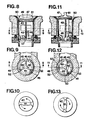
Les figures 8 à 13 montrent la deuxième forme d'exécution.
- La figure 8 est une coupe selon 8-8 de fig. 9, le clapet étant en position fermée.
- La figure 9 est une coupe selon 9-9 de fig. 8.
- La figure 10 est une vue en plan correspondant à la fig. 8.
- La figure 11 est une coupe selon 11-11 de fig. 12, le clapet étant ouvert.
- La figure 12 est une coupe selon 12-12 de fig. 11.
- La figure 13 est une vue en plan correspondant à la fig. 11.
- Figure 8 is a section along 8-8 of fig. 9, the valve being in the closed position.
- Figure 9 is a section on 9-9 of fig. 8.
- FIG. 10 is a plan view corresponding to FIG. 8.
- FIG. 11 is a section on 11-11 of FIG. 12, the valve being open.
- Figure 12 is a section along 12-12 of fig. 11.
- FIG. 13 is a plan view corresponding to FIG. 11.
On voit sur la figure 1 la partie 20 d'un appareil sanitaire qui comprend une bonde 22 et un canal 21 de vidage du "trop plein".We see in Figure 1 the
La bonde 22 est filetée et fixée à l'appareil sanitaire 20 grâce à un écrou de serrage 23 comprimant un joint d'étanchéité 24 contre la partie 20 de cet appareil. L'intérieur de la partie inférieure de la bonde 22 constitue un organe fixe, de forme générale cylindrique annulaire, dont la surface supérieure forme trois cames indentiques 25 que l'on voit aussi sous forme développée sur la figure 7. Chaque came 25, dont la surface de guidage est inclinée (par exemple à 45°) par rapport à l'axe et dans le sens de l'écoulement, donc vers l'intérieur de la bonde 22, afin d'éviter toute retenue de matière solide, présente une partie basse 26, un chemin de came 27, et une partie haute 28. La pente de cette partie haute 28 vue de face est nulle, voire légèrement inversée. Trois butées 29 agissant par deux de leurs faces sont disposées entre les cames 25 (figure 2). La surface supérieure des butées 29 est inclinée vers l'intérieur de même façon que les surfaces de cames 26, 27, 28.The
Le clapet 30 repose sur un siège fixe 31. Le contact est assuré par un joint annulaire 32. La tige verticale 33 de la soupape est formée par la jonction de trois éléments radiaux 34 dont au moins une partie 35 est formée d'un matériau autolubrifiant et résistant à l'usure et dont la partie inférieure oblique glisse sur les cames décrites précédemment. Dans la position représentée par la figure 1, le contact n'est pas établi entre les cames 25 et les éléments radiaux 34 et c'est la tête 30 du clapet qui repose sur son siège 31. D'autre part, les trois éléments radiaux 34 garantissent, en glissant avec jeu dans la bonde filetée 22, le maintien vertical du clapet en toute position, tout en favorisant l'écoulement de l'eau.The
Opère-t-on une rotation du clapet (en le saisissant par sa nervure 36) selon le sens indiqué par les flèches en figure 3, les parties 35 glissent le long des chemins de came 27, induisant ainsi le mouvement vertical du clapet vers la position ouverte que montrent les fig. 4 à 6.Is there a rotation of the valve (by grasping it by its rib 36) in the direction indicated by the arrows in FIG. 3, the
Lorsque les butées 29 empêchent la poursuite de la rotation, le clapet se trouve en position ouverte et peut être lâché. Sans autre intervention, il se maintient dans cette position (figures 4, 5 et 6).When the
Le degré d'ouverture du clapet est préréglé par le niveau de la surface 28 et par la longueur des éléments radiaux 34, de façon à empêcher le passage d'objets tels que bagues, bouchons de dentifrice ou autres.The degree of opening of the valve is preset by the level of the
Pour ramener le clapet 30 en position fermée, il suffit de la faire tourner en sens inverse, comme indiqué par les flèches sur la fig. 6, jusqu'à ce que les éléments radiaux 34 butent, à l'autre bout de leur course, contre les butées 29. En lâchant alors le clapet, celui-ci tombe en position de fermeture. Les éléments radiaux sont alors en effet légèrement distants des parties basses 26 des cames 25, comme on le voit sur la fig. 1.To return the
Si l'on saisit le clapet par sa nervure de préhension 36 et qu'on le tire verticalement vers le haut, on le dégage entièrement de la bonde 22, les éléments radiaux 34 pouvant se déplacer librement verticalement dans celleci. Ainsi on libère sans démontage un accès maximum à l'intérieur de la bonde et de l'organe fixe 25 pour des opérations de nettoyage.If one grasps the valve by its gripping
Comme on le voit sur les fig. 3 et 6, la position angulaire de la nervure 36 indique si le clapet est fermé ou ouvert.As seen in Figs. 3 and 6, the angular position of the
Dans la forme d'exécution selon fig. 8 à 13, les cames 25 sont remplacées par des surfaces d'appui 45 et des butées 46 correspondant aux butées 29. Les surfaces d'appui 45 sont à niveau constant mais inclinées vers l'intérieur, comme les surfaces de cames 26, 27, 28 de la première forme d'exécution. La surface supérieure des butées 46 est inclinée de même façon.In the embodiment according to fig. 8 to 13, the
Chaque surface d'appui 45 se termine à une extrémité par une butée 46 et à son extrémité opposée par une interruption 52.Each bearing
Comme dans la première forme d'exécution, le clapet 47 présente une tige formant trois éléments radiaux 48, un joint d'étanchéité 49 coopérant avec un siège 50, et une nervure de préhension et d'actionnement en rotation 51. Les éléments 48 présentent des parties 53 pareilles aux parties 35, prévues pour coopérer avec des surfaces d'appui coniques 45 d'une pièce 44 analogue à 25.As in the first embodiment, the
Le fonctionnement de cette seconde forme d'exécution est le suivant. Dans la position des organes selon fig. 8, 9 et 10, les éléments 48 sont dans les interruptions ou vides 52 et le clapet repose fermé sur son siège 50. Si l'on saisit la nervure 51, qu'on soulève le clapet 47 pour dégager les éléments 48 des vides 52 et qu'on le fait tourner dans le sens des flèches de la fig. 10, on amène ces éléments à buter contre les butées 46. On lâche alors la nervure 51, les parties 53 viennent reposer sur les surfaces d'appui 45 (si on les avait soulevées plus haut). Dès lors, le clapet est et reste ouvert. On se trouve alors dans la position illustrée par les fig. 11 à 13. Pour fermer le clapet, il suffit de le faire tourner dans le sens des flèches de la fig. 13, jusqu'à ce que les éléments 48 arrivent contre les butées 46 et tombent dans les interruptions ou vides 52 et l'on se retrouve dans la position selon fig. 8 à 10. Ainsi l'ouverture et la fermeture se font sans tâtonnement.The operation of this second embodiment is as follows. In the position of the organs according to fig. 8, 9 and 10, the
Claims (7)
Applications Claiming Priority (2)
| Application Number | Priority Date | Filing Date | Title |
|---|---|---|---|
| CH2554/85 | 1985-06-17 | ||
| CH255485 | 1985-06-17 |
Publications (1)
| Publication Number | Publication Date |
|---|---|
| EP0217738A1 true EP0217738A1 (en) | 1987-04-08 |
Family
ID=4236409
Family Applications (1)
| Application Number | Title | Priority Date | Filing Date |
|---|---|---|---|
| EP19860810100 Withdrawn EP0217738A1 (en) | 1985-06-17 | 1986-02-26 | Drain valve device for a sanitary installation |
Country Status (4)
| Country | Link |
|---|---|
| EP (1) | EP0217738A1 (en) |
| DE (1) | DE8606855U1 (en) |
| ES (1) | ES8703174A1 (en) |
| PT (1) | PT82567A (en) |
Families Citing this family (1)
| Publication number | Priority date | Publication date | Assignee | Title |
|---|---|---|---|---|
| WO1998054416A1 (en) * | 1997-05-27 | 1998-12-03 | Senova Ab | A floor drain |
Citations (6)
| Publication number | Priority date | Publication date | Assignee | Title |
|---|---|---|---|---|
| US1613251A (en) * | 1925-07-16 | 1927-01-04 | Lewis H Stead | Plumbing fixture |
| DE2722585A1 (en) * | 1976-05-27 | 1977-12-08 | Emco Ltd | CLOSURE FOR THE DRAIN OUTLET OF A BATHTUB, A WASHBASIN OR DGL. |
| US4143432A (en) * | 1976-05-21 | 1979-03-13 | Deken Frederick J | Adjustable drain plug |
| US4320540A (en) * | 1980-07-24 | 1982-03-23 | Waltec, Inc. | Discharge drain assembly |
| FR2528090A1 (en) * | 1982-06-03 | 1983-12-09 | Fonderie Soc Gen De | Drain plug for emptying basins etc. - comprises vertically displaceable plug actuated by rod pivoting in lower conical section |
| DE3320124A1 (en) * | 1983-06-03 | 1984-12-13 | Hans Grohe Gmbh & Co Kg, 7622 Schiltach | SANITARY DRAIN VALVE |
-
1986
- 1986-02-26 EP EP19860810100 patent/EP0217738A1/en not_active Withdrawn
- 1986-03-12 DE DE19868606855 patent/DE8606855U1/en not_active Expired
- 1986-05-12 PT PT8256786A patent/PT82567A/en not_active Application Discontinuation
- 1986-05-22 ES ES555207A patent/ES8703174A1/en not_active Expired
Patent Citations (6)
| Publication number | Priority date | Publication date | Assignee | Title |
|---|---|---|---|---|
| US1613251A (en) * | 1925-07-16 | 1927-01-04 | Lewis H Stead | Plumbing fixture |
| US4143432A (en) * | 1976-05-21 | 1979-03-13 | Deken Frederick J | Adjustable drain plug |
| DE2722585A1 (en) * | 1976-05-27 | 1977-12-08 | Emco Ltd | CLOSURE FOR THE DRAIN OUTLET OF A BATHTUB, A WASHBASIN OR DGL. |
| US4320540A (en) * | 1980-07-24 | 1982-03-23 | Waltec, Inc. | Discharge drain assembly |
| FR2528090A1 (en) * | 1982-06-03 | 1983-12-09 | Fonderie Soc Gen De | Drain plug for emptying basins etc. - comprises vertically displaceable plug actuated by rod pivoting in lower conical section |
| DE3320124A1 (en) * | 1983-06-03 | 1984-12-13 | Hans Grohe Gmbh & Co Kg, 7622 Schiltach | SANITARY DRAIN VALVE |
Also Published As
| Publication number | Publication date |
|---|---|
| ES555207A0 (en) | 1987-02-16 |
| ES8703174A1 (en) | 1987-02-16 |
| DE8606855U1 (en) | 1986-05-15 |
| PT82567A (en) | 1986-06-01 |
Similar Documents
| Publication | Publication Date | Title |
|---|---|---|
| FR2704525A1 (en) | Cap lock assembly. | |
| FR2936000A1 (en) | WATER HUNTING DEVICE, IN PARTICULAR FOR W.C. BOWL AND W.C. BOWL ASSEMBLY AND HUNTING DEVICE OBTAINED FROM WATER | |
| EP0217738A1 (en) | Drain valve device for a sanitary installation | |
| EP0486373B1 (en) | Drinker for cattle | |
| EP0124458B1 (en) | Flushing device for a flushing tank operated by a push button | |
| FR2606296A1 (en) | Rail for spraying a fluid | |
| EP0505840A1 (en) | Device for emptying a flushing cistern of a toilet room | |
| FR2831570A1 (en) | PUISARD TO DRAIN WATER FROM A PREMISES | |
| CH557493A (en) | Relief valve for water blocked toilet pipes - is screwed into cleaning socket and press. operated against spring | |
| FR2695910A1 (en) | Cover for beverage can with drinking mouthpiece or straw - comprises circular cover with downward edge flange and opening corresponding to can opening, adjustably receiving mouthpiece and/or straw | |
| WO1995017558A1 (en) | Water flush device with central guide for bathroom facilities | |
| EP0128847B1 (en) | Mechanism for the inversion of movements, and its application to draining devices for flushing tanks | |
| EP0209478A1 (en) | Inviolable push-button device for operating a flushing mechanism for flushing tanks | |
| FR2804143A1 (en) | Seal plug for water closet cistern cover has hinged lid fitting into plug adjacent to opening for flush actuator | |
| FR2494464A1 (en) | Auxiliary float chamber for toilet system for faster refilling - uses auxiliary float chamber which cannot fill until main cistern is full, thus holding inlet valve fully open, giving faster filling | |
| FR2724291A1 (en) | Watering tube for animals such as rabbits | |
| FR2907874A1 (en) | Water e.g. hot water, economizer for use during washing e.g. fruits, has pulse control device interrupting water flow when pulse is applied on outlet nozzle along flow axis, and restoring water flow when another pulse is applied on nozzle | |
| FR2682140A1 (en) | Device for controlling the volume of water released by a flush system | |
| CH251607A (en) | Valved drain plug for sanitary ware. | |
| FR2584436A1 (en) | FLOATING BELL HUNTING DEVICE FOR WATER HUNTING RESERVOIR. | |
| FR2842226A1 (en) | Device, for automatically closing valves used for filling reservoirs such as toilet cisterns, includes float movable along end part that is pivotally coupled via rod to vertical stand | |
| FR2653797A1 (en) | Controlled activating device for flushing valve | |
| FR2691189A1 (en) | Wash-basin drain plug with control lever - comprises flared top with threaded top and middle sections lever housed in collar screwed in opening and spherical bearing joint | |
| FR2693644A1 (en) | Bath or shower with access door for user - is opened or closed by hydraulic strut operated by handle joined to hydraulic regulator which is connected to strut by pipe | |
| FR2973817A1 (en) | Multifunctional passage for sanitation installation, has chamfer internally determining flat contour around input opening, and upper plate located between input opening and peripheral level |
Legal Events
| Date | Code | Title | Description |
|---|---|---|---|
| PUAI | Public reference made under article 153(3) epc to a published international application that has entered the european phase |
Free format text: ORIGINAL CODE: 0009012 |
|
| AK | Designated contracting states |
Kind code of ref document: A1 Designated state(s): AT CH DE FR GB IT LI NL SE |
|
| 17P | Request for examination filed |
Effective date: 19870706 |
|
| 17Q | First examination report despatched |
Effective date: 19880823 |
|
| STAA | Information on the status of an ep patent application or granted ep patent |
Free format text: STATUS: THE APPLICATION IS DEEMED TO BE WITHDRAWN |
|
| 18D | Application deemed to be withdrawn |
Effective date: 19891219 |
|
| RIN1 | Information on inventor provided before grant (corrected) |
Inventor name: OBERSON, ANDRE |