EP0124458B1 - Flushing device for a flushing tank operated by a push button - Google Patents
Flushing device for a flushing tank operated by a push button Download PDFInfo
- Publication number
- EP0124458B1 EP0124458B1 EP84430011A EP84430011A EP0124458B1 EP 0124458 B1 EP0124458 B1 EP 0124458B1 EP 84430011 A EP84430011 A EP 84430011A EP 84430011 A EP84430011 A EP 84430011A EP 0124458 B1 EP0124458 B1 EP 0124458B1
- Authority
- EP
- European Patent Office
- Prior art keywords
- push button
- flushing
- tank
- device operated
- rack
- Prior art date
- Legal status (The legal status is an assumption and is not a legal conclusion. Google has not performed a legal analysis and makes no representation as to the accuracy of the status listed.)
- Expired
Links
Images


Classifications
-
- E—FIXED CONSTRUCTIONS
- E03—WATER SUPPLY; SEWERAGE
- E03D—WATER-CLOSETS OR URINALS WITH FLUSHING DEVICES; FLUSHING VALVES THEREFOR
- E03D5/00—Special constructions of flushing devices, e.g. closed flushing system
- E03D5/02—Special constructions of flushing devices, e.g. closed flushing system operated mechanically or hydraulically (or pneumatically) also details such as push buttons, levers and pull-card therefor
- E03D5/09—Special constructions of flushing devices, e.g. closed flushing system operated mechanically or hydraulically (or pneumatically) also details such as push buttons, levers and pull-card therefor directly by the hand
-
- E—FIXED CONSTRUCTIONS
- E03—WATER SUPPLY; SEWERAGE
- E03D—WATER-CLOSETS OR URINALS WITH FLUSHING DEVICES; FLUSHING VALVES THEREFOR
- E03D1/00—Water flushing devices with cisterns ; Setting up a range of flushing devices or water-closets; Combinations of several flushing devices
- E03D1/02—High-level flushing systems
- E03D1/14—Cisterns discharging variable quantities of water also cisterns with bell siphons in combination with flushing valves
- E03D2001/147—Cisterns discharging variable quantities of water also cisterns with bell siphons in combination with flushing valves having provisions for active interruption of flushing
Definitions
- the present invention relates to an evacuation device controlled by a push button, for a flush tank.
- An objective targeted by the present invention is therefore, in particular, to remedy the aforementioned drawbacks of the systems for evacuating flushing cisterns provided with a control mechanism acting by pressing on a push button.
- this object is achieved by means of a device comprising a push button accessible from the outside of the tank, a movement reversal mechanism, a transmission member and a valve for closing the orifice. for emptying the tank, this device being notably remarkable in that said movement reversal mechanism comprises a first rack or drive rack secured by its upper part or by an extension of its upper part, of the push button and meshing with a pinion, which is also engaged with a second rack or driven rack subject to the transmission member carrying said shutter valve, so that the pressure exerted on the push button causes the valve to be raised shutter and opening of the drain orifice.
- the pinions of the pinion or of its axis are mounted with the ability to move in vertical openings that have a fixed support guide, while the lower portion of the rod carrying the shutter valve of the 'drain port is equipped with a float advantageously constituted by a bell arranged concentrically around said lower portion.
- This device comprises a push button 1, movable axially and vertically, for example over a stroke of the order of 15 mm.
- This push button comprises a central nut 1a constituted by a cylindrical axial stud provided with a blind thread, and a side skirt 1b, by means of which it is guided in and on a fixed setting button 2.
- This fixed button is secured to 'an envelope 3 constituted by a cylindrical sleeve.
- the rack 4 meshes with a pinion 5 which is also engaged with a second rack 6 housed with a longitudinal translational ability in the sleeve 3 and which is conventionally called "rack driven driven in the following description.
- the racks 4 and 6 are therefore arranged parallel and face to face. They are guided in a support guide 7 fixedly installed in the sleeve 3, for example by means of a pin 8.
- This support guide is constituted by a generally cylindrical part provided with two parallel grooves 7a, 7b diametrically opposite and separated by a partition 7c in which a window 7d is formed for the passage of the pinion 5.
- the pinion 5 is mounted with the ability to move in the vertical plane.
- the pins 5a of the pinion 5 or of its axis are housed with the ability to move in opposite vertical slots 7e, 7f, respectively, which has the support guide 7. These slots are provided in the opposite walls which delimit, laterally, the window 7d which has a length a little greater than that of said lights in order to allow the movements of the pinion.
- the driven rack 6 is subject, separably and adjustable, to the rod 9 carrying the valve 10 for closing the emptying orifice of the flush tank.
- the rack 6 is, for example, rigidly secured to a screw 6a arranged in the extension of its lower portion and formed in one piece with it.
- the screw 6a is screwed into a nut 9a which is equipped, axially, the top of the rod 9 which is constituted by a cylindrical tube. Thanks to this removable assembly method, the rack 6 and the tubular rod 9 are secured in translation.
- the valve 10 is constituted by a seal in the form of a circular crown installed in a peripheral groove which is provided with the lower end of the rod 9.
- the lower portion of the said rod is arranged so as to constitute a float.
- this float is formed by a bell 11 arranged around the lower portion of the rod 9 and the lower edge of which is placed above and at a reduced distance from the plane in which the upper face of the valve 10 is located. .
- the device according to the invention is also associated with a base 14 comprising a central orifice 0 constituting the emptying orifice of the reservoir and whose upper circular edge 14a forms the seat of the valve 10.
- This base of a design known per se, is intended to be installed fixedly, by means of a nut screwing on its threaded lower cylindrical portion 14b, on the discharge orifice 01 of the reservoir. It makes it possible to ensure the junction between said discharge orifice and the orifice for entering the rinsing water into the toilet bowl. It is able to be assembled, in a removable manner, to the bell-shaped base 12a of the casing or outer casing 12.
- the base comprises three locking forks 14c oriented upwards, arranged equidistantly around and at distance from the drain opening 0.
- a space is reserved between the vertical branches of these forks allowing the passage of the lower edge of the outer bell 12a resting in the bottom of said space, the locking being obtained by a rotation of the tubular casing 12 -12a for placing the outer shoulders 12b in the form of a circular arc which is provided with the base of said outer bell, below the retaining spout 14d directed inward which is provided with the outer branch of each fork.
- the push button 1 accessible from outside the tank is in the high position, while the valve 10 is pressed on its seat 14a.
- the drive rack 4 is pressed which communicates a rotational movement to the pinion 5 whose pins 5a remain maintained in the bottom of the vertical lights 7e, 7f.
- the rotation of the pinion causes an upward movement of the driven rack 6, of amplitude equal to that of the downward travel of the drive rack ( Figure 7).
- the upward translation of the driven rack causes a corresponding axial translation of the rod 9 and, consequently, the lifting of the valve 10.
- the upward thrust which is exerted on the float 11 allows 'move the valve a little further from its seat, so as to completely release the drain orifice 0 and allow an effective flushing action.
- This additional lifting of the valve 10 over a second stroke of the order of 15 mm is made possible by the fact that the pinion 5 driven by the additional upward stroke of the driven rack 6, can roll on the drive rack 4 immobilized by pressing the push button 1 on the fixed button 2, said pinion and its pins 5a moving, during this movement, in the window 7d and in the lights 7e, 7f, respectively.
- the stroke of the push button 1 is limited to 15 mm, while that of the assembly: 6-rod rack 9-valve 10, is 30 mm and constituted by two successive movements, each having an amplitude of 15 mm. These movements are accomplished in a very short period of time, the emptying process being initiated as soon as the push button is pressed, and then continuing automatically, without the possibility of interruption.
- valve 10 automatically returns to apply on its seat, the assembly 6-9-10 descending by gravity effect, by driving, in the first half of its downward travel, the descent of the pinion, then, during the second half of its travel, the ascent of the drive rack 4 and of the push button 1 integral with the latter.
Abstract
Description
La présente invention concerne un dispositif d'évacuation à commande par bouton-poussoir, pour réservoir de chasse d'eau.The present invention relates to an evacuation device controlled by a push button, for a flush tank.
On connaît (Brevet américain N° 3.968.525) des dispositifs d'évacuation des réservoirs de chasse d'eau, à commande par bouton-poussoir, comportant un bouton-poussoir agissant, lors de son enfoncement, sur un système d'inversion de mouvement comprenant un levier monté avec une aptitude de basculement sur un axe porteur, l'une des extrémités de ce levier recevant la poussée du bouton-poussoirtandis que son extrémité opposée est reliée au clapet d'obturation de l'orifice de vidange du réservoir, au moyen d'un organe de transmission constitué par une chaine ou une tige rigide.Are known (US Patent No. 3,968,525) devices for evacuating flushing cisterns, controlled by a push button, comprising a push button acting, when pressed, on a reversing system of movement comprising a lever mounted with a tilting ability on a load-bearing axis, one of the ends of this lever receiving the push of the push-button while its opposite end is connected to the shutter valve of the tank emptying orifice, by means of a transmission member constituted by a chain or a rigid rod.
De tels dispositifs conçus pour supplanter les systèmes d'évacuation dotés d'un bouton de commande agissant par traction (lequel présente notamment le désavantage d'être très exposé à des risques d'arrachement), sont affectés d'un certain nombre d'inconvénients qui constituent certainement des obstacles à la progression de leur vulgarisation. Ces inconvénients résident notamment :
- dans le fait que tous les systèmes d'évacuation à commande par bouton-poussoir connus sont relativement encombrants, ce qui n'est pas propice si l'on considère l'espace réduit dont on dispose à l'intérieur du réservoir, le volume d'eau souhaitable pour obtenir un processus de chasse d'eau efficace et la nécessité de loger également, dans ledit réservoir, le robinet à flotteur commandant l'admission d'eau ;
- dans le fait qu'il est nécessaire de prévoir un agencement spécial du réservoir pour l'installation de l'axe portant le levier pivotant ;
- dans le fait que certaines de leurs pièces mobiles sont orientées dans différentes directions et se déplacent suivant des trajectoires non parallèles, de sorte qu'elles ne sont pas parfaitement guidées, ce qui peut être une cause de fonctionnement défectueux ;
- dans le fait qu'il est nécessaire de maintenir la pression sur le bouton-poussoir durant le processus de chasse d'eau, et qu'il est possible d'interrompre ce processus en relâchant cette pression, ce qui est incompatible avec les règles d'hygiène modernes.
- in that all of the known push-button control evacuation systems are relatively bulky, which is not conducive if we consider the reduced space available within the tank, the volume d water desirable to obtain an efficient flushing process and the need to also house, in said tank, the float valve controlling the admission of water;
- in the fact that it is necessary to provide a special arrangement of the reservoir for the installation of the axis carrying the pivoting lever;
- in that some of their moving parts are oriented in different directions and move in non-parallel paths, so that they are not perfectly guided, which can be a cause of faulty operation;
- in the fact that it is necessary to maintain pressure on the push button during the flushing process, and that it is possible to interrupt this process by releasing this pressure, which is incompatible with the rules of hygiene.
Un objectif visé par la présente invention est donc, notamment, de remédier aux inconvénients susmentionnés des systèmes d'évacuation des réservoirs de chasse d'eau dotés d'un mécanisme de commande agissant par pression sur un bouton-poussoir.An objective targeted by the present invention is therefore, in particular, to remedy the aforementioned drawbacks of the systems for evacuating flushing cisterns provided with a control mechanism acting by pressing on a push button.
Selon l'invention, ce but est atteint au moyen d'un dispositif comprenant un bouton-poussoir accessible de l'extérieur du réservoir, un mécanisme d'inversion de mouvement, un organe de transmission et un clapet d'obturation de l'orifice de vidange du réservoir, ce dispositif étant notamment remarquable par le fait que ledit mécanisme d'inversion de mouvement comprend une première crémaillère ou crémaillère d'entraînement solidaire, par sa partie supérieure ou par un prolongement de sa partie supérieure, du bouton-poussoir et engrenant avec un pignon, lequel est également en prise avec une seconde crémaillère ou crémaillère entraînée assujettie à l'organe de transmission portant ledit clapet d'obturation, de sorte que l'appui exercé sur le bouton-poussoir entraîne le soulèvement du clapet d'obturation et l'ouverture de l'orifice de vidange.According to the invention, this object is achieved by means of a device comprising a push button accessible from the outside of the tank, a movement reversal mechanism, a transmission member and a valve for closing the orifice. for emptying the tank, this device being notably remarkable in that said movement reversal mechanism comprises a first rack or drive rack secured by its upper part or by an extension of its upper part, of the push button and meshing with a pinion, which is also engaged with a second rack or driven rack subject to the transmission member carrying said shutter valve, so that the pressure exerted on the push button causes the valve to be raised shutter and opening of the drain orifice.
Selon une autre disposition caractérisante, les tourillons du pignon ou de son axe, sont montés avec une aptitude de déplacement dans des lumières verticales que présente un guide-support fixe, tandis que la portion inférieure de la tige portant le clapet d'obturation de l'orifice de vidange est équipée d'un flotteur avantageusement constitué par une cloche disposée concentriquement autour de ladite portion inférieure.According to another characterizing arrangement, the pinions of the pinion or of its axis, are mounted with the ability to move in vertical openings that have a fixed support guide, while the lower portion of the rod carrying the shutter valve of the 'drain port is equipped with a float advantageously constituted by a bell arranged concentrically around said lower portion.
Le dispositif à bouton-poussoir selon l'invention procure plusieurs avantages tels que, par exemple :
- un encombrement réduit, compte tenu du fait que tous ses organes ou groupes d'organes constitutifs sont rassemblés sur un axe commun ;
- l'inutilité d'un agencement particulier du réservoir, de sorte que ce dispositif peut être facilement et avantageusement substitué aux systèmes d'évacuation comportant un bouton de commande agissant par traction et déjà installés sur des réservoirs en service ;
- un fonctionnement sûr et de longue durée résultant du fait que tous ses organes mobiles se déplacent suivant des trajectoires parallèles et sont parfaitement guidés ;
- l'impossibilité d'interrompre le processus de rinçage lorsque ce dernier a été amorcé, ce qui respecte les normes d'hygiène actuelles.
- reduced dimensions, taking into account the fact that all of its constituent organs or groups of organs are brought together on a common axis;
- the uselessness of a particular arrangement of the tank, so that this device can be easily and advantageously substituted for the drainage systems comprising a control button acting by traction and already installed on tanks in service;
- safe and long-term operation resulting from the fact that all of its movable members move in parallel paths and are perfectly guided;
- the impossibility of interrupting the rinsing process when it has started, which meets current hygiene standards.
Les buts, caractéristiques et avantages ci-dessus, et d'autres encore, ressortiront mieux de la description qui suit et des dessins annexés dans lesquels :
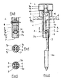
- La figure 1 est une vue en coupe axiale partielle du dispositif d'évacuation de réservoir de chasse d'eau à commande par bouton-poussoir selon l'invention, lequel est illustré dans une position correspondant à la fermeture dudit dispositif.
- La figure 2 est une vue en coupe axiale du seul mécanisme à commande par bouton-poussoir de ce dispositif, montré positionné sur le couvercle, partiellement représenté, d'un réservoir de chasse d'eau.
- La figure 3 est une vue en coupe verticale selon la ligne 3-3 de la figure 2.
- La figure 4 est une vue en plan et en coupe selon la ligne 4-4 de la figure 2.
- La figure 5 est une vue en plan et en coupe suivant la ligne 5-5 de la figure 2.
- Les figures 6 à 8 sont des vues partielles, en coupe axiale, illustrant le fonctionnement du dispositif selon l'invention.
- Figure 1 is a partial axial sectional view of the flushing device for flushing the toilet tank by push button control according to the invention, which is illustrated in a position corresponding to the closing of said device.
- Figure 2 is an axial sectional view of the single push button control mechanism of this device, shown positioned on the cover, partially shown, of a flush tank.
- Figure 3 is a vertical sectional view along line 3-3 of Figure 2.
- FIG. 4 is a plan view and in section along line 4-4 of FIG. 2.
- FIG. 5 is a plan view and in section along line 5-5 of FIG. 2.
- Figures 6 to 8 are partial views, in axial section, illustrating the operation of the device according to the invention.
On se réfère auxdits dessins pour décrire un mode d'exécution avantageux, quoique nullement limitatif, du dispositif selon l'invention.Reference is made to said drawings to describe an advantageous, although in no way limiting, embodiment of the device according to the invention.
Ce dispositif comprend un bouton-poussoir 1, mobile axialement et verticalement, par exemple sur une course de l'ordre de 15 mm. Ce bouton-poussoir comporte un écrou central 1a constitué par un téton axial cylindrique doté d'un taraudage borgne, et une jupe latérale 1b, au moyen desquels il est guidé dans et sur un bouton de calage fixe 2. Ce bouton fixe est solidaire d'une enveloppe 3 constituée par un manchon cylindrique.This device comprises a
De manière avantageuse, le bouton fixe 2 et le manchon 3 sont assemblés par vissage, ledit bouton fixe et la portion supérieure dudit manchon comportant, respectivement, à cet effet, un taraudage et un filetage complémentaires. D'autre part, le manchon 3 est disposé verticalement et il est doté d'un filetage extérieur sur au moins sa portion inférieure. A l'intérieur dudit manchon 3, est logé un mécanisme d'inversion de mouvement. Ce mécanisme comprend une première crémaillère verticale 4 que l'on nomme conventionnellement « crémaillère d'entraînement dans la suite du présent exposé, cette crémaillère étant solidaire, en translation, par sa partie supérieure ou par un prolongement de sa partie supérieure, du bouton-poussoir mobile 1. La crémaillère d'entraînement et ledit bouton-poussoir sont, de préférence, assemblés de manière séparable, par vissage, l'extrémité supérieure de ladite crémaillère étant, par exemple, formée d'une seule pièce avec une vis 4a vissée dans l'écrou central la du bouton-poussoir.Advantageously, the
La crémaillère 4 engrène avec un pignon 5 qui est également en prise avec une seconde crémaillère 6 logée avec une aptitude de translation longitudinale dans le manchon 3 et que l'on appelle conventionnellement « crémaillère entraînée dans la suite de la description. Les crémaillères 4 et 6 sont donc disposées parallèlement et face à face. Elles sont guidées dans un guide-support 7 installé fixement dans le manchon 3, par exemple au moyen d'une goupille 8. Ce guide-support est constitué par une pièce de forme générale cylindrique dotée de deux rainures parallèles 7a, 7b diamétralement opposées et séparées par une cloison 7c dans laquelle est ménagée une fenêtre 7d pour le passage du pignon 5.The
Selon une autre caractéristique importante de l'invention et dont l'intérêt est expliqué dans la suite du présent exposé, le pignon 5 est monté avec une aptitude de déplacement dans le plan vertical. Suivant un mode d'exécution intéressant, les tourillons 5a du pignon 5 ou de son axe sont logés avec une aptitude de déplacement dans des lumières verticales opposées 7e, 7f, respectivement, que présente le guide-support 7. Ces lumières sont ménagées dans les parois opposées qui délimitent, latéralement, la fenêtre 7d laquelle a une longueur un peu plus importante que celle desdites lumières afin d'autoriser les déplacements du pignon.According to another important characteristic of the invention and the advantage of which is explained in the remainder of this description, the
La crémaillère entraînée 6 est assujettie, de manière séparable et réglable, à la tige 9 portant le clapet 10 d'obturation de l'orifice de vidange du réservoir de la chasse d'eau. La crémaillère 6 est, par exemple, rigidement solidaire d'une vis 6a disposée dans le prolongement de sa portion inférieure et formée d'une seule pièce avec celle-ci.The driven
La vis 6a est vissée dans un écrou 9a dont est équipé, axialement, le sommet de la tige 9 laquelle est constituée par un tube cylindrique. Grâce à ce mode d'assemblage démontable, la crémaillère 6 et la tige tubulaire 9 sont solidaires en translation.The screw 6a is screwed into a nut 9a which is equipped, axially, the top of the
Le clapet 10 est constitué par un joint d'étanchéité en forme de couronne circulaire installé dans une gorge périphérique dont est pourvue, l'extrémité inférieure de la tige 9. La portion inférieure de ladite tige est agencée de manière à constituer un flotteur. De façon connue en soi, ce flotteur est formé par une cloche 11 disposée autour de la portion basse de la tige 9 et dont le bord inférieur est placé au-dessus et à distance réduite du plan dans lequel se trouve la face supérieure du clapet 10.The
La partie inférieure du mécanisme d'inversion de mouvement et la tige-flotteur porte-clapet sont logées dans un carter tubulaire de protection et de guidage 12. L'extrémité supérieure de ce carter est équipée d'un chapeau 13 pourvu d'un orifice axial taraudé 13a constituant un écrou dans lequel est vissé le manchon 3 contenant le mécanisme d'inversion de mouvement.The lower part of the movement reversing mechanism and the valve holder float rod are housed in a tubular protection and
Au dispositif selon l'invention, est encore associé un culot 14 comportant un orifice central 0 constituant l'orifice de vidange du réservoir et dont le bord circulaire supérieur 14a forme le siège du clapet 10. Ce culot, de conception connue en soi, est destiné à être installé fixement, au moyen d'un écrou se vissant sur sa portion cylindrique inférieure filetée 14b, sur l'orifice d'évacuation 01 du réservoir. Il permet d'assurer la jonction entre ledit orifice d'évacuation et l'orifice d'entrée de l'eau de rinçage dans la cuvette du cabinet d'aisances. Il est apte à être assemblé, de manière amovible, à la base en forme de cloche 12a du carter ou enveloppe extérieure 12. Dans ce but, le culot comporte trois fourchettes de verrouillage 14c orientées vers le haut, disposées de manière équidistante autour et à distance de l'orifice de vidange 0. Entre les branches verticales de ces fourchettes, est réservé un espace permettant le passage du bord inférieur de la cloche extérieure 12a reposant dans le fond dudit espace, le verrouillage étant obtenu par une rotation du carter tubulaire 12-12a permettant de placer les épaulements extérieurs 12b en forme d'arc de cercle dont est pourvue la base de ladite cloche extérieure, au-dessous du bec de retenue 14d dirigé vers l'intérieur dont est dotée la branche extérieure de chaque fourchette.The device according to the invention is also associated with a
Lorsque le dispositif d'évacuation à commande par bouton-poussoir selon l'invention est installé dans un réservoir, il est assemblé, à l'aide des moyens précédemment décrits, au culot 14 positionné dans l'orifice d'évacuation 01 que présente le fond 15 du réservoir (partiellement représenté à la figure 1), tandis que la portion supérieure du manchon 3 traverse l'orifice 02 ménagé dans le couvercle 16 (partiellement illustré aux figures 1, 2, 6, 7 et 8) dudit réservoir, et que le bouton fixe 2 vissé sur ladite portion supérieure prend appui sur la face supérieure dudit couvercle. On observe que grâce à l'assemblage par vissage, d'une part, du manchon 3 et du carter tubulaire 12, et, d'autre part, de la vis 6a de la crémaillère entraînée 6 et de la tige porte-clapet 9, il est possible d'adapter aisément, par une simple rotation du mécanisme de commande à bouton-poussoir, la hauteur du dispositif d'évacuation selon l'invention à la profondeur du réservoir de chasse d'eau ; les filetages dudit manchon et de ladite vis ayant, dans ce but, un pas et un sens identiques.When the evacuation device controlled by a push button according to the invention is installed in a tank, it is assembled, using the means described above, to the base 14 positioned in the evacuation orifice 01 that has the bottom 15 of the reservoir (partially shown in FIG. 1), while the upper portion of the
On conçoit bien, après l'exposé qui précède, le fonctionnement du dispositif à bouton-poussoir selon l'invention.It is well understood, after the foregoing description, the operation of the push button device according to the invention.
En phases de remplissage et d'inactivité (figures 1 et 6), le bouton-poussoir 1 accessible de l'extérieur du réservoir est en position haute, tandis que le clapet 10 est appuyé sur son siège 14a. En appuyant sur le bouton-poussoir 1 sur une course de l'ordre de 15 mm, on enfonce la crémaillère d'entraînement 4 laquelle communique un mouvement de rotation au pignon 5 dont les tourillons 5a restent maintenus dans le fond des lumières verticales 7e, 7f. La rotation du pignon provoque un mouvement ascendant de la crémaillère entraînée 6, d'amplitude égale à celle de la course descendante de la crémaillère d'entraînement (figure 7).In filling and inactivity phases (Figures 1 and 6), the
La translation ascendante de la crémaillère entraînée provoque une translation axiale correspondante de la tige 9 et, par conséquent, le soulèvement du clapet 10. Lorsque ce dernier est décollé de son siège 14a, la poussée ascendante qui s'exerce sur le flotteur 11 permet d'éloigner un peu plus ledit clapet de son siège, de façon à dégager complètement l'orifice de vidange 0 et permettre une action de chasse d'eau efficace. Ce soulèvement supplémentaire du clapet 10 sur une seconde course de l'ordre de 15 mm est rendu possible par le fait que le pignon 5 entraîné par la course ascendante supplémentaire de la crémaillère entraînée 6, peut rouler sur la crémaillère d'entraînement 4 immobilisée par l'appui du bouton-poussoir 1 sur le bouton fixe 2, ledit pignon et ses tourillons 5a se déplaçant, lors de ce mouvement, dans la fenêtre 7d et dans les lumières 7e, 7f, respectivement. On comprend donc que, grâce au dispositif selon l'invention, la course du bouton-poussoir 1 est limitée à 15 mm, tandis que celle de l'ensemble : crémaillère 6-tige 9-clapet 10, est de 30 mm et constituée par deux mouvements successifs ayant chacun une amplitude de 15 mm. Ces mouvements s'accomplissent dans un laps de temps très court, le processus de vidange se trouvant amorcé dès que l'on appuie sur le bouton-poussoir, et se poursuivant ensuite automatiquement, sans possibilité d'interruption.The upward translation of the driven rack causes a corresponding axial translation of the
A la fin du processus de vidange durant l'accomplissement duquel il n'est pas nécessaire de maintenir l'appui sur le bouton-poussoir, le clapet 10 revient automatiquement s'appliquer sur son siège, l'ensemble 6-9-10 redescendant par effet de gravité, en entraînant, dans la première moitié de sa course descendante, la descente du pignon, puis, lors de la seconde moitié de sa course, la remontée de la crémaillère d'entraînement 4 et du bouton-poussoir 1 solidaire de cette dernière.At the end of the emptying process during which it is not necessary to keep pressing the push button, the
Claims (10)
Priority Applications (1)
| Application Number | Priority Date | Filing Date | Title |
|---|---|---|---|
| AT84430011T ATE29544T1 (en) | 1983-04-07 | 1984-04-05 | FLUSHING DEVICE FOR A CISTERN TO BE ACTUATED BY A PUSH BUTTON. |
Applications Claiming Priority (2)
| Application Number | Priority Date | Filing Date | Title |
|---|---|---|---|
| FR8305817A FR2543990B1 (en) | 1983-04-07 | 1983-04-07 | PUSH BUTTON CONTROLLED DISCHARGE DEVICE FOR A WATER FLUSHING TANK |
| FR8305817 | 1983-04-07 |
Publications (2)
| Publication Number | Publication Date |
|---|---|
| EP0124458A1 EP0124458A1 (en) | 1984-11-07 |
| EP0124458B1 true EP0124458B1 (en) | 1987-09-09 |
Family
ID=9287677
Family Applications (1)
| Application Number | Title | Priority Date | Filing Date |
|---|---|---|---|
| EP84430011A Expired EP0124458B1 (en) | 1983-04-07 | 1984-04-05 | Flushing device for a flushing tank operated by a push button |
Country Status (4)
| Country | Link |
|---|---|
| EP (1) | EP0124458B1 (en) |
| AT (1) | ATE29544T1 (en) |
| DE (1) | DE3466028D1 (en) |
| FR (1) | FR2543990B1 (en) |
Families Citing this family (7)
| Publication number | Priority date | Publication date | Assignee | Title |
|---|---|---|---|---|
| FR2591250B1 (en) * | 1985-03-19 | 1987-11-20 | Spmp Sa | PUSH BUTTON CONTROLLED HUNTING DEVICE FOR WATER HUNTING TANK |
| FR2584751B1 (en) * | 1985-07-09 | 1987-10-16 | Spmp Sa | INVIOLABLE PUSH-BUTTON DEVICE FOR CONTROLLING HUNTING MECHANISMS OF WATER HUNTING TANKS |
| FR2658219B1 (en) * | 1990-02-15 | 1992-05-22 | Spmp Sa | HUNTING MECHANISM WITH PUSH-BUTTON CONTROL AND CONTROLABLE ACTION. |
| FR2658844B1 (en) * | 1990-02-23 | 1994-01-21 | Matieres Plastiques Ste Phoceenn | HUNTING MECHANISM WITH PUSH BUTTON CONTROL AND SUBMERSIBLE FLOAT. |
| FR2673656B1 (en) * | 1991-03-05 | 1993-06-11 | Spmp | IMPROVED SANITARY WATER FLUSHING SYSTEM TO SAVE HUNTING WATER. |
| ES2117903B1 (en) * | 1992-11-12 | 1999-03-16 | Agullo Pablo Fominaya | IMPROVEMENTS INTRODUCED IN THE PATENT OF INVENTION NO. P-9202287/1, FOR: IMPROVEMENTS IN TOILET UNLOADERS FOR TOILETS. |
| DE9317693U1 (en) * | 1993-01-06 | 1994-01-27 | Geberit Ag | Extension rod for a cistern |
Family Cites Families (3)
| Publication number | Priority date | Publication date | Assignee | Title |
|---|---|---|---|---|
| US2431640A (en) * | 1945-06-09 | 1947-11-25 | Gordon Arthur | Automatic sewer flood control |
| CH349554A (en) * | 1957-08-15 | 1960-10-15 | Shires & Co London Limited | Toilet flush |
| US3968525A (en) * | 1974-12-05 | 1976-07-13 | Universal-Rundle Corporation | Actuating means for water closet flush tank |
-
1983
- 1983-04-07 FR FR8305817A patent/FR2543990B1/en not_active Expired
-
1984
- 1984-04-05 AT AT84430011T patent/ATE29544T1/en not_active IP Right Cessation
- 1984-04-05 EP EP84430011A patent/EP0124458B1/en not_active Expired
- 1984-04-05 DE DE8484430011T patent/DE3466028D1/en not_active Expired
Also Published As
| Publication number | Publication date |
|---|---|
| DE3466028D1 (en) | 1987-10-15 |
| EP0124458A1 (en) | 1984-11-07 |
| FR2543990B1 (en) | 1986-09-19 |
| FR2543990A1 (en) | 1984-10-12 |
| ATE29544T1 (en) | 1987-09-15 |
Similar Documents
| Publication | Publication Date | Title |
|---|---|---|
| EP0528740B1 (en) | Dual control flushing mechanism, selectively emptying the cistern partially or completely | |
| EP0520114B1 (en) | Interruptable flushing mechanism with garanteed minimum flush | |
| EP2334875B1 (en) | Flushing device, particularly for a toilet bowl, and resulting toilet bowl and flushing device assembly | |
| EP0124458B1 (en) | Flushing device for a flushing tank operated by a push button | |
| WO1998009558A1 (en) | Infusing apparatus | |
| EP0522218B1 (en) | Push-button flushing mechanism with submersible float | |
| EP0311542A1 (en) | Mechanism for activating the flushing of a toilet by a push button | |
| FR2658219A1 (en) | Flush mechanism with push-button control and with controllable action | |
| EP0128847B1 (en) | Mechanism for the inversion of movements, and its application to draining devices for flushing tanks | |
| WO1997017503A1 (en) | Dual cistern flush control device | |
| EP0209477B1 (en) | Flushing device having a floating siphon bell for flushing tanks | |
| FR2591250A1 (en) | Flushing device controlled by push-button for water flushing tank | |
| FR2698645A1 (en) | Interruptable toilet flush mechanism - has tilting cams which move along slots to raise moving part and push stopper valve away from seating | |
| EP0381576B1 (en) | Drain plug for sanitary appliances | |
| FR2678300A1 (en) | Water flush with two filling levels | |
| EP0209478B1 (en) | Inviolable push-button device for operating a flushing mechanism for flushing tanks | |
| FR2591212A1 (en) | CAPPER-FORMING DEVICE, IN PARTICULAR FOR A SMALLER WINE BOTTLE, SUCH AS CHAMPAGNE | |
| FR2751678A1 (en) | Automatic flushing system for toilet bowl in self=contained cabin | |
| FR2660679A1 (en) | Control device with push-button and tilting cam for flushing mechanism | |
| FR2519566A1 (en) | Cleaning appts. for cylindrical filter cartridges - which are simultaneously rotated and cleaned by jets of cleaning liq. in tank | |
| EP3937738B1 (en) | Machine for preparing infused beverages provided with a lift-up filter basket | |
| FR2684705A1 (en) | Flush device | |
| FR2804143A1 (en) | Seal plug for water closet cistern cover has hinged lid fitting into plug adjacent to opening for flush actuator | |
| EP0893544A1 (en) | Flushing device, especially for toilet bowls | |
| WO1995017558A1 (en) | Water flush device with central guide for bathroom facilities |
Legal Events
| Date | Code | Title | Description |
|---|---|---|---|
| PUAI | Public reference made under article 153(3) epc to a published international application that has entered the european phase |
Free format text: ORIGINAL CODE: 0009012 |
|
| AK | Designated contracting states |
Designated state(s): AT BE CH DE FR GB IT LI LU NL SE |
|
| 17P | Request for examination filed |
Effective date: 19841220 |
|
| GRAA | (expected) grant |
Free format text: ORIGINAL CODE: 0009210 |
|
| AK | Designated contracting states |
Kind code of ref document: B1 Designated state(s): AT BE CH DE FR GB IT LI LU NL SE |
|
| PG25 | Lapsed in a contracting state [announced via postgrant information from national office to epo] |
Ref country code: NL Effective date: 19870909 Ref country code: IT Free format text: LAPSE BECAUSE OF FAILURE TO SUBMIT A TRANSLATION OF THE DESCRIPTION OR TO PAY THE FEE WITHIN THE PRESCRIBED TIME-LIMIT;WARNING: LAPSES OF ITALIAN PATENTS WITH EFFECTIVE DATE BEFORE 2007 MAY HAVE OCCURRED AT ANY TIME BEFORE 2007. THE CORRECT EFFECTIVE DATE MAY BE DIFFERENT FROM THE ONE RECORDED. Effective date: 19870909 Ref country code: AT Effective date: 19870909 |
|
| REF | Corresponds to: |
Ref document number: 29544 Country of ref document: AT Date of ref document: 19870915 Kind code of ref document: T |
|
| PG25 | Lapsed in a contracting state [announced via postgrant information from national office to epo] |
Ref country code: SE Effective date: 19870930 |
|
| REF | Corresponds to: |
Ref document number: 3466028 Country of ref document: DE Date of ref document: 19871015 |
|
| NLV1 | Nl: lapsed or annulled due to failure to fulfill the requirements of art. 29p and 29m of the patents act | ||
| GBV | Gb: ep patent (uk) treated as always having been void in accordance with gb section 77(7)/1977 [no translation filed] | ||
| PG25 | Lapsed in a contracting state [announced via postgrant information from national office to epo] |
Ref country code: LU Free format text: LAPSE BECAUSE OF NON-PAYMENT OF DUE FEES Effective date: 19880430 |
|
| PLBE | No opposition filed within time limit |
Free format text: ORIGINAL CODE: 0009261 |
|
| STAA | Information on the status of an ep patent application or granted ep patent |
Free format text: STATUS: NO OPPOSITION FILED WITHIN TIME LIMIT |
|
| 26N | No opposition filed | ||
| PG25 | Lapsed in a contracting state [announced via postgrant information from national office to epo] |
Ref country code: GB Free format text: LAPSE BECAUSE OF NON-PAYMENT OF DUE FEES Effective date: 19881122 |
|
| PGFP | Annual fee paid to national office [announced via postgrant information from national office to epo] |
Ref country code: BE Payment date: 19910329 Year of fee payment: 8 |
|
| PGFP | Annual fee paid to national office [announced via postgrant information from national office to epo] |
Ref country code: DE Payment date: 19910412 Year of fee payment: 8 |
|
| PGFP | Annual fee paid to national office [announced via postgrant information from national office to epo] |
Ref country code: CH Payment date: 19910415 Year of fee payment: 8 |
|
| PG25 | Lapsed in a contracting state [announced via postgrant information from national office to epo] |
Ref country code: LI Effective date: 19920430 Ref country code: CH Effective date: 19920430 Ref country code: BE Effective date: 19920430 |
|
| BERE | Be: lapsed |
Owner name: SOC. PHOCEENNE DE MATIERES PLASTIQUES S P M P S.A Effective date: 19920430 |
|
| REG | Reference to a national code |
Ref country code: CH Ref legal event code: PL |
|
| PG25 | Lapsed in a contracting state [announced via postgrant information from national office to epo] |
Ref country code: DE Effective date: 19930101 |
|
| PGFP | Annual fee paid to national office [announced via postgrant information from national office to epo] |
Ref country code: FR Payment date: 19940428 Year of fee payment: 11 |
|
| PG25 | Lapsed in a contracting state [announced via postgrant information from national office to epo] |
Ref country code: FR Effective date: 19951229 |
|
| REG | Reference to a national code |
Ref country code: FR Ref legal event code: ST |