EP0217690A2 - Verfahren und Apparat zur Bestimmung des Trübungspunktes und des Stockpunktes - Google Patents
Verfahren und Apparat zur Bestimmung des Trübungspunktes und des Stockpunktes Download PDFInfo
- Publication number
- EP0217690A2 EP0217690A2 EP86401806A EP86401806A EP0217690A2 EP 0217690 A2 EP0217690 A2 EP 0217690A2 EP 86401806 A EP86401806 A EP 86401806A EP 86401806 A EP86401806 A EP 86401806A EP 0217690 A2 EP0217690 A2 EP 0217690A2
- Authority
- EP
- European Patent Office
- Prior art keywords
- liquid
- curve
- curves
- temperature
- slope
- Prior art date
- Legal status (The legal status is an assumption and is not a legal conclusion. Google has not performed a legal analysis and makes no representation as to the accuracy of the status listed.)
- Ceased
Links
- 238000000034 method Methods 0.000 title claims abstract description 10
- 239000007788 liquid Substances 0.000 claims abstract description 37
- 238000001816 cooling Methods 0.000 claims abstract description 9
- 238000012360 testing method Methods 0.000 claims description 18
- 239000000523 sample Substances 0.000 claims description 16
- 238000001514 detection method Methods 0.000 claims description 6
- 230000001186 cumulative effect Effects 0.000 claims description 2
- 230000002093 peripheral effect Effects 0.000 claims description 2
- 230000000750 progressive effect Effects 0.000 claims 1
- 238000002425 crystallisation Methods 0.000 description 4
- 230000008025 crystallization Effects 0.000 description 4
- 239000003921 oil Substances 0.000 description 4
- 239000003507 refrigerant Substances 0.000 description 3
- 230000015572 biosynthetic process Effects 0.000 description 2
- 238000010586 diagram Methods 0.000 description 2
- 230000000694 effects Effects 0.000 description 2
- 239000000446 fuel Substances 0.000 description 2
- 229930195733 hydrocarbon Natural products 0.000 description 2
- 150000002430 hydrocarbons Chemical class 0.000 description 2
- 239000010687 lubricating oil Substances 0.000 description 2
- -1 polytetrafluoroethylene Polymers 0.000 description 2
- 229920001343 polytetrafluoroethylene Polymers 0.000 description 2
- 239000004810 polytetrafluoroethylene Substances 0.000 description 2
- 239000007790 solid phase Substances 0.000 description 2
- 230000002411 adverse Effects 0.000 description 1
- 238000009529 body temperature measurement Methods 0.000 description 1
- 239000010779 crude oil Substances 0.000 description 1
- 230000008014 freezing Effects 0.000 description 1
- 238000007710 freezing Methods 0.000 description 1
- 239000011521 glass Substances 0.000 description 1
- 238000009413 insulation Methods 0.000 description 1
- 230000001050 lubricating effect Effects 0.000 description 1
- 238000005259 measurement Methods 0.000 description 1
- 239000003595 mist Substances 0.000 description 1
- 239000000203 mixture Substances 0.000 description 1
- 230000003071 parasitic effect Effects 0.000 description 1
- 239000003209 petroleum derivative Substances 0.000 description 1
- 239000004033 plastic Substances 0.000 description 1
- 238000003825 pressing Methods 0.000 description 1
- 238000012545 processing Methods 0.000 description 1
- 239000007787 solid Substances 0.000 description 1
- 230000008023 solidification Effects 0.000 description 1
- 238000007711 solidification Methods 0.000 description 1
- 125000006850 spacer group Chemical group 0.000 description 1
- 238000010561 standard procedure Methods 0.000 description 1
- 238000003756 stirring Methods 0.000 description 1
- 238000012546 transfer Methods 0.000 description 1
- 230000000007 visual effect Effects 0.000 description 1
Images
Classifications
-
- G—PHYSICS
- G01—MEASURING; TESTING
- G01N—INVESTIGATING OR ANALYSING MATERIALS BY DETERMINING THEIR CHEMICAL OR PHYSICAL PROPERTIES
- G01N25/00—Investigating or analyzing materials by the use of thermal means
- G01N25/02—Investigating or analyzing materials by the use of thermal means by investigating changes of state or changes of phase; by investigating sintering
- G01N25/04—Investigating or analyzing materials by the use of thermal means by investigating changes of state or changes of phase; by investigating sintering of melting point; of freezing point; of softening point
-
- G—PHYSICS
- G01—MEASURING; TESTING
- G01N—INVESTIGATING OR ANALYSING MATERIALS BY DETERMINING THEIR CHEMICAL OR PHYSICAL PROPERTIES
- G01N33/00—Investigating or analysing materials by specific methods not covered by groups G01N1/00 - G01N31/00
- G01N33/26—Oils; Viscous liquids; Paints; Inks
- G01N33/28—Oils, i.e. hydrocarbon liquids
- G01N33/2811—Oils, i.e. hydrocarbon liquids by measuring cloud point or pour point of oils
Definitions
- the invention relates to an improved method and apparatus for determining the cloud point and the pour point of various liquids, in particular mixtures of hydrocarbons comprising fuels, lubricating oils and crude oils.
- the invention can also be applied to the determination of the starting crystallization temperature and that of the freezing point of liquids.
- the determination of the cloud point and that of flow of petroleum products is defined by the French standard T 60-105, in particular for lubricating or combustible oils and gas oils.
- This standard also describes an apparatus of particular dimensions and shape for the application of the standard operating mode.
- the device includes a cooling bath, into which immerses vertically a glass test tube; the latter carries a stopper pierced in the center to let through a thermometer which, thus centered in the tube, reaches the bottom of the latter.
- the tube, containing the liquid to be examined, is gradually cooled by the cooling bath.
- the standard indicates to quickly remove the test tube but without stirring its contents, each time the temperature reads drops by 1 ° C, to check the clarity of the liquid.
- the tube must then be replaced in the refrigerated jacket, these manual operations should not last more than 3 seconds.
- the temperature at which a distinct haze or mist appears in the liquid at the bottom of the tube is considered to be the "cloud point".
- the pour point of the liquid With the same device, the pour point of the liquid; there the observation on the tube, quickly withdrawn from the bath, relates each time to the movement or the immobility of the liquid in the tube which one inclines. It is considered that the pour point is reached when the surface of the liquid no longer deforms for 5 seconds keeping the tube in a horizontal position. According to the standard, the pour point is the temperature read plus 3 ° C.
- the thermometer capillary is here 3 mm below the surface of the liquid.
- the object of the present invention is to improve the determinations described above to allow them to be carried out quickly, precisely, with good repeatability, inexpensive and free of any personal factor.
- the invention allows, in fact, the determination of the cloud point and that of flow in perfect agreement with what give the operations carried out according to standard T-60 105, but with the above-mentioned advantages.
- the method according to the invention for determining the cloud point of a liquid, which consists in gradually cooling the liquid and noting the temperature at which a cloud appears, is characterized in that the temperatures at the core (T 1 ) and at the periphery (T 2 ) of the liquid are measured, their curves are established as a function of time (), and the changes in slope of these curves are noted.
- the changes in the slopes of the temperature curves are due to the thermal effects occurring during the formation of a haze, in particular due to the crystallization of the heaviest paraffins in an oil or diesel.
- the pour point of gas oils corresponds to the maximum of this exothermic effect.
- electronic means currently allow easy recording and processing ment of such information
- the present invention can be carried out in a simple and continuous manner, without the tedious manipulations of standard methods, with the use of a microprocessor.
- the invention makes possible the simultaneous determination of the cloud and flow points.
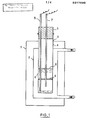
- FIG. 1 we see a vacuum envelope 1 surrounding a reservoir 2, in which a refrigerant is circulated continuously, as indicated by the arrows.
- a test tube 4 plunges into the refrigerant.
- the test tube 4 is closed by a plug 5 made of polytetrafluoroethylene which the rods of two thermo couples pass through electrical or Pt 100 temperature probes. These probes pass through a spacer 6, made of plastic, in particular polytetrafluoroethylene. The active part of the probe 7 plunges into the central, lower region of the liquid 9 in the test tube 4, while that of the probe 8 is located near the bottom and the external wall of the test tube.
- the casing 1 has a diameter of 80 mm and a height of 130 mm; the diameter of the tank 2 is 50 mm and the height of 100mm; the test tube 4 has a diameter of 30 mm for a height of 120 mm, a line indicating the level of the liquid is 50 mm above the bottom.
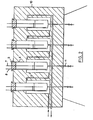
- Fig. 2 shows a body 10 filled with thermal insulation, in which are housed four reservoirs 2 of refrigerant, connected in series.
- a test tube 4 similar to that of FIG. 1 is immersed in each of the reservoirs, except that it is provided with a drain 11, making it possible to empty the test tube of its liquid, without removing it.
- There is thus a set of 4 work stations allowing a series of 4 cloud point and flow point determinations to be carried out simultaneously.
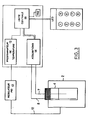
- FIG. 3 the main parts of a microprocessor connected to the device in FIG. 1 are briefly indicated. Since microprocessors are well known, there is no need to describe them in detail. It will only be noted that the programmer 1 controls the setpoint of the regulator 13 of the bath.
- the electrical signals from the temperature probes 7 and 8 are received in the acquisition circuit 14, to be processed in the central unit 16 to which the temperature programmer 15 is also connected.
- the operating mode of the use of the apparatus according to the invention includes the following manipulations.
- the liquid to be studied is preheated to a temperature of 20 ° or 25 ° C above the presumed cloud point, and it is then poured into the test tube up to the gauge line provided.
- the test tube 4 is then introduced into the cryogenic bath 2 and the probes 7 and 8 are placed as indicated in FIGS. 1 and 2.
- the microprocessor system is launched by pressing an appropriate key, which makes the device perform the following functions: control of the temperature of the cooling bath, test of probe 7 of the 1st station, acquisition of the temperatures on the four stations, treatment for the detection of cloud and flow points.
- a RESET key is used to restart a manipulation.
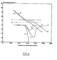
- the diagram in fig. 4 comprises a series of curves relating to the simultaneous determination of the cloud point and the pour point of a diesel, taken by way of example, using the automatic device described above.
- the abscissas show the numbers of scans carried out in the liquid of the test piece 4, during the constant cooling of 1 ° C per minute.
- the polls being carried out at equal time intervals, their number is equivalent to fixed durations.
- the temperatures acquired by the thermometric probes 7 and 8 are plotted on the ordinate.
- Line A represents the variations in temperature T 2 indicated by the probe 8, close to the wall of the test piece 4, as a function of time, i.e. T 2 ⁇ ( ).
- the very clear change in the slope of this curve A around 2850 scans, detects the crystallization of a component of the medium.
- the corresponding temperature i.e. the cloud point
- This indication fits with the horizontal line F which corresponds to the cloud point of the same diesel, determined in accordance with standards.
- Curve B shows the variations in temperature T 1 , acquired from the central probe 7, as a function of time, i.e. T 1 - ⁇ ( ). Its marked change of slope, around 3200 scans, corresponds to the pour point T 2 which is read on the probe 8 at the same time (same number of scans), that is to say for the same abscissa. Compared with the ordinate of line G, this temperature T 2 is in agreement with the value of the pour point found according to the standards (G).
- the first curvature, on each of these lines derivatives C and D indicates the appearance of a solid phase.
- the first curvature (on the left) much sharper than on curves A and B, that is to say the first change of slope on C, detects the cloud point, the value of which is given by a corresponding type B curve, at the same abscissa.
- the pour point is captured more clearly by the derivative curve D and evaluated on A.
- the curves C and D represent the derivatives of the filtered curves A and B and affected by an abscissa offset.
- the invention also preferably includes the drawing of a cumulative curve E, in order to avoid the detection of changes and parasitic phenomena which are not actually due to solidifications occurring within the liquid studied.
- This curve E constitutes the cumulation of the curve C with reset to zero each time the latter undergoes deviations between certain predetermined limits.
- the detection of the cloud point is only validated if the ordinate of the curve E exceeds a certain preset threshold.
- the pour point is detected after the cloud point has been determined.
Landscapes
- Chemical & Material Sciences (AREA)
- Health & Medical Sciences (AREA)
- Life Sciences & Earth Sciences (AREA)
- Biochemistry (AREA)
- Engineering & Computer Science (AREA)
- Pathology (AREA)
- Immunology (AREA)
- General Physics & Mathematics (AREA)
- General Health & Medical Sciences (AREA)
- Physics & Mathematics (AREA)
- Analytical Chemistry (AREA)
- Oil, Petroleum & Natural Gas (AREA)
- Medicinal Chemistry (AREA)
- Food Science & Technology (AREA)
- General Chemical & Material Sciences (AREA)
- Chemical Kinetics & Catalysis (AREA)
- Investigating Or Analyzing Materials Using Thermal Means (AREA)
- Investigating Or Analysing Materials By Optical Means (AREA)
Applications Claiming Priority (2)
| Application Number | Priority Date | Filing Date | Title |
|---|---|---|---|
| FR8512611 | 1985-08-22 | ||
| FR8512611A FR2586479B1 (fr) | 1985-08-22 | 1985-08-22 | Procede et application pour la determination des points de trouble et d'ecoulement |
Publications (2)
| Publication Number | Publication Date |
|---|---|
| EP0217690A2 true EP0217690A2 (de) | 1987-04-08 |
| EP0217690A3 EP0217690A3 (de) | 1990-01-17 |
Family
ID=9322337
Family Applications (1)
| Application Number | Title | Priority Date | Filing Date |
|---|---|---|---|
| EP86401806A Ceased EP0217690A3 (de) | 1985-08-22 | 1986-08-13 | Verfahren und Apparat zur Bestimmung des Trübungspunktes und des Stockpunktes |
Country Status (11)
| Country | Link |
|---|---|
| US (1) | US4770540A (de) |
| EP (1) | EP0217690A3 (de) |
| JP (1) | JPS6250651A (de) |
| BE (1) | BE905289A (de) |
| DE (1) | DE217690T1 (de) |
| DK (1) | DK399586A (de) |
| ES (1) | ES2001954A6 (de) |
| FI (1) | FI863388L (de) |
| FR (1) | FR2586479B1 (de) |
| IT (1) | IT1213327B (de) |
| NO (1) | NO863331L (de) |
Families Citing this family (15)
| Publication number | Priority date | Publication date | Assignee | Title |
|---|---|---|---|---|
| US6965815B1 (en) | 1987-05-27 | 2005-11-15 | Bilboa Instruments, Inc. | Spa control system |
| US5361215A (en) | 1987-05-27 | 1994-11-01 | Siege Industries, Inc. | Spa control system |
| FR2624973B1 (fr) * | 1987-12-17 | 1994-06-10 | Inst Francais Du Petrole | Dispositif de detection d'un phenomene thermique intervenant dans un produit |
| JPH0262948A (ja) * | 1988-08-30 | 1990-03-02 | Snow Brand Milk Prod Co Ltd | ゲル化点温度の測定方法 |
| JPH0747940B2 (ja) * | 1989-01-27 | 1995-05-24 | 日産自動車株式会社 | エンジンの回転制御装置 |
| US6604852B1 (en) * | 2000-12-09 | 2003-08-12 | Halliburton Energy Services, Inc. | High pressure brine crystallization point apparatus |
| ATE470005T1 (de) * | 2006-11-10 | 2010-06-15 | Johnson Diversey Inc | Sensorvorrichtung und verfahren |
| US8236168B2 (en) * | 2009-10-13 | 2012-08-07 | Exxonmobil Research And Engineering Company | Onset haze measurement apparatus and procedure |
| SE535889C2 (sv) * | 2011-06-09 | 2013-02-05 | Scania Cv Ab | Förfarande och system för att övervaka kvalitetsförsämringen hos olja |
| SE535957C2 (sv) * | 2011-06-09 | 2013-03-05 | Scania Cv Ab | Förfarande och system för att detektera paraffinering hos dieselbränsle i en bränsletank i ett motorfordon |
| RU2471186C1 (ru) * | 2011-09-30 | 2012-12-27 | Федеральное государственное бюджетное образовательное учреждение высшего профессионального образования "Ульяновская государственная сельскохозяйственная академия" | Устройство оперативного контроля качества биотоплива |
| CN107976464B (zh) * | 2016-10-25 | 2020-06-16 | 中国石油化工股份有限公司 | 监测航煤生产事故的方法及装置 |
| IT201900006482A1 (it) * | 2019-05-02 | 2020-11-02 | Chimec Spa | Dispositivo per la determinazione delle proprietà di fluidi idrocarburici e sostanze simili |
| RU2701373C1 (ru) * | 2019-06-13 | 2019-09-26 | Федеральное автономное учреждение "25 Государственный научно-исследовательский институт химмотологии Министерства обороны Российской Федерации" | Способ определения предельной температуры применения дизельных топлив |
| CN112903633A (zh) * | 2021-01-27 | 2021-06-04 | 哈尔滨职业技术学院 | 一种汽车油液低温检测方法 |
Family Cites Families (10)
| Publication number | Priority date | Publication date | Assignee | Title |
|---|---|---|---|---|
| US2672751A (en) * | 1951-09-24 | 1954-03-23 | Phillips Petroleum Co | Automatic time-temperature curve apparatus |
| GB1109269A (en) * | 1966-07-29 | 1968-04-10 | Mepag Ag | Determining the boiling points of liquids |
| US3643492A (en) * | 1970-04-21 | 1972-02-22 | Shell Oil Co | Pour and cloud point analyzer |
| US3667280A (en) * | 1970-07-15 | 1972-06-06 | Shell Oil Co | Method for determining the freezing point of a hydrocarbon |
| FR2131516A5 (de) * | 1971-03-30 | 1972-11-10 | Leybold Heraeus Verwaltung | |
| FR2391473A1 (fr) * | 1977-05-18 | 1978-12-15 | Electro Nite | Procede et dispositif pour la determination de la structure metallographique de metaux ou d'alliages |
| DE3004810A1 (de) * | 1980-02-09 | 1981-08-20 | Bayer Ag, 5090 Leverkusen | Vorrichtung fuer die differenzthermoanalyse |
| US4567849A (en) * | 1981-12-01 | 1986-02-04 | Texas Instruments Incorporated | Dipping liquid phase epitaxy for HgCdTe |
| NL8203013A (nl) * | 1982-07-28 | 1984-02-16 | Unie Van Kunstmestfab Bv | Werkwijze en inrichting voor het bepalen van de verzadigingstemperatuur van een oplossing. |
| FI66695C (fi) * | 1983-02-07 | 1984-11-12 | Aarre Matilainen | Foerfarande och apparat foer att maeta friktion i en plastekstruder |
-
1985
- 1985-08-22 FR FR8512611A patent/FR2586479B1/fr not_active Expired
-
1986
- 1986-08-13 EP EP86401806A patent/EP0217690A3/de not_active Ceased
- 1986-08-13 DE DE198686401806T patent/DE217690T1/de active Pending
- 1986-08-19 BE BE0/217055A patent/BE905289A/fr not_active IP Right Cessation
- 1986-08-19 NO NO863331A patent/NO863331L/no unknown
- 1986-08-19 JP JP61192222A patent/JPS6250651A/ja active Pending
- 1986-08-20 IT IT8621502A patent/IT1213327B/it active
- 1986-08-20 US US06/898,270 patent/US4770540A/en not_active Expired - Fee Related
- 1986-08-21 DK DK399586A patent/DK399586A/da not_active Application Discontinuation
- 1986-08-21 ES ES8601779A patent/ES2001954A6/es not_active Expired
- 1986-08-21 FI FI863388A patent/FI863388L/fi not_active Application Discontinuation
Also Published As
| Publication number | Publication date |
|---|---|
| FR2586479B1 (fr) | 1987-12-18 |
| DK399586D0 (da) | 1986-08-21 |
| US4770540A (en) | 1988-09-13 |
| FI863388A0 (fi) | 1986-08-21 |
| FR2586479A1 (fr) | 1987-02-27 |
| NO863331L (no) | 1987-02-23 |
| FI863388A7 (fi) | 1987-02-23 |
| IT8621502A0 (it) | 1986-08-20 |
| DK399586A (da) | 1987-02-23 |
| JPS6250651A (ja) | 1987-03-05 |
| BE905289A (fr) | 1987-02-19 |
| EP0217690A3 (de) | 1990-01-17 |
| IT1213327B (it) | 1989-12-20 |
| ES2001954A6 (es) | 1988-07-01 |
| DE217690T1 (de) | 1987-09-24 |
| NO863331D0 (no) | 1986-08-19 |
| FI863388L (fi) | 1987-02-23 |
Similar Documents
| Publication | Publication Date | Title |
|---|---|---|
| EP0217690A2 (de) | Verfahren und Apparat zur Bestimmung des Trübungspunktes und des Stockpunktes | |
| US4769215A (en) | Integrity preserving and determining urine sample collection apparatus | |
| US3559452A (en) | Thermal analysis of molten steel | |
| US6347884B1 (en) | Method and device for determining the stability of a water-hydrocarbon emulsion | |
| JP2003515123A (ja) | デュアル上昇管/シングル毛細管粘度計 | |
| US3667280A (en) | Method for determining the freezing point of a hydrocarbon | |
| EP0192551B1 (de) | Verfahren und Vorrichtung zur Bestimmung des Schmelzpunkts von Karbureaktoren | |
| US3173288A (en) | Melting point tester | |
| EP3541512B1 (de) | Vorrichtung zur überwachung einer biologischen probe, insbesondere in der vorbereitung zur analyse in einem labor | |
| EP0240432B1 (de) | Verfahren und Vorrichtung zur Untersuchung der Eigenschaften einer Bierschaumschicht in Abhängigkeit von der Zeit | |
| WO1995031704A1 (fr) | Dispositif autonome de controle de temperatures limites lors du transport des denrees perissables | |
| EP1194772B1 (de) | Verfahren und vorrichtung zum zählen von einschlüssen in einer in einem gefäss befindlichen metallschmelze mittels ultraschall | |
| Barella et al. | Unlocking the potential of melting calorimetry: a field protocol for liquid water content measurement in snow | |
| US2564892A (en) | Viscosimeter | |
| JP4242989B2 (ja) | 針入度またはちょう度試験器および試験方法 | |
| FR2692988A1 (fr) | Procédé et dispositif de détermination de la limite de fatigue d'un matériau. | |
| EP0533562B1 (de) | Vorrichtung zum Nachweis des Auftretens oder Verschwindens zweier Phasen in einer flüssigen Kohlenwasserstoff-Substanz | |
| FR2858056A1 (fr) | Dispositif et procede de mesure de la quantite d'air dans une huile hydraulique | |
| CN104931387A (zh) | 手持式数字密度计 | |
| CN114813437B (zh) | 用于检测现场油砂清蜡效果的装置 | |
| US2823541A (en) | Viscosity comparator | |
| JPH01229950A (ja) | 相変化の臨界値測定方法及びその装置 | |
| Reddy | Use of Mango Seed Bio-Diesel as a Diesel Fuel Extender for a 4-Stroke CI Engine | |
| US2997881A (en) | Apparatus and method for determining specific gravity | |
| DE694013C (de) | Verfahren zur Feststellung der Guete (Luftleere) von Thermosgefaessen und Vorrichtung hierzu |
Legal Events
| Date | Code | Title | Description |
|---|---|---|---|
| PUAI | Public reference made under article 153(3) epc to a published international application that has entered the european phase |
Free format text: ORIGINAL CODE: 0009012 |
|
| AK | Designated contracting states |
Kind code of ref document: A2 Designated state(s): AT DE GB NL SE |
|
| TCAT | At: translation of patent claims filed | ||
| 17P | Request for examination filed |
Effective date: 19870408 |
|
| TCNL | Nl: translation of patent claims filed | ||
| DET | De: translation of patent claims | ||
| PUAL | Search report despatched |
Free format text: ORIGINAL CODE: 0009013 |
|
| AK | Designated contracting states |
Kind code of ref document: A3 Designated state(s): AT DE GB NL SE |
|
| 17Q | First examination report despatched |
Effective date: 19910912 |
|
| RTI1 | Title (correction) | ||
| STAA | Information on the status of an ep patent application or granted ep patent |
Free format text: STATUS: THE APPLICATION HAS BEEN REFUSED |
|
| 18R | Application refused |
Effective date: 19920927 |
|
| RIN1 | Information on inventor provided before grant (corrected) |
Inventor name: CHAGUE, BENOIT Inventor name: JULLIAT, PHILIPPE Inventor name: ESSON, SERGE |