EP0217536A1 - Rouleau de séchage - Google Patents
Rouleau de séchage Download PDFInfo
- Publication number
- EP0217536A1 EP0217536A1 EP86306600A EP86306600A EP0217536A1 EP 0217536 A1 EP0217536 A1 EP 0217536A1 EP 86306600 A EP86306600 A EP 86306600A EP 86306600 A EP86306600 A EP 86306600A EP 0217536 A1 EP0217536 A1 EP 0217536A1
- Authority
- EP
- European Patent Office
- Prior art keywords
- roll
- location
- chamber
- condensate
- vapor
- Prior art date
- Legal status (The legal status is an assumption and is not a legal conclusion. Google has not performed a legal analysis and makes no representation as to the accuracy of the status listed.)
- Granted
Links
- 238000010438 heat treatment Methods 0.000 claims abstract description 6
- 239000000463 material Substances 0.000 claims abstract description 6
- 238000002347 injection Methods 0.000 claims 3
- 239000007924 injection Substances 0.000 claims 3
- 238000001035 drying Methods 0.000 description 13
- 238000000034 method Methods 0.000 description 5
- 238000010793 Steam injection (oil industry) Methods 0.000 description 3
- 238000009833 condensation Methods 0.000 description 2
- 230000005494 condensation Effects 0.000 description 2
- 238000004519 manufacturing process Methods 0.000 description 2
- 230000000994 depressogenic effect Effects 0.000 description 1
- 238000010981 drying operation Methods 0.000 description 1
- 230000004907 flux Effects 0.000 description 1
- 238000005406 washing Methods 0.000 description 1
Images

Classifications
-
- F—MECHANICAL ENGINEERING; LIGHTING; HEATING; WEAPONS; BLASTING
- F26—DRYING
- F26B—DRYING SOLID MATERIALS OR OBJECTS BY REMOVING LIQUID THEREFROM
- F26B13/00—Machines and apparatus for drying fabrics, fibres, yarns, or other materials in long lengths, with progressive movement
- F26B13/10—Arrangements for feeding, heating or supporting materials; Controlling movement, tension or position of materials
- F26B13/14—Rollers, drums, cylinders; Arrangement of drives, supports, bearings, cleaning
- F26B13/18—Rollers, drums, cylinders; Arrangement of drives, supports, bearings, cleaning heated or cooled, e.g. from inside, the material being dried on the outside surface by conduction
- F26B13/183—Arrangements for heating, cooling, condensate removal
-
- D—TEXTILES; PAPER
- D21—PAPER-MAKING; PRODUCTION OF CELLULOSE
- D21F—PAPER-MAKING MACHINES; METHODS OF PRODUCING PAPER THEREON
- D21F5/00—Dryer section of machines for making continuous webs of paper
- D21F5/02—Drying on cylinders
- D21F5/022—Heating the cylinders
- D21F5/028—Heating the cylinders using steam
-
- F—MECHANICAL ENGINEERING; LIGHTING; HEATING; WEAPONS; BLASTING
- F26—DRYING
- F26B—DRYING SOLID MATERIALS OR OBJECTS BY REMOVING LIQUID THEREFROM
- F26B25/00—Details of general application not covered by group F26B21/00 or F26B23/00
- F26B25/20—Rollers
-
- F—MECHANICAL ENGINEERING; LIGHTING; HEATING; WEAPONS; BLASTING
- F28—HEAT EXCHANGE IN GENERAL
- F28F—DETAILS OF HEAT-EXCHANGE AND HEAT-TRANSFER APPARATUS, OF GENERAL APPLICATION
- F28F13/00—Arrangements for modifying heat-transfer, e.g. increasing, decreasing
- F28F13/06—Arrangements for modifying heat-transfer, e.g. increasing, decreasing by affecting the pattern of flow of the heat-exchange media
- F28F13/08—Arrangements for modifying heat-transfer, e.g. increasing, decreasing by affecting the pattern of flow of the heat-exchange media by varying the cross-section of the flow channels
-
- F—MECHANICAL ENGINEERING; LIGHTING; HEATING; WEAPONS; BLASTING
- F28—HEAT EXCHANGE IN GENERAL
- F28F—DETAILS OF HEAT-EXCHANGE AND HEAT-TRANSFER APPARATUS, OF GENERAL APPLICATION
- F28F5/00—Elements specially adapted for movement
- F28F5/02—Rotary drums or rollers
-
- F—MECHANICAL ENGINEERING; LIGHTING; HEATING; WEAPONS; BLASTING
- F28—HEAT EXCHANGE IN GENERAL
- F28D—HEAT-EXCHANGE APPARATUS, NOT PROVIDED FOR IN ANOTHER SUBCLASS, IN WHICH THE HEAT-EXCHANGE MEDIA DO NOT COME INTO DIRECT CONTACT
- F28D21/00—Heat-exchange apparatus not covered by any of the groups F28D1/00 - F28D20/00
- F28D2021/0019—Other heat exchangers for particular applications; Heat exchange systems not otherwise provided for
- F28D2021/0061—Other heat exchangers for particular applications; Heat exchange systems not otherwise provided for for phase-change applications
- F28D2021/0063—Condensers
Definitions
- This invention relates to vapor-heated rolls for drying or heating material passing thereover, and more particularly, it relates to vapor-heated rolls for handling variable drying loads along their length.
- Rapidly rotating heated rolls are extensively used in continuous drying operations.
- Typical drying applications such as found in the paper industry require a uniform heat transfer or heat flux rate at each point along the cylindrical surface of the roll.
- paper webs pass in a serpentine path over a series of rolls.
- the rate of condensate generation at each point along the axis of the roll is uniform.
- the drying roll of this invention provides increased drying capacity under the variable drying loads along the roll axis, both by managing condensate movement inside the roll heating chamber and by selecting the location from which condensate is removed from the heating chamber.
- the roll comprises first and second concentric cylindrical walls spaced from each other and sealed at each end by plates to provide a chamber within the roll.
- the inner surface of the outer wall is tapered from each end of the roll to a specified location to provide a chamber that has a gradually increasing cross-sectional area from each end of the roll to said specified location.
- the supporting shaft has two concentric passages, one for steam and one for condensate.
- a condensate removal pipe is provided which, at one end, passes through the second wall into the chamber at said specified location and, at its other end. communicates with the condensate-removal passage of the supporting shaft.
- a steam-injection pipe is provided which, at one end, communicates with the chamber at a position remote from said specified location and, at its other end, communicates with the steam injection-passage of the supporting shaft.
- the steam-injection pipe enters the chamber very close to the yarn exit end of the roll. More preferably, there are two condensate-removal pipes angularly spaced 180 degrees apart, and one steam-injection pipe angularly spaced midway between the two condensate-removal pipes.
- the distance of said specified location from the end of the roll that the yarn enters upon is from about 20 to 40 percent of the total length of the roll. preferably the distance is about 30 percent.
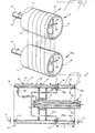
- the embodiment chosen for purposes of illustration includes a water-laden multifilament threadline 10 advancing from a source (not shown) to a pair of rotatably driven vapor-heated rolls 12, 12a.
- the rolls 12, 12a are substantially identical except that the longitudinal axis of 12a is skewed with respect to 12 to allow the threadline to spirally advance from the threadline entrance A at one end of the roll 12 to the threadline exit B at the other end of roll 12.
- the roll 12 comprises first and second concentric cylindrical walls 11, 13, respectively, spaced from each other and sealed at each end by annular end plates 16, 16a to define an annular chamber 15 within the roll 12.
- the outer surface 17 of wall 11 constitutes the working surface of the roll and the location C.
- the angle of taper of wall 11 from the threadline entrance of the roll is designated 8 and the angle of taper from the threadline exit of the roll is designated 9.
- a rotatably driven support shaft 14 is attached in axial alignment with the roll to the inner wall 13 of the roll by means of bracket 18.
- the support shaft has concentric passages 14a, 14b passing therethrough.
- a pair of condensate removal nozzles 22, 22a are in communication with the passage 14a of shaft 14 via pipes 24, 24a, respectively.
- the nozzles 22, 22a are threaded through wall 13 for adjustability toward and away from surface 19 and located directly opposite each other, i.e., 180 degrees apart in chamber 15 adjacent location C.
- Optimum operation requires precise setting of the gap between nozzles 22. 22a and surface 19. If the gap is too small, rapid enough removal of condensate becomes impossible. If, on the other hand, it is too large, build-up of condensate will also occur. Gaps of about 1.8 mm are preferred.
- Wall surface 19 is flattened about position C enough that a uniform gap exists between the tips of nozzles 22, 22a and surface 19.
- Curve E shows the improved temperature profile of the roll surface using the roll of this invention, from which it can be seen that surface temperature is much closer to the temperature of the feed steam at every point along the surface. Regardless of the drying system involved, the distinct improvement of this invention will be obtained when the minimum wall-thickness and siphon(s) are within 20 to 40s of the roll length, measured from the threadline entrance on the roll.
- taper angles are not critical. The bigger the angle, the thicker must be the wall to accommodate it. On the other hand, best drainage action occurs when at least 0.5 degree of taper is employed. In a preferred embodiment, the taper angles 8, 9 are about 2 degrees and about 1 degree, respectively.
Landscapes
- Engineering & Computer Science (AREA)
- Mechanical Engineering (AREA)
- General Engineering & Computer Science (AREA)
- Physics & Mathematics (AREA)
- Thermal Sciences (AREA)
- Textile Engineering (AREA)
- Drying Of Solid Materials (AREA)
Applications Claiming Priority (2)
| Application Number | Priority Date | Filing Date | Title |
|---|---|---|---|
| US770346 | 1985-08-28 | ||
| US06/770,346 US4644668A (en) | 1985-08-28 | 1985-08-28 | Dryer roll |
Publications (2)
| Publication Number | Publication Date |
|---|---|
| EP0217536A1 true EP0217536A1 (fr) | 1987-04-08 |
| EP0217536B1 EP0217536B1 (fr) | 1988-11-02 |
Family
ID=25088250
Family Applications (1)
| Application Number | Title | Priority Date | Filing Date |
|---|---|---|---|
| EP86306600A Expired EP0217536B1 (fr) | 1985-08-28 | 1986-08-27 | Rouleau de séchage |
Country Status (6)
| Country | Link |
|---|---|
| US (1) | US4644668A (fr) |
| EP (1) | EP0217536B1 (fr) |
| JP (1) | JPS6259385A (fr) |
| KR (1) | KR910006872B1 (fr) |
| CA (1) | CA1291641C (fr) |
| DE (1) | DE3661109D1 (fr) |
Families Citing this family (6)
| Publication number | Priority date | Publication date | Assignee | Title |
|---|---|---|---|---|
| US4821427A (en) * | 1988-04-18 | 1989-04-18 | E. I. Du Pont De Nemours And Company | Method and apparatus for reducing the moisture content of wet yarns |
| FR2744628B1 (fr) * | 1996-02-08 | 1998-04-17 | Deckner Andre Georges | Tige d'ancrage de prothese |
| US5899264A (en) * | 1997-09-17 | 1999-05-04 | Marquip, Inc. | Steam supply and condensate removal apparatus for heated roll |
| US6877246B1 (en) * | 2003-12-30 | 2005-04-12 | Kimberly-Clark Worldwide, Inc. | Through-air dryer assembly |
| CN1322297C (zh) * | 2004-03-29 | 2007-06-20 | 张善智 | 常压高温节能烘干辊筒机组 |
| CN118854472B (zh) * | 2024-09-25 | 2024-11-29 | 洛阳德锐环保科技有限公司 | 一种再生涤纶短纤维烘干定型装置 |
Citations (7)
| Publication number | Priority date | Publication date | Assignee | Title |
|---|---|---|---|---|
| DE112852C (fr) * | ||||
| US2697284A (en) * | 1950-09-01 | 1954-12-21 | Lukens Steel Co | Double shell drier roll construction |
| US2789368A (en) * | 1952-11-15 | 1957-04-23 | American Cyanamid Co | Apparatus for processing a thread |
| FR1383468A (fr) * | 1964-02-25 | 1964-12-24 | Leesona Holt Ltd | Cylindre de séchage perfectionné |
| US3242583A (en) * | 1963-11-06 | 1966-03-29 | Johnson Corp | Method of drying a running web of sheet material |
| DE1801543A1 (de) * | 1968-10-05 | 1970-05-21 | Escher Wyss Gmbh | Dampfbeheizter Trockenzylinder |
| CH492184A (de) * | 1969-01-08 | 1970-06-15 | Barmag Barmer Maschf | Dampfbeheizte umlaufende Walze |
Family Cites Families (9)
| Publication number | Priority date | Publication date | Assignee | Title |
|---|---|---|---|---|
| US1575249A (en) * | 1923-12-15 | 1926-03-02 | Beloit Iron Works | Apparatus for removing condensate from revolving driers |
| US2486719A (en) * | 1946-03-16 | 1949-11-01 | Messinger William | Drier |
| US2643099A (en) * | 1950-11-04 | 1953-06-23 | Du Pont | Vapor heated roll |
| US2933825A (en) * | 1956-11-19 | 1960-04-26 | Paper Converting Machine Co | Moisture removal system |
| US3169050A (en) * | 1961-01-25 | 1965-02-09 | Scott Paper Co | Rotary cylinder drying drum with stress relieving expansion means |
| DE1222434B (de) * | 1964-08-13 | 1966-08-04 | Agfa Gevaert Ag | Mit Fluessigkeitsumlauf temperierte Walze |
| US3302698A (en) * | 1964-12-16 | 1967-02-07 | Du Pont | Heat exchange apparatus |
| US3619539A (en) * | 1970-05-22 | 1971-11-09 | Honeywell Inc | Fluid heated roll |
| DE3148948C2 (de) * | 1981-12-10 | 1983-12-15 | J.M. Voith Gmbh, 7920 Heidenheim | Einrichtung zum Abführen von Kondensat aus einem dampfbeheizten, drehbaren Trocknungszylinder |
-
1985
- 1985-08-28 US US06/770,346 patent/US4644668A/en not_active Expired - Lifetime
-
1986
- 1986-08-21 CA CA000516531A patent/CA1291641C/fr not_active Expired - Lifetime
- 1986-08-25 JP JP61197465A patent/JPS6259385A/ja active Pending
- 1986-08-27 EP EP86306600A patent/EP0217536B1/fr not_active Expired
- 1986-08-27 DE DE8686306600T patent/DE3661109D1/de not_active Expired
- 1986-08-27 KR KR1019860007108A patent/KR910006872B1/ko not_active Expired
Patent Citations (7)
| Publication number | Priority date | Publication date | Assignee | Title |
|---|---|---|---|---|
| DE112852C (fr) * | ||||
| US2697284A (en) * | 1950-09-01 | 1954-12-21 | Lukens Steel Co | Double shell drier roll construction |
| US2789368A (en) * | 1952-11-15 | 1957-04-23 | American Cyanamid Co | Apparatus for processing a thread |
| US3242583A (en) * | 1963-11-06 | 1966-03-29 | Johnson Corp | Method of drying a running web of sheet material |
| FR1383468A (fr) * | 1964-02-25 | 1964-12-24 | Leesona Holt Ltd | Cylindre de séchage perfectionné |
| DE1801543A1 (de) * | 1968-10-05 | 1970-05-21 | Escher Wyss Gmbh | Dampfbeheizter Trockenzylinder |
| CH492184A (de) * | 1969-01-08 | 1970-06-15 | Barmag Barmer Maschf | Dampfbeheizte umlaufende Walze |
Also Published As
| Publication number | Publication date |
|---|---|
| US4644668A (en) | 1987-02-24 |
| EP0217536B1 (fr) | 1988-11-02 |
| KR910006872B1 (ko) | 1991-09-09 |
| DE3661109D1 (en) | 1988-12-08 |
| JPS6259385A (ja) | 1987-03-16 |
| KR870002432A (ko) | 1987-03-31 |
| CA1291641C (fr) | 1991-11-05 |
Similar Documents
| Publication | Publication Date | Title |
|---|---|---|
| FI92942C (fi) | Puristinlaite | |
| US4786529A (en) | Cross directional gloss controller | |
| EP0217536B1 (fr) | Rouleau de séchage | |
| US4158128A (en) | Roller for applying uniform load across the width of processed sheet material | |
| CA1104817A (fr) | Sechoir de papier en bande | |
| US4118843A (en) | Processes and apparatus for thermal treatment of filaments | |
| KR100365804B1 (ko) | 합성다섬조사제조를위한방법및장치 | |
| FI90675B (fi) | Tela ja hihna -tyyppiä oleva puristin | |
| US4485567A (en) | Dryer felt run | |
| FI60133C (fi) | Foerfarande foer industning av vattenhaltiga vaetskor | |
| CN100404738C (zh) | 在卷曲变形机中用来加热长丝的接触式加热装置 | |
| US4135280A (en) | Method and apparatus for texturizing continuous filaments | |
| EP0338226B1 (fr) | Procédé et dispositif pour réduire le degré d'humidité des fils mouillés | |
| US3496647A (en) | Dryer for fabrics and the like | |
| JPS6120656B2 (fr) | ||
| KR20000069390A (ko) | 섬유 웹 건조 방법 및 장치 | |
| CN110820059B (zh) | 导丝辊 | |
| EP0617151B1 (fr) | Méthode de maintien en pression d'une machine à traitement thermique en continu de cables en fibre synthétique | |
| US3555639A (en) | Yarn heating tube and method | |
| JP3430244B2 (ja) | 走行する糸のための加熱部材 | |
| SU1285097A1 (ru) | Устройство дл сушки рулонных материалов | |
| FI87668C (fi) | Foerfarande och anordning foer behandling av en banformig produkt | |
| US3786574A (en) | Method for removing water from tow | |
| CA1161223A (fr) | Methode et dispositif de fabrication de filaments crepes continus | |
| EP1780331A1 (fr) | Ensemble de séchage |
Legal Events
| Date | Code | Title | Description |
|---|---|---|---|
| PUAI | Public reference made under article 153(3) epc to a published international application that has entered the european phase |
Free format text: ORIGINAL CODE: 0009012 |
|
| AK | Designated contracting states |
Kind code of ref document: A1 Designated state(s): DE FR GB NL |
|
| 17P | Request for examination filed |
Effective date: 19870912 |
|
| 17Q | First examination report despatched |
Effective date: 19880226 |
|
| GRAA | (expected) grant |
Free format text: ORIGINAL CODE: 0009210 |
|
| AK | Designated contracting states |
Kind code of ref document: B1 Designated state(s): DE FR GB NL |
|
| REF | Corresponds to: |
Ref document number: 3661109 Country of ref document: DE Date of ref document: 19881208 |
|
| ET | Fr: translation filed | ||
| PLBE | No opposition filed within time limit |
Free format text: ORIGINAL CODE: 0009261 |
|
| STAA | Information on the status of an ep patent application or granted ep patent |
Free format text: STATUS: NO OPPOSITION FILED WITHIN TIME LIMIT |
|
| 26N | No opposition filed | ||
| PGFP | Annual fee paid to national office [announced via postgrant information from national office to epo] |
Ref country code: FR Payment date: 19940601 Year of fee payment: 9 |
|
| PGFP | Annual fee paid to national office [announced via postgrant information from national office to epo] |
Ref country code: DE Payment date: 19940621 Year of fee payment: 9 |
|
| PGFP | Annual fee paid to national office [announced via postgrant information from national office to epo] |
Ref country code: GB Payment date: 19940623 Year of fee payment: 9 |
|
| PGFP | Annual fee paid to national office [announced via postgrant information from national office to epo] |
Ref country code: NL Payment date: 19940831 Year of fee payment: 9 |
|
| PG25 | Lapsed in a contracting state [announced via postgrant information from national office to epo] |
Ref country code: GB Effective date: 19950827 |
|
| PG25 | Lapsed in a contracting state [announced via postgrant information from national office to epo] |
Ref country code: NL Effective date: 19960301 |
|
| GBPC | Gb: european patent ceased through non-payment of renewal fee |
Effective date: 19950827 |
|
| PG25 | Lapsed in a contracting state [announced via postgrant information from national office to epo] |
Ref country code: FR Effective date: 19960430 |
|
| NLV4 | Nl: lapsed or anulled due to non-payment of the annual fee |
Effective date: 19960301 |
|
| PG25 | Lapsed in a contracting state [announced via postgrant information from national office to epo] |
Ref country code: DE Effective date: 19960501 |
|
| REG | Reference to a national code |
Ref country code: FR Ref legal event code: ST |