EP0217536A1 - Dryer roll - Google Patents
Dryer roll Download PDFInfo
- Publication number
- EP0217536A1 EP0217536A1 EP86306600A EP86306600A EP0217536A1 EP 0217536 A1 EP0217536 A1 EP 0217536A1 EP 86306600 A EP86306600 A EP 86306600A EP 86306600 A EP86306600 A EP 86306600A EP 0217536 A1 EP0217536 A1 EP 0217536A1
- Authority
- EP
- European Patent Office
- Prior art keywords
- roll
- location
- chamber
- condensate
- vapor
- Prior art date
- Legal status (The legal status is an assumption and is not a legal conclusion. Google has not performed a legal analysis and makes no representation as to the accuracy of the status listed.)
- Granted
Links
- 238000010438 heat treatment Methods 0.000 claims abstract description 6
- 239000000463 material Substances 0.000 claims abstract description 6
- 238000002347 injection Methods 0.000 claims 3
- 239000007924 injection Substances 0.000 claims 3
- 238000001035 drying Methods 0.000 description 13
- 238000000034 method Methods 0.000 description 5
- 238000010793 Steam injection (oil industry) Methods 0.000 description 3
- 238000009833 condensation Methods 0.000 description 2
- 230000005494 condensation Effects 0.000 description 2
- 238000004519 manufacturing process Methods 0.000 description 2
- 230000000994 depressogenic effect Effects 0.000 description 1
- 238000010981 drying operation Methods 0.000 description 1
- 230000004907 flux Effects 0.000 description 1
- 238000005406 washing Methods 0.000 description 1
Images

Classifications
-
- F—MECHANICAL ENGINEERING; LIGHTING; HEATING; WEAPONS; BLASTING
- F26—DRYING
- F26B—DRYING SOLID MATERIALS OR OBJECTS BY REMOVING LIQUID THEREFROM
- F26B13/00—Machines and apparatus for drying fabrics, fibres, yarns, or other materials in long lengths, with progressive movement
- F26B13/10—Arrangements for feeding, heating or supporting materials; Controlling movement, tension or position of materials
- F26B13/14—Rollers, drums, cylinders; Arrangement of drives, supports, bearings, cleaning
- F26B13/18—Rollers, drums, cylinders; Arrangement of drives, supports, bearings, cleaning heated or cooled, e.g. from inside, the material being dried on the outside surface by conduction
- F26B13/183—Arrangements for heating, cooling, condensate removal
-
- D—TEXTILES; PAPER
- D21—PAPER-MAKING; PRODUCTION OF CELLULOSE
- D21F—PAPER-MAKING MACHINES; METHODS OF PRODUCING PAPER THEREON
- D21F5/00—Dryer section of machines for making continuous webs of paper
- D21F5/02—Drying on cylinders
- D21F5/022—Heating the cylinders
- D21F5/028—Heating the cylinders using steam
-
- F—MECHANICAL ENGINEERING; LIGHTING; HEATING; WEAPONS; BLASTING
- F26—DRYING
- F26B—DRYING SOLID MATERIALS OR OBJECTS BY REMOVING LIQUID THEREFROM
- F26B25/00—Details of general application not covered by group F26B21/00 or F26B23/00
- F26B25/20—Rollers
-
- F—MECHANICAL ENGINEERING; LIGHTING; HEATING; WEAPONS; BLASTING
- F28—HEAT EXCHANGE IN GENERAL
- F28F—DETAILS OF HEAT-EXCHANGE AND HEAT-TRANSFER APPARATUS, OF GENERAL APPLICATION
- F28F13/00—Arrangements for modifying heat-transfer, e.g. increasing, decreasing
- F28F13/06—Arrangements for modifying heat-transfer, e.g. increasing, decreasing by affecting the pattern of flow of the heat-exchange media
- F28F13/08—Arrangements for modifying heat-transfer, e.g. increasing, decreasing by affecting the pattern of flow of the heat-exchange media by varying the cross-section of the flow channels
-
- F—MECHANICAL ENGINEERING; LIGHTING; HEATING; WEAPONS; BLASTING
- F28—HEAT EXCHANGE IN GENERAL
- F28F—DETAILS OF HEAT-EXCHANGE AND HEAT-TRANSFER APPARATUS, OF GENERAL APPLICATION
- F28F5/00—Elements specially adapted for movement
- F28F5/02—Rotary drums or rollers
-
- F—MECHANICAL ENGINEERING; LIGHTING; HEATING; WEAPONS; BLASTING
- F28—HEAT EXCHANGE IN GENERAL
- F28D—HEAT-EXCHANGE APPARATUS, NOT PROVIDED FOR IN ANOTHER SUBCLASS, IN WHICH THE HEAT-EXCHANGE MEDIA DO NOT COME INTO DIRECT CONTACT
- F28D21/00—Heat-exchange apparatus not covered by any of the groups F28D1/00 - F28D20/00
- F28D2021/0019—Other heat exchangers for particular applications; Heat exchange systems not otherwise provided for
- F28D2021/0061—Other heat exchangers for particular applications; Heat exchange systems not otherwise provided for for phase-change applications
- F28D2021/0063—Condensers
Definitions
- This invention relates to vapor-heated rolls for drying or heating material passing thereover, and more particularly, it relates to vapor-heated rolls for handling variable drying loads along their length.
- Rapidly rotating heated rolls are extensively used in continuous drying operations.
- Typical drying applications such as found in the paper industry require a uniform heat transfer or heat flux rate at each point along the cylindrical surface of the roll.
- paper webs pass in a serpentine path over a series of rolls.
- the rate of condensate generation at each point along the axis of the roll is uniform.
- the drying roll of this invention provides increased drying capacity under the variable drying loads along the roll axis, both by managing condensate movement inside the roll heating chamber and by selecting the location from which condensate is removed from the heating chamber.
- the roll comprises first and second concentric cylindrical walls spaced from each other and sealed at each end by plates to provide a chamber within the roll.
- the inner surface of the outer wall is tapered from each end of the roll to a specified location to provide a chamber that has a gradually increasing cross-sectional area from each end of the roll to said specified location.
- the supporting shaft has two concentric passages, one for steam and one for condensate.
- a condensate removal pipe is provided which, at one end, passes through the second wall into the chamber at said specified location and, at its other end. communicates with the condensate-removal passage of the supporting shaft.
- a steam-injection pipe is provided which, at one end, communicates with the chamber at a position remote from said specified location and, at its other end, communicates with the steam injection-passage of the supporting shaft.
- the steam-injection pipe enters the chamber very close to the yarn exit end of the roll. More preferably, there are two condensate-removal pipes angularly spaced 180 degrees apart, and one steam-injection pipe angularly spaced midway between the two condensate-removal pipes.
- the distance of said specified location from the end of the roll that the yarn enters upon is from about 20 to 40 percent of the total length of the roll. preferably the distance is about 30 percent.
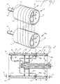
- the embodiment chosen for purposes of illustration includes a water-laden multifilament threadline 10 advancing from a source (not shown) to a pair of rotatably driven vapor-heated rolls 12, 12a.
- the rolls 12, 12a are substantially identical except that the longitudinal axis of 12a is skewed with respect to 12 to allow the threadline to spirally advance from the threadline entrance A at one end of the roll 12 to the threadline exit B at the other end of roll 12.
- the roll 12 comprises first and second concentric cylindrical walls 11, 13, respectively, spaced from each other and sealed at each end by annular end plates 16, 16a to define an annular chamber 15 within the roll 12.
- the outer surface 17 of wall 11 constitutes the working surface of the roll and the location C.
- the angle of taper of wall 11 from the threadline entrance of the roll is designated 8 and the angle of taper from the threadline exit of the roll is designated 9.
- a rotatably driven support shaft 14 is attached in axial alignment with the roll to the inner wall 13 of the roll by means of bracket 18.
- the support shaft has concentric passages 14a, 14b passing therethrough.
- a pair of condensate removal nozzles 22, 22a are in communication with the passage 14a of shaft 14 via pipes 24, 24a, respectively.
- the nozzles 22, 22a are threaded through wall 13 for adjustability toward and away from surface 19 and located directly opposite each other, i.e., 180 degrees apart in chamber 15 adjacent location C.
- Optimum operation requires precise setting of the gap between nozzles 22. 22a and surface 19. If the gap is too small, rapid enough removal of condensate becomes impossible. If, on the other hand, it is too large, build-up of condensate will also occur. Gaps of about 1.8 mm are preferred.
- Wall surface 19 is flattened about position C enough that a uniform gap exists between the tips of nozzles 22, 22a and surface 19.
- Curve E shows the improved temperature profile of the roll surface using the roll of this invention, from which it can be seen that surface temperature is much closer to the temperature of the feed steam at every point along the surface. Regardless of the drying system involved, the distinct improvement of this invention will be obtained when the minimum wall-thickness and siphon(s) are within 20 to 40s of the roll length, measured from the threadline entrance on the roll.
- taper angles are not critical. The bigger the angle, the thicker must be the wall to accommodate it. On the other hand, best drainage action occurs when at least 0.5 degree of taper is employed. In a preferred embodiment, the taper angles 8, 9 are about 2 degrees and about 1 degree, respectively.
Landscapes
- Engineering & Computer Science (AREA)
- Mechanical Engineering (AREA)
- General Engineering & Computer Science (AREA)
- Physics & Mathematics (AREA)
- Thermal Sciences (AREA)
- Textile Engineering (AREA)
- Drying Of Solid Materials (AREA)
Abstract
Description
- This invention relates to vapor-heated rolls for drying or heating material passing thereover, and more particularly, it relates to vapor-heated rolls for handling variable drying loads along their length.
- Rapidly rotating heated rolls are extensively used in continuous drying operations. Typical drying applications such as found in the paper industry require a uniform heat transfer or heat flux rate at each point along the cylindrical surface of the roll. In these processes, paper webs pass in a serpentine path over a series of rolls. In the case of rolls heated by condensation of vapor, such as steam, the rate of condensate generation at each point along the axis of the roll is uniform.
- Other industrial drying processes treat webs or individual threadlines comprised of multiple filaments by laying the web or filaments onto one end of a drying roll and spirally advancing the product along the roll until it is removed from the opposite end of the roll to pass to the next treatment step in the process. In the manufacture of wet-spun yarns or those requiring aqueous washing or extracting before windup, a drying step is utilized wherein product enters upon a drying roll at a high moisture level and is progressively dried to the desired moisture level as it advances along the longitudinal axis of the roll. Conditions in the roll interior. where condensation is occurring, are different from those encountered in rolls used to dry paper. The heat transfer rate varies as the product is dried and therefore the rate of condensate generation varies. This requires a different method of managing condensate removal from the roll to compensate for the variable thickness of condensate which collects on the interior surface of the outside wall. The thicker the condensate layer, the lower is the heat transfer rate. Greatest heat transfer rate occurs close to the roll-end where yarn enters, and condensate build-up here severely reduces both the drying rate and production capacity. In the past, processes have depended on increased pressure difference between the supply and discharge sides of the roll heating chamber to convey condensate from the roll. This results in wasted steam since excess steam is required to convey condensate from the roll. This conveying steam is therefore unavailable to condense and provide energy for product drying. Prior methods of condensate removal did not minimize thickness of the film of condensate and therefore limited the rate at which product could be dried.
- The drying roll of this invention provides increased drying capacity under the variable drying loads along the roll axis, both by managing condensate movement inside the roll heating chamber and by selecting the location from which condensate is removed from the heating chamber.
- The roll comprises first and second concentric cylindrical walls spaced from each other and sealed at each end by plates to provide a chamber within the roll. The inner surface of the outer wall is tapered from each end of the roll to a specified location to provide a chamber that has a gradually increasing cross-sectional area from each end of the roll to said specified location. There is a rotatable supporting shaft attached to the inner wall of the roll. The supporting shaft has two concentric passages, one for steam and one for condensate. A condensate removal pipe is provided which, at one end, passes through the second wall into the chamber at said specified location and, at its other end. communicates with the condensate-removal passage of the supporting shaft. Likewise, a steam-injection pipe is provided which, at one end, communicates with the chamber at a position remote from said specified location and, at its other end, communicates with the steam injection-passage of the supporting shaft. Preferably, the steam-injection pipe enters the chamber very close to the yarn exit end of the roll. More preferably, there are two condensate-removal pipes angularly spaced 180 degrees apart, and one steam-injection pipe angularly spaced midway between the two condensate-removal pipes. The distance of said specified location from the end of the roll that the yarn enters upon is from about 20 to 40 percent of the total length of the roll. preferably the distance is about 30 percent.
-
- Fig. 1 is a schematic representation of a yarn passing around two driven vapor-heated rolls of the invention.
- Fig. 2 is a side elevation view partially in section of one of the rolls in Fig. 1.
- Fig. 3 is a graph of temperature profile along the length of the vapor heated roll of this invention as compared to a temperature profile of a prior art vapor heated roll.
- Referring to Fig. 1, the embodiment chosen for purposes of illustration includes a water-
laden multifilament threadline 10 advancing from a source (not shown) to a pair of rotatably driven vapor-heatedrolls 12, 12a. Therolls 12, 12a are substantially identical except that the longitudinal axis of 12a is skewed with respect to 12 to allow the threadline to spirally advance from the threadline entrance A at one end of theroll 12 to the threadline exit B at the other end ofroll 12. - As best shown in Fig. 2, the
roll 12 comprises first and second concentriccylindrical walls annular end plates annular chamber 15 within theroll 12. Theouter surface 17 ofwall 11 constitutes the working surface of the roll and the location C. The angle of taper ofwall 11 from the threadline entrance of the roll is designated 8 and the angle of taper from the threadline exit of the roll is designated 9. A rotatably drivensupport shaft 14 is attached in axial alignment with the roll to theinner wall 13 of the roll by means ofbracket 18. The support shaft hasconcentric passages condensate removal nozzles passage 14a ofshaft 14 viapipes 24, 24a, respectively. Thenozzles wall 13 for adjustability toward and away fromsurface 19 and located directly opposite each other, i.e., 180 degrees apart inchamber 15 adjacent location C. Optimum operation requires precise setting of the gap betweennozzles 22. 22a andsurface 19. If the gap is too small, rapid enough removal of condensate becomes impossible. If, on the other hand, it is too large, build-up of condensate will also occur. Gaps of about 1.8 mm are preferred.Wall surface 19 is flattened about position C enough that a uniform gap exists between the tips ofnozzles surface 19. - Steam or other vapor is introduced into
chamber 15 throughpipe 20 and an annular space orpassage 14b surroundingcondensate passage 14a passing throughshaft 14. - The precise location at which the minimum thickness of
wall 11 should be depends to some extent on the type of material being dried; so it cannot be uniquely specified. When a water-laden yarn is dried by multiple spiral wraps on a roll, such as known in the prior art with a single condensate removal pipe at the yarn entrance to the roll and a single steam input at the yarn exit from the roll, its temperature profile will be very much as shown by Curve D of Fig. 3, which plots roll-surface temperature against distance along the roll. For reference, line S shows the temperature of the feed steam. It will be observed that, at the filament entrance end of the roll (A), roll temperature is sharply depressed. Given this temperature profile, the location (C) of the siphon(s) and minimum wall-thickness according to this invention can be determined as follows. - Draw parallel lines numbered n1--n 15 extending from line S to Curve D, each line equispaced from its next-adjacent lines by an increment, Al, of the total roll length. Total length. L, of the roll is then


- Taper angles are not critical. The bigger the angle, the thicker must be the wall to accommodate it. On the other hand, best drainage action occurs when at least 0.5 degree of taper is employed. In a preferred embodiment, the taper angles 8, 9 are about 2 degrees and about 1 degree, respectively.
Claims (8)
Applications Claiming Priority (2)
| Application Number | Priority Date | Filing Date | Title |
|---|---|---|---|
| US770346 | 1985-08-28 | ||
| US06/770,346 US4644668A (en) | 1985-08-28 | 1985-08-28 | Dryer roll |
Publications (2)
| Publication Number | Publication Date |
|---|---|
| EP0217536A1 true EP0217536A1 (en) | 1987-04-08 |
| EP0217536B1 EP0217536B1 (en) | 1988-11-02 |
Family
ID=25088250
Family Applications (1)
| Application Number | Title | Priority Date | Filing Date |
|---|---|---|---|
| EP86306600A Expired EP0217536B1 (en) | 1985-08-28 | 1986-08-27 | Dryer roll |
Country Status (6)
| Country | Link |
|---|---|
| US (1) | US4644668A (en) |
| EP (1) | EP0217536B1 (en) |
| JP (1) | JPS6259385A (en) |
| KR (1) | KR910006872B1 (en) |
| CA (1) | CA1291641C (en) |
| DE (1) | DE3661109D1 (en) |
Families Citing this family (6)
| Publication number | Priority date | Publication date | Assignee | Title |
|---|---|---|---|---|
| US4821427A (en) * | 1988-04-18 | 1989-04-18 | E. I. Du Pont De Nemours And Company | Method and apparatus for reducing the moisture content of wet yarns |
| FR2744628B1 (en) * | 1996-02-08 | 1998-04-17 | Deckner Andre Georges | PROSTHESIS ANCHOR ROD |
| US5899264A (en) * | 1997-09-17 | 1999-05-04 | Marquip, Inc. | Steam supply and condensate removal apparatus for heated roll |
| US6877246B1 (en) * | 2003-12-30 | 2005-04-12 | Kimberly-Clark Worldwide, Inc. | Through-air dryer assembly |
| CN1322297C (en) * | 2004-03-29 | 2007-06-20 | 张善智 | Atmospheric ligh temp and energy saving drying drum set |
| CN118854472B (en) * | 2024-09-25 | 2024-11-29 | 洛阳德锐环保科技有限公司 | A drying and shaping device for regenerated polyester staple fibers |
Citations (7)
| Publication number | Priority date | Publication date | Assignee | Title |
|---|---|---|---|---|
| DE112852C (en) * | ||||
| US2697284A (en) * | 1950-09-01 | 1954-12-21 | Lukens Steel Co | Double shell drier roll construction |
| US2789368A (en) * | 1952-11-15 | 1957-04-23 | American Cyanamid Co | Apparatus for processing a thread |
| FR1383468A (en) * | 1964-02-25 | 1964-12-24 | Leesona Holt Ltd | Advanced drying cylinder |
| US3242583A (en) * | 1963-11-06 | 1966-03-29 | Johnson Corp | Method of drying a running web of sheet material |
| DE1801543A1 (en) * | 1968-10-05 | 1970-05-21 | Escher Wyss Gmbh | Steam heated drying cylinder |
| CH492184A (en) * | 1969-01-08 | 1970-06-15 | Barmag Barmer Maschf | Steam-heated rotating roller |
Family Cites Families (9)
| Publication number | Priority date | Publication date | Assignee | Title |
|---|---|---|---|---|
| US1575249A (en) * | 1923-12-15 | 1926-03-02 | Beloit Iron Works | Apparatus for removing condensate from revolving driers |
| US2486719A (en) * | 1946-03-16 | 1949-11-01 | Messinger William | Drier |
| US2643099A (en) * | 1950-11-04 | 1953-06-23 | Du Pont | Vapor heated roll |
| US2933825A (en) * | 1956-11-19 | 1960-04-26 | Paper Converting Machine Co | Moisture removal system |
| US3169050A (en) * | 1961-01-25 | 1965-02-09 | Scott Paper Co | Rotary cylinder drying drum with stress relieving expansion means |
| DE1222434B (en) * | 1964-08-13 | 1966-08-04 | Agfa Gevaert Ag | Roller tempered with liquid circulation |
| US3302698A (en) * | 1964-12-16 | 1967-02-07 | Du Pont | Heat exchange apparatus |
| US3619539A (en) * | 1970-05-22 | 1971-11-09 | Honeywell Inc | Fluid heated roll |
| DE3148948C2 (en) * | 1981-12-10 | 1983-12-15 | J.M. Voith Gmbh, 7920 Heidenheim | Device for discharging condensate from a steam-heated, rotatable drying cylinder |
-
1985
- 1985-08-28 US US06/770,346 patent/US4644668A/en not_active Expired - Lifetime
-
1986
- 1986-08-21 CA CA000516531A patent/CA1291641C/en not_active Expired - Lifetime
- 1986-08-25 JP JP61197465A patent/JPS6259385A/en active Pending
- 1986-08-27 EP EP86306600A patent/EP0217536B1/en not_active Expired
- 1986-08-27 DE DE8686306600T patent/DE3661109D1/en not_active Expired
- 1986-08-27 KR KR1019860007108A patent/KR910006872B1/en not_active Expired
Patent Citations (7)
| Publication number | Priority date | Publication date | Assignee | Title |
|---|---|---|---|---|
| DE112852C (en) * | ||||
| US2697284A (en) * | 1950-09-01 | 1954-12-21 | Lukens Steel Co | Double shell drier roll construction |
| US2789368A (en) * | 1952-11-15 | 1957-04-23 | American Cyanamid Co | Apparatus for processing a thread |
| US3242583A (en) * | 1963-11-06 | 1966-03-29 | Johnson Corp | Method of drying a running web of sheet material |
| FR1383468A (en) * | 1964-02-25 | 1964-12-24 | Leesona Holt Ltd | Advanced drying cylinder |
| DE1801543A1 (en) * | 1968-10-05 | 1970-05-21 | Escher Wyss Gmbh | Steam heated drying cylinder |
| CH492184A (en) * | 1969-01-08 | 1970-06-15 | Barmag Barmer Maschf | Steam-heated rotating roller |
Also Published As
| Publication number | Publication date |
|---|---|
| US4644668A (en) | 1987-02-24 |
| EP0217536B1 (en) | 1988-11-02 |
| KR910006872B1 (en) | 1991-09-09 |
| DE3661109D1 (en) | 1988-12-08 |
| JPS6259385A (en) | 1987-03-16 |
| KR870002432A (en) | 1987-03-31 |
| CA1291641C (en) | 1991-11-05 |
Similar Documents
| Publication | Publication Date | Title |
|---|---|---|
| FI92942C (en) | The press apparatus | |
| US4786529A (en) | Cross directional gloss controller | |
| EP0217536B1 (en) | Dryer roll | |
| US4158128A (en) | Roller for applying uniform load across the width of processed sheet material | |
| CA1104817A (en) | Paper sheet dryer | |
| US4118843A (en) | Processes and apparatus for thermal treatment of filaments | |
| KR100365804B1 (en) | METHOD AND APPARATUS FOR MANUFACTURING SYNTHETIC DERIVATIVE | |
| FI90675B (en) | Pressure of drum and tape type | |
| US4485567A (en) | Dryer felt run | |
| FI60133C (en) | FOERFARANDE FOER INDUSTNING AV VATTENHALTIGA VAETSKOR | |
| CN100404738C (en) | Contact heating device for heating filaments in a texturing machine | |
| US4135280A (en) | Method and apparatus for texturizing continuous filaments | |
| EP0338226B1 (en) | Method and apparatus for reducing the moisture content of wet yarns | |
| US3496647A (en) | Dryer for fabrics and the like | |
| JPS6120656B2 (en) | ||
| KR20000069390A (en) | Method of and apparatus for drying a fiber web | |
| CN110820059B (en) | Godet roller | |
| EP0617151B1 (en) | Method of maintaining pressure of continuous heat-treating machine for synthetic fiber tow | |
| US3555639A (en) | Yarn heating tube and method | |
| JP3430244B2 (en) | Heating element for running yarn | |
| SU1285097A1 (en) | Apparatus for drying web materials | |
| FI87668C (en) | Method and apparatus for treating a web-shaped product | |
| US3786574A (en) | Method for removing water from tow | |
| CA1161223A (en) | Process and apparatus for the manufacture of texturized continuous filaments | |
| EP1780331A1 (en) | Drying assembly |
Legal Events
| Date | Code | Title | Description |
|---|---|---|---|
| PUAI | Public reference made under article 153(3) epc to a published international application that has entered the european phase |
Free format text: ORIGINAL CODE: 0009012 |
|
| AK | Designated contracting states |
Kind code of ref document: A1 Designated state(s): DE FR GB NL |
|
| 17P | Request for examination filed |
Effective date: 19870912 |
|
| 17Q | First examination report despatched |
Effective date: 19880226 |
|
| GRAA | (expected) grant |
Free format text: ORIGINAL CODE: 0009210 |
|
| AK | Designated contracting states |
Kind code of ref document: B1 Designated state(s): DE FR GB NL |
|
| REF | Corresponds to: |
Ref document number: 3661109 Country of ref document: DE Date of ref document: 19881208 |
|
| ET | Fr: translation filed | ||
| PLBE | No opposition filed within time limit |
Free format text: ORIGINAL CODE: 0009261 |
|
| STAA | Information on the status of an ep patent application or granted ep patent |
Free format text: STATUS: NO OPPOSITION FILED WITHIN TIME LIMIT |
|
| 26N | No opposition filed | ||
| PGFP | Annual fee paid to national office [announced via postgrant information from national office to epo] |
Ref country code: FR Payment date: 19940601 Year of fee payment: 9 |
|
| PGFP | Annual fee paid to national office [announced via postgrant information from national office to epo] |
Ref country code: DE Payment date: 19940621 Year of fee payment: 9 |
|
| PGFP | Annual fee paid to national office [announced via postgrant information from national office to epo] |
Ref country code: GB Payment date: 19940623 Year of fee payment: 9 |
|
| PGFP | Annual fee paid to national office [announced via postgrant information from national office to epo] |
Ref country code: NL Payment date: 19940831 Year of fee payment: 9 |
|
| PG25 | Lapsed in a contracting state [announced via postgrant information from national office to epo] |
Ref country code: GB Effective date: 19950827 |
|
| PG25 | Lapsed in a contracting state [announced via postgrant information from national office to epo] |
Ref country code: NL Effective date: 19960301 |
|
| GBPC | Gb: european patent ceased through non-payment of renewal fee |
Effective date: 19950827 |
|
| PG25 | Lapsed in a contracting state [announced via postgrant information from national office to epo] |
Ref country code: FR Effective date: 19960430 |
|
| NLV4 | Nl: lapsed or anulled due to non-payment of the annual fee |
Effective date: 19960301 |
|
| PG25 | Lapsed in a contracting state [announced via postgrant information from national office to epo] |
Ref country code: DE Effective date: 19960501 |
|
| REG | Reference to a national code |
Ref country code: FR Ref legal event code: ST |