EP0216992B1 - Geräuscharmes Stellventil - Google Patents
Geräuscharmes Stellventil Download PDFInfo
- Publication number
- EP0216992B1 EP0216992B1 EP86106868A EP86106868A EP0216992B1 EP 0216992 B1 EP0216992 B1 EP 0216992B1 EP 86106868 A EP86106868 A EP 86106868A EP 86106868 A EP86106868 A EP 86106868A EP 0216992 B1 EP0216992 B1 EP 0216992B1
- Authority
- EP
- European Patent Office
- Prior art keywords
- valve
- throughflow
- cone
- medium
- installation element
- Prior art date
- Legal status (The legal status is an assumption and is not a legal conclusion. Google has not performed a legal analysis and makes no representation as to the accuracy of the status listed.)
- Expired
Links
- 238000009434 installation Methods 0.000 claims description 33
- 238000007789 sealing Methods 0.000 claims description 6
- 230000001105 regulatory effect Effects 0.000 claims 7
- 230000003247 decreasing effect Effects 0.000 claims 1
- 230000030279 gene silencing Effects 0.000 claims 1
- 230000000284 resting effect Effects 0.000 claims 1
- 238000013016 damping Methods 0.000 description 14
- 230000007423 decrease Effects 0.000 description 2
- 230000000694 effects Effects 0.000 description 2
- 230000001154 acute effect Effects 0.000 description 1
- 238000006243 chemical reaction Methods 0.000 description 1
- 230000001427 coherent effect Effects 0.000 description 1
- 238000010276 construction Methods 0.000 description 1
- 238000001816 cooling Methods 0.000 description 1
- 238000006073 displacement reaction Methods 0.000 description 1
- 230000002349 favourable effect Effects 0.000 description 1
- 239000007788 liquid Substances 0.000 description 1
- 239000002184 metal Substances 0.000 description 1
- 238000009420 retrofitting Methods 0.000 description 1
- 230000003068 static effect Effects 0.000 description 1
Images
Classifications
-
- F—MECHANICAL ENGINEERING; LIGHTING; HEATING; WEAPONS; BLASTING
- F16—ENGINEERING ELEMENTS AND UNITS; GENERAL MEASURES FOR PRODUCING AND MAINTAINING EFFECTIVE FUNCTIONING OF MACHINES OR INSTALLATIONS; THERMAL INSULATION IN GENERAL
- F16K—VALVES; TAPS; COCKS; ACTUATING-FLOATS; DEVICES FOR VENTING OR AERATING
- F16K47/00—Means in valves for absorbing fluid energy
- F16K47/04—Means in valves for absorbing fluid energy for decreasing pressure or noise level, the throttle being incorporated in the closure member
-
- F—MECHANICAL ENGINEERING; LIGHTING; HEATING; WEAPONS; BLASTING
- F16—ENGINEERING ELEMENTS AND UNITS; GENERAL MEASURES FOR PRODUCING AND MAINTAINING EFFECTIVE FUNCTIONING OF MACHINES OR INSTALLATIONS; THERMAL INSULATION IN GENERAL
- F16K—VALVES; TAPS; COCKS; ACTUATING-FLOATS; DEVICES FOR VENTING OR AERATING
- F16K47/00—Means in valves for absorbing fluid energy
- F16K47/08—Means in valves for absorbing fluid energy for decreasing pressure or noise level and having a throttling member separate from the closure member, e.g. screens, slots, labyrinths
Definitions
- the invention relates to a low-noise pilot valve with a housing. in which a valve cone that moves or blocks the passage of the medium and that has an inlet connection and an outlet connection is arranged and in which a noise-damping element is arranged inside the housing in the passage path of the medium Medium is divided into a plurality of partial routes and the passage cross sections of the partial routes are small compared to the passage cross section of the valve.
- Such low-noise control valves are known per se (e.g. from DE-A 2 448 295).
- perforated cages arranged in the passage path or resistance packages arranged in the inflow or outflow serve as noise-damping elements.
- the known noise-damping elements require, if they are used to achieve a sufficient reduction in sound level of about 20 dBA. should have a relatively large amount of installation space and complex Kc structures.
- the object on which the invention was based was to create a low-noise Steliventii of the type mentioned at the outset, in which the noise-damping element with good effectiveness required little space to be reactive. Furthermore should be achieved. that, in addition to noise reduction, a shift in the start of cavitation is achieved and that the direction of flow of the valve is not prescribed. Finally, it should be possible to achieve certain, for example, linear characteristic curves of the valve despite the presence of a noise-damping element.
- the basic idea of the invention is to use a built-in element as a noise-damping element which is known per se, but has hitherto been used for completely different technical purposes.
- a built-in element is described, for example, in CH-A 398 503.
- the installation element described there is in mass transfer columns, e.g. Rectification columns, cooling towers or humidifiers are used, in which a gas or a liquid is guided in countercurrent and brought into contact.
- this built-in element can be used in an excellent manner as a noise-damping element in a control valve. Excellent values for sound level reduction are achieved with a small installation space. It has also been shown that the possible uses of this installation element within the control valve are very diverse. Thus, the structural element used in the manner according to the invention can be arranged in the inflow, in the outflow or also directly in or on the valve cone or in the valve seat. As explained in more detail below, the small installation space, de 7 this installation element opened needed the ability to retrofit conventional valves with a noise-damping element.
- the noise-absorbing member according to the invention can consist of all moldable plant Stoffer a'ss beis p iei mecanic one hand of metal and on the other hand, made of plastic.
- valve constructions i.e. on the one hand with globe valves and on the other hand with rotary plug valves.
- the installation element is arranged in the valve core.
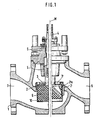
- valve 1 shows a globe valve of a known type, slightly different embodiments being shown on the right and left of the center axis M of the valve spindle 4 in relation to the configuration of the valve cone and valve seat.
- the valve shown in FIG. 1 has a valve housing 1 with an inlet connection 7 and an outlet connection 8. Inside the valve housing, a valve seat 2 or 2 'is arranged, which is opposite a valve cone 3 or 3' arranged at the inner end of the valve spindle 4 .
- a valve seat 2 or 2 ' is arranged, which is opposite a valve cone 3 or 3' arranged at the inner end of the valve spindle 4 .
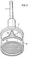
- an extension 10 which extends in the closing direction and is sealingly guided through the valve seat 2 or 2 ′, is arranged, in which an installation element 9 is arranged, which is only indicated schematically in FIGS. 1 and 2 and is explained in more detail below with reference to FIGS. 3 and 4.
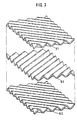
- the installation element 9 is made up of individual, mutually parallel lamellae which are parallel to one another and parallel to the axis of the projection 10, of which three in FIG. Lamens 9.1, 9.2 and 9.3 are shown exploded.
- the lamellae have a straight corrugation and are arranged so that the directions of the corrugations run obliquely to the axis of the shoulder 10. It is also possible to use slats with a curved corrugation.
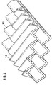
- the lamellae are further arranged such that the directions of the corrugations of two adjacent lamellae, for example lamellae 9.2 and 9.3, intersect.
- a built-in element made up of a plurality of lamellae is created, which is interspersed with a multiplicity of flow channels which branch again and again and connect with one another.
- the built-in element is to have a cylindrical shape
- the lamellae are designed such that the width increases from the outside inwards in the case of the successive lamellae.
- the result is a cylindrical block, which is used in the approach 10 so that the slats themselves run parallel to the cylinder axis.
- the directions of the corrugations on the other hand, each run obliquely to the cylinder axis and form an acute angle with one another in the case of adjacent slats.
- the flow direction is expediently selected parallel to the levels of the lamellae, i.e. it can either be flowed towards in the direction of the end faces of the cylindrical installation element or in the direction toward the lateral surface which corresponds to the direction of the lamellae.
- the medium can flow in through the inflow nozzle 7 from below against the valve cone 3, it enters the opening 10 which is open at the bottom and the installation element 9 is thus flowed from the lower end face.
- a passage opening 11 is provided in the lateral surface of the extension 10, through which the medium emerges when the valve cone 3 is raised.
- the shape of this passage opening is chosen. that it is composed of a slot 11.1 which extends in the circumferential direction of the projection 10 over a certain angular range and an opening 11.2 which adjoins this slot to the side of the valve cone 3 and tapers in this direction.
- the tapering opening 11.2 has a contour that essentially corresponds to a bell curve.
- This particular embodiment of the passage opening 11 has the purpose of achieving a linear characteristic curve for the valve shown in FIG. 1. It turned out to be. that the installation element described has a passage characteristic which, as the opening increases, is flattened and curved upward.
- the connector 8 can thus also serve as an inlet connector, the medium entering the installation element 9 through the passage opening 11 and exiting down to the connector 7.
- the installation element described can also be used with globe valves of other types, for example it can also be shaped as an outer cone.
- a conventional globe valve of the type shown in FIG. 1 can be converted without a noise-damping element, for example by retrofitting a valve cone, as shown in FIG. 2.
- the length and the diameter of the built-in element 9 depend on the space available and the desired noise reduction. It has been shown that a ratio of length to Diameter up to max. 2 is sufficient.
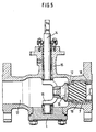
- a rotary plug valve is shown, with a housing 1, an inlet connector 17 and an outlet connector 18 and a rotary cone 13 arranged in the housing, which is connected via a connecting element 15 to the rotatable spindle 14 which is guided into the housing via a bushing 16.
- an installation element 19 which extends over the entire passage cross section and which also. as the installation element 9 described above has a cylindrical shape and is constructed in the same way as described with reference to FIGS. 3 and 4 from adjacent slats provided with corrugations.
- the Cylinder axis arranged and the corrugations each run obliquely to this cylinder axis, the corrugations intersecting in the manner already described from adjacent slats.
- the flow direction runs from one end surface to the other, that is to say parallel to the cylinder axis Z.
- the end surface of the installation element 19 facing the valve cone 13 is of the coherent shape of the sealing sealing on the sealing surface of the valve cone 13.
- valve seat 12 is formed by the concavely spherically curved end face of the installation element 19.
- valve cone 13 is opened by pivoting, an increasingly larger inflow surface on the installation element 19 is released.
- a particularly good noise-reducing effect is achieved by the direct inflow of the medium at the valve seat into the installation element 19. It continued to emerge !! that a characteristic curve is achieved in the rotary plug valve with the special design and arrangement of the built-in element 19. which influences the natural characteristic of a rotary plug valve in such a way that it becomes more linear at least in the wider opening range.
- the valve can also be provided with a soft sealing valve cone, which can be achieved, for example, by arranging an O-ring (not shown) in the sealing surface of the valve cone 13.
Landscapes
- Engineering & Computer Science (AREA)
- General Engineering & Computer Science (AREA)
- Mechanical Engineering (AREA)
- Details Of Valves (AREA)
- Lift Valve (AREA)
Description
- Die Erfinaung betrifft ein geräuscharmes Steliventil mit einem Gehäuse. in dem ein gegenüber einem Ventusitz bewegDarer, den Durchtrittsweg des Mediums sperrender oder öffnender Ventilkegel angeordnet ist und das einen Zuflußstutzen und einen Abflußstutzen besitzt und bei dem innerhalb des Gehäuses im Durchtrittsweg des Mediums ein geräuschdämpfendes Element angeordnet ist, wobe: innerhaib dieses Elementes der Durchtrittsweg des Mediums in eine Vielzahl von Teilwegen aufgeteilt ist und die Durchtrittsquerschnitte der Teilwege klein gegenüber dem Durchtrittsquerschnitt des Ventils sind.
- Derartige geräuscharme Stellventile sind an sich bekannt (z.B. aus der DE-A 2 448 295).
- Als geräuschdämpfende Elemente dienen beispielsweise im Durchtrittsweg angeordnete Lochkäfige oder im Zufluß oder Abfluß angeordnete Widerstandspakete.
- Die bekannten geräuschdämpfenden Elemente benötigen, wenn mit ihnen eine ausreichende Schallpegelsenkung von etwa 20 dBA, erreiht weraer. sol' relativ viel Enbauraum und aufwendge Kc-struktionen.
- Die der Erfindung zugrunde liegende Aufgabe bestand darin, ein geräuscharmes Steliventii der eingangs erwähnten Bauart zu schaffen, bei dem geräuschdämpfende Element bei guter WirKSamkeit reaitiv wenig Platz be nötigt. Weiterhin sollte erreicht werden. daß neben der Geräuschminderung eine Verschiebung des Kavitationsanfangs erreicht wird und daß die Anströmrichtung des Ventiis nicht vorgeschrieben ist. Schließlich sollte es möglich sein, trotz des Vorhandenseins eines geräuschdämpfenden Eiementes bestimmte, beispieisweise lineare Kennlinien des Ventils zu erreichen.
- Die Lösung dieser Aufgabe geschieht mit den Merkmalen aus dem kennzeichnenden Teil des Patentanspruchs 1. Vorteilhafte Ausführungsformen des erfindundsgemäßen Stellventils sind in den Unteransprüchen beschrieben.
- Der Grundgedanke der Erfindung besteht darin, als geräuschdämpfendes Element ein Einbauelement zu verwenden, das an sich bekannt ist, aber bisher für völlig andere technische Zwecke eingesetzt wurde. Ein solches Einbauelement ist beispielsweise in der CH-A 398 503 beschrieben. Das dort beschriebene Einbauelement wird in Stoffaustauschkolonnen, z.B. Rektifikationskolonnen, Kühltürmen oder Luftbefeuchtem verwendet, in welchen ein Gas oder eine Flüssigkeit im Gegenstrom geführt und in Kontakt gebracht werden.
- Weiterhin ist es auch bekanntgeworden (DE-C 2 205 371) ein derartiges Einbauelement als statischen Mischer für im Gleichstrom fließende Medien zu verwenden.
- Es hat sich nun herausgestelt, daß dieses Einbauelement in hervorragender Weise als geräuschdämpfendes Element in einem Stellventil verwendet werden kann. Es werden bei kleinem Einbauraum hervorragende Werte für die Schallpegelsenkung erreicht. Außerdem hat sich gezeigt, daß die Anwendungsmöglichkeiten dieses Einbauelementes innerhalb des Stellventils sehr vielfältig sind. So kann das in der erfindungsgemäßen Weise verwendete Embauelement im Zufluß, im Abfiuß oder aucn unmittelbar im oder am Ventilkegel oder im ode- am Ventilsitz angeordnet sein. Wie weiter unten näher ausgeführt, eröffnet der kleine Einbauraum, de7 dieses Einbauelement benötigt, die Möglichkeit, herkömmliche Ventile mit einem geräuschdämpfenden Element nachzurüsten.
- Die starke Verschiebung des Kavitationsanfangs bei Verwendung des erfindungsgemäßen Einbauelementes macht es möglich, mit höheren Differenzdrücken zu arbeiten.
- Das geräuschdämpfende Element nach der Erfindung kann aus allen formbaren Werkstoffer a'ss beispieisweise einerseits aus Metall und andererseits aus Kunststoff, hergestellt sein.
- Es kann bei sehr unterschiedlichen Ventilkonstruktionen, also einerseits bei Hubventilen und andererseits bei Drehkegelventilen verwendet werden.
- Es kann weiterhin so angeordnet sein, daß die Durchströmrichtung des Ventils nicht vorgeschrieben is:.
- Wie weiter unteranhard von ausführungsbe spieien näher erläutert, ist es möglich, auch bei Verwendung des erfindungsgemäßen Einbaue ementes bestimmte Kennlinienformen eines Ventils zu erhaiten.
- Bei einer besonders vorteilhaften, weiter unten näher erläuterten Ausführungsform an einem Hubventil ist das Einbauelement im Ventilkeae: angeordnet. Bei dieser Ausführungsform ist in besongerer Weise die Umrüstbarkeit eines herkömmlichen Ventils bei Erhaltung seiner beispielsweise linearen Kennlinie möglich.
- Bei einer anderen vorteilhaften Ausführungsform an einem Drehkegelventil ist es möglich, das erfindungsgemäße Einbauelement selbst als Ventilsitz auszubilden, wodurch ein besonders günstiger geräuschdämpfender Effekt erreicht wird.
- Im folgenden werden anhand der beigefügten Zeichnungen Ausführungsbeispiele für des Stellventil nach der Erfindung näner enautert.
- In den Zeichnungen zeigen:
- Fig. 1 im Längsschnitt ein Hubventil mit einem geräuschdämpfenden Element;
- Fig. 2 in perspektivischer vergrößerter Darstellung den Ventilkegel mit geräuschdämpfendem Eiement am Hubventil nach Fig. 1;
- Fig. 3 in explodierter perspektivischer Teildarstellung Einzelheiten des geräuschdämpfenden Elementes am Hubventil nach Fig. 1 und 2;
- Fig. 4 in zusammengesetzter perspektivischer Teildarstellung die Einzelheiten nach Fig. 3;
- Fig. 5 im Längsschnitt ein Drehkegelventil mit geräuschdämpfendem Element.
- In Fig. 1 ist ein Hubventil bekannter Bauart dargestellt, wobei rechts und links der Mitteiachse M der Ventilspindel 4 im Bezug auf die Ausbildung von Ventilkegel und Ventilsitz leicht unterschiedliche Ausführungsformen dargestellt sind.
- Das in Fig. 1 dargestellte Ventil besitzt ein Ventilgehäuse 1 mit einem Zuflußstutzen 7 und einem Abflußstutzen 8. Im Inneren des Ventilgeshäuses ist ein Ventusitz 2 bzw. 2' angeordnet, dem ein am inneren Ende der Ventilspindel 4 angeordneter Ventilkegel 3 bzw. 3' gegenüberliegt. Durch Anheben oder Absenken der über Durchführungen 5 und 6 in das Gehäuse hineingeführten Ventilspindel 4 wird der Ventilkegel 3 bzw. 3' vom Ventilsitz 2 bzw. 2' mit Einsatzstück 2'a abgehoben oder auf ihn aufgesetzt, wodurch die Öffnung oder Schließung des Ventils bewirkt wird.
- An der dem Ventilsitz 2 zugewandten Seite des Ventilkegels 3 ist, wie genaue- aus Fig. 2 zu entnehmen, ein sich in Schließrichtung erstreckender, durch den Ventilsitz 2 bzw. 2' dichtend hindurchgeführter, nach unten offener Ansatz 10 angeordnet, in dem ein Einbauelement 9 angeordnet ist, das in Fig. 1 und 2 nur schematisch angedeutet ist und im folgenden anhand der Fig. 3 und 4 näher erläutert wird.
- Das Einbauelement 9 ist aus einzelnen, parallel zueinander und parallel zur Achse des Ansatzes 10 stehenden, einander berührenden Lamellen aufgebaut, von denen In Fig. 3 dre. Lamenen 9.1, 9.2 und 9.3 explodier darcestellt sind De Lamellen weisen eine gradlinige Riffelung auf und sind so angeordnet, daß die Richtungen der Riffelungen schräg zur Achse des Ansatzes 10 verlaufen. Es ist auch möglich, Lamellen mit einer gekrümmt verlaufenden Riffelung zu verwenden. Wie besonders gut aus Fig. 4 zu entnehmen, sind die Lamellen weiterhin so angeordnet, daß sich die Richtungen der Riffelungen von je zwei benachbarten Lamellen, also beispielsweise den Lamellen 9.2 und 9.3, schneiden.
- Es entsteht auf diese Weise ein aus einer Vielzahl von Lamellen aufgebautes Einbauelement, das von einer Vielzahl von sich immer wieder verzweigenden und miteinander verbindenden Strömungskanälen durchsetzt ist. Wenn, wie bei dem in Fig. 1 und 2 dargestellten Ausführungsbeispiel das Einbauelement zylindrische Form besitzen soll, sind die Lamellen so ausgebildet, daß bei den aufeinanderfolgenden Lamellen die Breite von außen nach innen zunimmt. Es entsteht somit ein zylindrischer Block, der im Ansatz 10 so eingesetzt ist, daß die Lamellen selbst parallel zur Zylinderachse verlaufen. Die Richtungen der Riffelungen dagegen verlaufen jeweils schräg zur Zylinderachse und schließen bei benachbarten Lamellen miteinander einen spitzen Winkel ein.
- Bezüglich der Anströmrichtung des beschriebenen Einbauelementes bestehen verschiedene Möglichkeiten. Zweckmäßig wird die Anströmrichtung parallel zu den Ebenen der Lamellen gewählt, d.h. es kann entweder in Richtung der Stirnflächen des zylindrischen Einbauelementes oder in der Richtung auf die Mantelfläche zu angeströmt werden, die der Richtung der Lamellen entspricht.
- Bei dem dargestellten Ausführungsbeispiel kann also beispielsweise das Medium durch den Zuflußstutzen 7 eintretend von unten gegen den Ventilkegel 3 anströmen, wobei es in den unten offenen Ansatz 10 eintritt und somit das Einbauelement 9 von der unteren Stirnfläche her angeströmt wird.
- Wie Fig. 2 zu entnehmen, ist in der Mantelfläche des Ansatzes 10 eine Durchtrittsöffnung 11 vorgesehen, durch die beim Anheben des Ventilkegels 3 das Medium austritt. Die Form dieser Durchtrittsöffnung ist so gewählt. daß sie sich aus eine- sich in Umfangsrichtung des Ansatzes 10 über einen bestimmten Winkelbereich erstreckenden Schlitz 11.1 und einer sich an diesen Schlitz zur Seite des Ventilkegels 3 hin anschließenden und sich in dieser Richtung verjüngenden Öffnung 11.2 zusammensetzt. Die sich verjüngende Öffnung 11.2 hat dabei eine Kontur, die im wesentuchen einer Giockenkurve entspricht. Diese besondere Ausbildung der Durchtrittsöffnung 11 hat den Zweck, eine lineare Kennlinie für das in Fig. 1 dargestellte Ventil zu erreichen. Es hat sich nämlich herausgestellt. daß das beschriebene Einbauelement eine Durchtrittskennunie besitzt, die bei zunehmender Öffnung nach oben abflachend gekrümmt verläuft. Die genaue Form der Glockenkurve des Öffnungsteils 11.2 wird nun so berechnet, daß die Gesamtöffnung 11 für sich allein eine Kennlinie erzeugt. die entgegengesetzt gekrümmt ist, wie die Kennlinie des Einbauelementes 9. Wie unmittelbar an Fig. 2 abzulesen, erweitert sich der Durchtrittsquerschnitt der Durchtrittsönnung 11 beim Öffnen des Ventils stärken a's linear Durch die Überlagerung aer beiden Kennlinien des Einbauelementes 9 und der Durchtrittsöffnung 11 wird insgesamt eine lineare Kennlinie erreicht.
- Selbstverständlich kann dieser Ausgleich der Kennlinien auch durch andere Öffnungsformen im Mantel des Ansatzes 10 erreicht werden.
- So können beispielsweise auch mehrere in der Mantelfläche verteilte Durchtrittsöffnungen, beispielsweise Bohrungen, vorhanden sein, deren Dichte und/oder Durchmesser in Richtung auf den Ventilkegel 3 abnimmt. Diese Abnahme kann wiederum so eingestelt sein, daß sich ein Ausgleich der Durchtrittskennlinien und somit insgesamt eine lineare Kennlinie ergibt.
- Selbstverständlich ist bei dem in Fig. 1 und 2 dargestellten Hubventil die Durchströmungsrichtung nicht vorgeschrieben. Es kann also auch der Stutzen 8 als Zuflußstutzen dienen, wobei das Medium durch die Durchtrittsöffnung 11 in das Einbauelement 9 eintritt und nach unten zum Stutzen 7 hin austritt.
- Durch die Vielzahl der sich innerhalb des Einbauelementes 9 bildenden Teilströme des Mediums, die sich immer wieder kreuzen, erfolgt eine starke Energieumwandiung und eine entsprechende Geräuschminderung.
- Selbstverständlich ist das beschriebene Einbauelement auch bei Hubventilen anderer Bauart verwendbar, beispielsweise kann es auch als Außenkegel geformt sein.
- Besonders vorteilhaft ist, daß ein konventionelles Hubventil der Bauart nach Fig. 1 ohne geräuschdämpfendes Element umgerüstet werden kann, indem beispielsweise ein Ventilkegel, wie er in Fig. 2 dargestellt ist, nachträglich eingebaut wird.
- Die Länge und der Durchmesser des Einbauelementes 9 richten sich nach den Platzverhältnissen und der erstrebten Geräuschminderung. Es hat sich gezeigt, daß ein Verhältnis von Länge zum Durchmesser bis max. 2 ausreichend ist.
- In Fig. 5 ist ein Drehkegelventil dargestellt, mit einem Gehäuse 1, einem Zuflußstutzen 17 und einem Abflußstutzen 18 und einem im Gehäuse angeordneten Drehkegel 13, der über ein Verbindungselement 15 mit der über eine Durchführung 16 ins Gehäuse hineingeführten drehbaren Spindel 14 verbunden ist.
- Dem Drehkegel 13 gegenüberliegend ist ein sich über den ganzen Durchtrittsquerschnitt erstreckendes Einbauelement 19 angeordnet, das ebenfalls. wie das weiter oben beschriebene Einbauelement 9, zyiindnsche Form besitzt und in der gleichen Weise, wie anhand von Fig. 3 und 4 bescnrieben, aus nebeneinanderhegenden, mit einer Riffelung versehenen Lamellen aufgebaut ist. DieZylinderachse angeordnet und die Riffelungen verlaufen jeweils schräg zu dieser Zylinderachse, wobei sich in der bereits beschriebenen Weise die Riffelungen von einander benachbarten Lamellen schneiden. Bei dem Einbauelement 19 verläuft die Durchströmungsrichtung von einer Stirnfläche zur anderen, also parallel zur Zylinderachse Z. Die dem Ventilkegel 13 zugewandte Stirnfläche des Einbauelementes 19 ist der sohärischen Form der Dich-
 dichtend an der Dichtungsfläche des Ventilkegels 13 an. Damit wird erreicht, daß der Ventilsitz 12 durch die konkav sphärisch gekrümmte Stirnfläche des Einbauelementes 19 gebildet wird. Beim Öffnen des Ventilkegels 13 durch verschwenken wird eine sich zunehmend vergrößernde Einströmfläche am Einbauelement 19 freigegeben. Durch das direkte Einströmen des Mediums am Ventilsitz in das Einbauelement 19 wird ein besonders guter geräuschmindernder Effekt erreicnt. Es hat sich weiterhin herausgeste!!t. daß bei dem Drehkegelventil mit der besonderen Ausbildung und Anordnung des Einbauelementes 19 eine Kennlinie erzielt wird. die die natürliche Kennlinie eines Drehkegelventils in der Weise beeinflußt, daß sie mindestens im weiteren Öffnungsbereich linearer wird.
- Selbstverständlich kann auch bei dem in Fig. 5 dargestellten Ventil die Durchströmungsrichtung gewechselt werden.
- Das Ventil kann auch mit einem weichdichtenden Ventilkegel versehen sein, was beispielsweise durch Anordnung eines nicht dargestellten O-Ringes in der Dichtfläche des Ventilkegels 13 erreicht werden kann.
Claims (7)
Applications Claiming Priority (2)
| Application Number | Priority Date | Filing Date | Title |
|---|---|---|---|
| DE3520555 | 1985-06-07 | ||
| DE19853520555 DE3520555A1 (de) | 1985-06-07 | 1985-06-07 | Geraeuscharmes stellventil |
Publications (2)
| Publication Number | Publication Date |
|---|---|
| EP0216992A1 EP0216992A1 (de) | 1987-04-08 |
| EP0216992B1 true EP0216992B1 (de) | 1989-06-14 |
Family
ID=6272761
Family Applications (1)
| Application Number | Title | Priority Date | Filing Date |
|---|---|---|---|
| EP86106868A Expired EP0216992B1 (de) | 1985-06-07 | 1986-05-21 | Geräuscharmes Stellventil |
Country Status (7)
| Country | Link |
|---|---|
| US (1) | US4693450A (de) |
| EP (1) | EP0216992B1 (de) |
| JP (1) | JPS622085A (de) |
| BR (1) | BR8602618A (de) |
| DE (2) | DE3520555A1 (de) |
| ES (2) | ES296882Y (de) |
| MX (1) | MX162925B (de) |
Families Citing this family (23)
| Publication number | Priority date | Publication date | Assignee | Title |
|---|---|---|---|---|
| US4889163A (en) * | 1987-02-05 | 1989-12-26 | Ab Tore J Hedback | Valve assembly |
| AT404293B (de) * | 1995-09-14 | 1998-10-27 | Ideal Standard | Wasserventiloberteil mit in einem gehäuse befindlichen keramischen dichtscheiben |
| US5931445A (en) * | 1995-11-15 | 1999-08-03 | Fisher Controls International, Inc. | Multi-vane flow rate stabilizer for throttling valves |
| US5765814A (en) * | 1995-11-15 | 1998-06-16 | Fisher Controls International, Inc. | Flow rate stabilizer for throttling valves |
| US5772178A (en) * | 1995-12-22 | 1998-06-30 | Rotatrol Ag | Rotary noise attenuating valve |
| DE19825151B4 (de) * | 1998-06-05 | 2005-01-27 | Detlef Joniskeit | Schalldämpfer für Pneumatikventile |
| DE19841215B4 (de) * | 1998-09-09 | 2007-10-31 | Vetec Ventiltechnik Gmbh | Drehkegelventil |
| DE29819769U1 (de) | 1998-11-05 | 1999-02-18 | A. u. K. Müller GmbH & Co KG, 40595 Düsseldorf | Eigenmediumbetätigtes Servoventil für Flüssigkeiten, insbesondere Magnetventil für sanitäre Armaturen |
| GB0014713D0 (en) * | 2000-06-16 | 2000-08-09 | 3M Innovative Properties Co | Pressure regulator for a respirator system |
| US6644625B1 (en) | 2000-08-11 | 2003-11-11 | L. R. Nelson | Pistol grip hose nozzle with proportional flow control |
| US7028712B2 (en) | 2002-07-17 | 2006-04-18 | Fisher Controls International Llc. | Skirt guided globe valve |
| DE20311032U1 (de) * | 2003-07-17 | 2004-11-25 | Cooper Cameron Corp., Houston | Antriebsvorrichtung |
| US7152628B2 (en) * | 2004-02-04 | 2006-12-26 | Robert Folk | Anti-cavitation valve assembly |
| US7690400B2 (en) | 2005-02-28 | 2010-04-06 | Flowserve Management Company | Noise reducing fluid passageways for fluid control devices |
| US7500491B2 (en) * | 2006-04-13 | 2009-03-10 | V. Q. Corp. | Sanitary fluid pressure control valve |
| CA2584955C (en) * | 2006-05-15 | 2014-12-02 | Sulzer Chemtech Ag | A static mixer |
| CN101573547B (zh) * | 2006-05-15 | 2013-09-18 | 宋永生 | 阀门 |
| DE202008013969U1 (de) * | 2008-10-20 | 2009-01-08 | Bürkert Werke GmbH & Co. KG | Ventil mit variablem Durchfluss |
| US9010371B2 (en) | 2011-12-16 | 2015-04-21 | Cla-Val Co. | Anti-cavitation valve seat |
| CN103292030A (zh) * | 2013-06-18 | 2013-09-11 | 苏州德兰能源科技有限公司 | 一种多级降压排污阀 |
| WO2021016385A1 (en) * | 2019-07-24 | 2021-01-28 | Docherty Michael | Improved endoscope valve apparatus |
| US11359728B2 (en) | 2020-10-07 | 2022-06-14 | Griswold Industries | Anti-cavitation valve assembly |
| DE202022106088U1 (de) * | 2022-10-28 | 2022-12-07 | Samson Aktiengesellschaft | Ventilglied für ein Stellventil |
Citations (1)
| Publication number | Priority date | Publication date | Assignee | Title |
|---|---|---|---|---|
| CH398503A (de) * | 1962-07-31 | 1966-03-15 | Sulzer Ag | Stoffaustauschkolonne |
Family Cites Families (15)
| Publication number | Priority date | Publication date | Assignee | Title |
|---|---|---|---|---|
| US977427A (en) * | 1907-09-07 | 1910-12-06 | Charles G Armstrong | Pressure-reducer. |
| CH537208A (de) * | 1971-04-29 | 1973-07-13 | Sulzer Ag | Mischeinrichtung für fliessfähige Medien |
| JPS4981924A (de) * | 1972-12-12 | 1974-08-07 | ||
| FR2270502B1 (de) * | 1974-05-10 | 1978-01-13 | Masoneilan Int Inc | |
| DE2448295A1 (de) * | 1974-10-10 | 1976-04-22 | Gulde Regelarmaturen Kg | Drosselstrecke mit aufgeteilten stroemungsquerschnitten und regelbarem widerstand |
| FR2306390A1 (fr) * | 1975-03-19 | 1976-10-29 | Adar Sa | Procede et moyens pour obtenir aisement des obturations reduites dans une vanne a cage |
| US4125129A (en) * | 1975-04-04 | 1978-11-14 | Masoneilan International, Inc. | Fixed and variable resistance fluid throttling apparatus |
| US4007908A (en) * | 1975-05-09 | 1977-02-15 | Masoneilan International, Inc. | Process and device for attenuating noise caused by a valve during the expansion of a fluid |
| JPS5314421A (en) * | 1976-07-26 | 1978-02-09 | Masoneilan Int Inc | Fluid throttling device having fixed and changable resister |
| JPS5455819A (en) * | 1977-10-12 | 1979-05-04 | Osaka Gas Co Ltd | Low noise valve |
| DE2810118C2 (de) * | 1978-03-09 | 1982-05-19 | Gulde-Regelarmaturen-Kg, 6700 Ludwigshafen | Absperr- und Drosselhahn |
| JPS56131878A (en) * | 1980-03-17 | 1981-10-15 | Toshiba Corp | Control valve |
| US4402485A (en) * | 1981-06-11 | 1983-09-06 | Fisher Controls Company, Inc. | Eccentrically nested tube gas line silencer |
| JPS59140968A (ja) * | 1983-01-31 | 1984-08-13 | Yamatake Honeywell Co Ltd | 単座型玉形弁用弁座およびその製造方法 |
| US4511258A (en) * | 1983-03-25 | 1985-04-16 | Koflo Corporation | Static material mixing apparatus |
-
1985
- 1985-06-07 DE DE19853520555 patent/DE3520555A1/de not_active Withdrawn
-
1986
- 1986-05-21 EP EP86106868A patent/EP0216992B1/de not_active Expired
- 1986-05-21 DE DE8686106868T patent/DE3663991D1/de not_active Expired
- 1986-06-05 BR BR8602618A patent/BR8602618A/pt not_active IP Right Cessation
- 1986-06-06 JP JP61131659A patent/JPS622085A/ja active Pending
- 1986-06-06 ES ES1986296882U patent/ES296882Y/es not_active Expired
- 1986-06-06 MX MX2724A patent/MX162925B/es unknown
- 1986-06-06 US US06/871,706 patent/US4693450A/en not_active Expired - Fee Related
-
1987
- 1987-06-16 ES ES1987296659U patent/ES296659Y/es not_active Expired
Patent Citations (1)
| Publication number | Priority date | Publication date | Assignee | Title |
|---|---|---|---|---|
| CH398503A (de) * | 1962-07-31 | 1966-03-15 | Sulzer Ag | Stoffaustauschkolonne |
Also Published As
| Publication number | Publication date |
|---|---|
| ES296882U (es) | 1988-02-16 |
| MX162925B (es) | 1991-07-12 |
| ES296659U (es) | 1987-12-16 |
| ES296882Y (es) | 1988-11-16 |
| EP0216992A1 (de) | 1987-04-08 |
| JPS622085A (ja) | 1987-01-08 |
| ES296659Y (es) | 1988-05-16 |
| US4693450A (en) | 1987-09-15 |
| BR8602618A (pt) | 1987-02-03 |
| DE3520555A1 (de) | 1986-12-11 |
| DE3663991D1 (en) | 1989-07-20 |
Similar Documents
| Publication | Publication Date | Title |
|---|---|---|
| EP0216992B1 (de) | Geräuscharmes Stellventil | |
| EP0216993B1 (de) | Regelorgan für gasförmige und flüssige Medien | |
| DE69830565T2 (de) | Druckmindervorrichtung | |
| DE69920818T2 (de) | Sequentieller mischplattenschieber | |
| DE102006043647A1 (de) | Klappenventilanordnung mit verbesserter Strömungscharakteristik | |
| CH625320A5 (de) | ||
| DE60015374T2 (de) | Spiralwärmetauscher | |
| DE60012328T2 (de) | Ventil | |
| DE3690279C2 (de) | Schieberventil | |
| DE10236053B4 (de) | Mischventil | |
| DE69004909T2 (de) | Mischventil mit Kugelhahn. | |
| DE19841215B4 (de) | Drehkegelventil | |
| DE69410588T2 (de) | Kartoucheboden für Monoblockhähne | |
| DE4422742C2 (de) | Hydraulisches Wegeventil, das insbesondere von einem Proportionalmagneten betätigbar ist | |
| DE3134280A1 (de) | Geraeuschdaempfungsvorrichtung fuer ein mischventil | |
| DE3625289C2 (de) | Sanitäres Mischventil | |
| EP1378693B1 (de) | Heizkörperventil | |
| EP0515965B1 (de) | Ventil zum Steuern oder Regeln des Durchflusses eines Strömungsmittels | |
| DE2325091B2 (de) | Gehaeuse fuer absperrschieber | |
| EP0253322B1 (de) | Geräuscharmes Hydraulik-Ventil | |
| DE1450575B1 (de) | Membranventil | |
| DE68922114T2 (de) | Mischventil mit kugelsteuerungsmechanik. | |
| DE3614117C2 (de) | ||
| EP0898100A2 (de) | Mehrwege-Mischventil | |
| DE102004049253A1 (de) | Thermostatventil |
Legal Events
| Date | Code | Title | Description |
|---|---|---|---|
| PUAI | Public reference made under article 153(3) epc to a published international application that has entered the european phase |
Free format text: ORIGINAL CODE: 0009012 |
|
| AK | Designated contracting states |
Kind code of ref document: A1 Designated state(s): DE FR GB IT |
|
| 17P | Request for examination filed |
Effective date: 19870818 |
|
| 17Q | First examination report despatched |
Effective date: 19880808 |
|
| GRAA | (expected) grant |
Free format text: ORIGINAL CODE: 0009210 |
|
| ITF | It: translation for a ep patent filed | ||
| AK | Designated contracting states |
Kind code of ref document: B1 Designated state(s): DE FR GB IT |
|
| RAP2 | Party data changed (patent owner data changed or rights of a patent transferred) |
Owner name: MASONEILAN HP + HP GESELLSCHAFT MIT BESCHRAENKTER |
|
| REF | Corresponds to: |
Ref document number: 3663991 Country of ref document: DE Date of ref document: 19890720 |
|
| GBT | Gb: translation of ep patent filed (gb section 77(6)(a)/1977) | ||
| ET | Fr: translation filed | ||
| PLBI | Opposition filed |
Free format text: ORIGINAL CODE: 0009260 |
|
| 26 | Opposition filed |
Opponent name: ARCA REGLER GMBH Effective date: 19900310 |
|
| ITTA | It: last paid annual fee | ||
| PLBM | Termination of opposition procedure: date of legal effect published |
Free format text: ORIGINAL CODE: 0009276 |
|
| STAA | Information on the status of an ep patent application or granted ep patent |
Free format text: STATUS: OPPOSITION PROCEDURE CLOSED |
|
| 27C | Opposition proceedings terminated |
Effective date: 19910520 |
|
| PGFP | Annual fee paid to national office [announced via postgrant information from national office to epo] |
Ref country code: FR Payment date: 19950316 Year of fee payment: 10 |
|
| PGFP | Annual fee paid to national office [announced via postgrant information from national office to epo] |
Ref country code: GB Payment date: 19950324 Year of fee payment: 10 |
|
| PGFP | Annual fee paid to national office [announced via postgrant information from national office to epo] |
Ref country code: DE Payment date: 19950630 Year of fee payment: 10 |
|
| PG25 | Lapsed in a contracting state [announced via postgrant information from national office to epo] |
Ref country code: GB Effective date: 19960521 |
|
| GBPC | Gb: european patent ceased through non-payment of renewal fee |
Effective date: 19960521 |
|
| PG25 | Lapsed in a contracting state [announced via postgrant information from national office to epo] |
Ref country code: FR Effective date: 19970131 |
|
| PG25 | Lapsed in a contracting state [announced via postgrant information from national office to epo] |
Ref country code: DE Effective date: 19970201 |
|
| REG | Reference to a national code |
Ref country code: FR Ref legal event code: ST |
|
| PG25 | Lapsed in a contracting state [announced via postgrant information from national office to epo] |
Ref country code: IT Free format text: LAPSE BECAUSE OF NON-PAYMENT OF DUE FEES;WARNING: LAPSES OF ITALIAN PATENTS WITH EFFECTIVE DATE BEFORE 2007 MAY HAVE OCCURRED AT ANY TIME BEFORE 2007. THE CORRECT EFFECTIVE DATE MAY BE DIFFERENT FROM THE ONE RECORDED. Effective date: 20050521 |