EP0213335B1 - Bead lock device - Google Patents
Bead lock device Download PDFInfo
- Publication number
- EP0213335B1 EP0213335B1 EP86109494A EP86109494A EP0213335B1 EP 0213335 B1 EP0213335 B1 EP 0213335B1 EP 86109494 A EP86109494 A EP 86109494A EP 86109494 A EP86109494 A EP 86109494A EP 0213335 B1 EP0213335 B1 EP 0213335B1
- Authority
- EP
- European Patent Office
- Prior art keywords
- bows
- hoops
- tire
- wheel rim
- onto
- Prior art date
- Legal status (The legal status is an assumption and is not a legal conclusion. Google has not performed a legal analysis and makes no representation as to the accuracy of the status listed.)
- Expired - Lifetime
Links
- 239000011324 bead Substances 0.000 title claims description 39
- 125000006850 spacer group Chemical group 0.000 claims description 6
- 238000000034 method Methods 0.000 claims description 5
- 229920005989 resin Polymers 0.000 claims description 5
- 239000011347 resin Substances 0.000 claims description 5
- 229920002430 Fibre-reinforced plastic Polymers 0.000 claims description 4
- 239000000835 fiber Substances 0.000 claims description 4
- 239000011151 fibre-reinforced plastic Substances 0.000 claims description 4
- 239000004593 Epoxy Substances 0.000 claims description 3
- 230000000295 complement effect Effects 0.000 claims description 3
- 239000000463 material Substances 0.000 claims description 3
- 229920000728 polyester Polymers 0.000 claims description 3
- 229920001567 vinyl ester resin Polymers 0.000 claims description 3
- 239000011521 glass Substances 0.000 claims description 2
- 239000002990 reinforced plastic Substances 0.000 claims 1
- 238000007789 sealing Methods 0.000 description 5
- 238000010276 construction Methods 0.000 description 3
- 230000007246 mechanism Effects 0.000 description 2
- 241000736839 Chara Species 0.000 description 1
- FYYHWMGAXLPEAU-UHFFFAOYSA-N Magnesium Chemical compound [Mg] FYYHWMGAXLPEAU-UHFFFAOYSA-N 0.000 description 1
- 239000004411 aluminium Substances 0.000 description 1
- 229910052782 aluminium Inorganic materials 0.000 description 1
- XAGFODPZIPBFFR-UHFFFAOYSA-N aluminium Chemical compound [Al] XAGFODPZIPBFFR-UHFFFAOYSA-N 0.000 description 1
- 239000003365 glass fiber Substances 0.000 description 1
- 239000011777 magnesium Substances 0.000 description 1
- 229910052749 magnesium Inorganic materials 0.000 description 1
- 239000011159 matrix material Substances 0.000 description 1
- 229910052751 metal Inorganic materials 0.000 description 1
- 239000002184 metal Substances 0.000 description 1
- 239000007769 metal material Substances 0.000 description 1
- 239000000203 mixture Substances 0.000 description 1
- 239000004033 plastic Substances 0.000 description 1
- 229920003023 plastic Polymers 0.000 description 1
Images

Classifications
-
- B—PERFORMING OPERATIONS; TRANSPORTING
- B60—VEHICLES IN GENERAL
- B60C—VEHICLE TYRES; TYRE INFLATION; TYRE CHANGING; CONNECTING VALVES TO INFLATABLE ELASTIC BODIES IN GENERAL; DEVICES OR ARRANGEMENTS RELATED TO TYRES
- B60C25/00—Apparatus or tools adapted for mounting, removing or inspecting tyres
-
- B—PERFORMING OPERATIONS; TRANSPORTING
- B60—VEHICLES IN GENERAL
- B60C—VEHICLE TYRES; TYRE INFLATION; TYRE CHANGING; CONNECTING VALVES TO INFLATABLE ELASTIC BODIES IN GENERAL; DEVICES OR ARRANGEMENTS RELATED TO TYRES
- B60C15/00—Tyre beads, e.g. ply turn-up or overlap
- B60C15/02—Seating or securing beads on rims
- B60C15/028—Spacers between beads
-
- B—PERFORMING OPERATIONS; TRANSPORTING
- B60—VEHICLES IN GENERAL
- B60C—VEHICLE TYRES; TYRE INFLATION; TYRE CHANGING; CONNECTING VALVES TO INFLATABLE ELASTIC BODIES IN GENERAL; DEVICES OR ARRANGEMENTS RELATED TO TYRES
- B60C17/00—Tyres characterised by means enabling restricted operation in damaged or deflated condition; Accessories therefor
- B60C17/04—Tyres characterised by means enabling restricted operation in damaged or deflated condition; Accessories therefor utilising additional non-inflatable supports which become load-supporting in emergency
-
- Y—GENERAL TAGGING OF NEW TECHNOLOGICAL DEVELOPMENTS; GENERAL TAGGING OF CROSS-SECTIONAL TECHNOLOGIES SPANNING OVER SEVERAL SECTIONS OF THE IPC; TECHNICAL SUBJECTS COVERED BY FORMER USPC CROSS-REFERENCE ART COLLECTIONS [XRACs] AND DIGESTS
- Y10—TECHNICAL SUBJECTS COVERED BY FORMER USPC
- Y10T—TECHNICAL SUBJECTS COVERED BY FORMER US CLASSIFICATION
- Y10T29/00—Metal working
- Y10T29/49—Method of mechanical manufacture
- Y10T29/49826—Assembling or joining
- Y10T29/49863—Assembling or joining with prestressing of part
-
- Y—GENERAL TAGGING OF NEW TECHNOLOGICAL DEVELOPMENTS; GENERAL TAGGING OF CROSS-SECTIONAL TECHNOLOGIES SPANNING OVER SEVERAL SECTIONS OF THE IPC; TECHNICAL SUBJECTS COVERED BY FORMER USPC CROSS-REFERENCE ART COLLECTIONS [XRACs] AND DIGESTS
- Y10—TECHNICAL SUBJECTS COVERED BY FORMER USPC
- Y10T—TECHNICAL SUBJECTS COVERED BY FORMER US CLASSIFICATION
- Y10T403/00—Joints and connections
- Y10T403/65—Scarf
- Y10T403/655—Mirror images
-
- Y—GENERAL TAGGING OF NEW TECHNOLOGICAL DEVELOPMENTS; GENERAL TAGGING OF CROSS-SECTIONAL TECHNOLOGIES SPANNING OVER SEVERAL SECTIONS OF THE IPC; TECHNICAL SUBJECTS COVERED BY FORMER USPC CROSS-REFERENCE ART COLLECTIONS [XRACs] AND DIGESTS
- Y10—TECHNICAL SUBJECTS COVERED BY FORMER USPC
- Y10T—TECHNICAL SUBJECTS COVERED BY FORMER US CLASSIFICATION
- Y10T403/00—Joints and connections
- Y10T403/75—Joints and connections having a joining piece extending through aligned openings in plural members
Definitions
- This invention relates to bead locking devices for use in combination with pneumatic vehicle tires and, more particularly, to devices for holding the annular beads of the tire against the circumferential flanges of the wheel rim at low tire pressures.
- the prior art bead locking devices teach the use of open structures, closed structures, and a combination of each, as well as pneumatic and mechanical sealing mechanisms.
- the prior art also teaches some form of cross member or run flat structure for supporting the tire during periods of low pressure.
- An open structure is one that has a space or gap between successive cross members.
- a closed structure is one in which the cross member is a continuous structure.
- a combination structure is a partially open and partially closed structure.
- a pneumatic seal uses air pressure to lock the tire bead in place.
- a mechanical seal uses a mechanical device to lock the tire bead in place.
- U.S.-A-2,844,180, 4,248,286, 4,293,016, 4,401,144 and DE-C-2,648,919 illustrate varying forms of a closed structure.
- U.S.-A-4,281,700 and 4,281,701 illustrate a form of combination run-flat and bead lock device.
- U.S.-A-4,153,095, 4,216,809, 4,246,948 and 4,262,724 illustrate a pneumatic sealing bead-lock device.
- U.S.-A-4,216,810 illustrates a mechanical sealing bead-lock device.
- the present invention for use with a pneumatic vehicle tire having a pair of annular bead involves a bead-lock device, with the tire being supported on a wheel rim with outer circumferential flanges as set out in claim 1.
- the bead-lock device comprises a plurality of generally U-shaped flexible bows and a frame means for connecting the bows together to form a unitary annular structure about the circumference of the wheel. A portion of each bow extends outwardly in a radial direction from the rim. The opposite ends of each bow are positioned so that they are adjacent to the inner sides of the tire beads. The bows are compressed when the tire is assembled onto the wheel. This assembly creates an axial force in the bows which presses the bows against the tire beads toward the respective flanges of the wheel, thus securing the tire onto the wheel even under low pressure conditions.
- Another aspect of the present invention is a method of assembling such a bead lock device. Opposite ends of a plurality of generally U-shaped flexible bows are attached to a pair of flexible rods at spaced locations on the rods. Then the opposite ends of the rods are connected together to form a pair of hoops, each with a diameter slightly larger than the diameter of the wheel. The formed annular unitary structure is then inserted into a tire. When the tire, containing the present invention bead-lock, is assembled on the wheel rim, the axial spring force of the bows urge the tire beads against their respective wheel flanges thereby securing the tire onto the wheel.
- the bows of the present invention are preferably made of fiber reinforced plastic using resins selected from the group of vinyl ester, polyester, epoxy or the like - resins yielding high strength, lightweight chara cteristics.
- the present invention also provides an easily repairable and inexpensive device for efficiently and reliably securing pneumatic vehicle tires onto a wheel having lateral circumferential flanges.
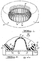
- the bead lock device 10 made in accordance with the teachings of the present invention has a plurality of bows 12 extending from a frame which, in this embodiment, is provided by a pair of hoops 14 and 15. Each bow 12 is positioned an equal distance from each successive bow 12 about the annular frame. A plurality of sleeves or collars 16 are positioned between each bow 12 forming a space or gap therebetween.
- the bead lock device 10 is shown in Figures 1 and 2 as positioned in a tire 18 which is mounted upon a wheel rim 20, and secured on the rim by a pair of lateral circumferential flanges 22 and 23. When assembled, the tire beads 24, 25 are compressed between the bead lock device 10 and the rim flanges 22, 23 thereby securing the tire 18 onto the wheel rim 20 even at low tire pressures.
- the bows 12 each have a U-shaped construction.
- Each bow's ends 26 and 27 are formed in a reversely curled configuration. These reversely curled ends 26, 27 or loops are threaded or snap fitted onto the hoops 14, 15 of the frame, respectively.
- the U-shaped bows 12 extend radially outward from the axis of the wheel assembly and thus may also serve as run flat devices.
- the bows 12 are manufactured of a fiber reinforced plastic.
- the fiber is preferably glass and the matrix resin is preferably vinyl ester, polyester, epoxy or the like.
- the glass fibers in the finished bows run continuously the length thereof (as illustrated diagrammatically by the phantom lines 13 in Figure 2) to provide the bows with excellent lightweight mechanical strength properties while still being capable of flexing to provide the necessary spring force.
- Each bow's U-shaped design enhances the sealing capacities of the bead lock device 10.
- the bows 12, positioned on the wheel, exert an axial force upon the inner surface of the tire beads 24, 25.
- the stationary wheel rim flanges 22, 23 exert a reactive axial force to the axial force of the bows 12 thereby locking the tire beads between the bead lock device and the wheel rim flanges.
- the configuration of the bow ends 26, 27 are such that they can be snapped or threaded onto the frame.
- the bows 12 may be loosely held on the frame or they may be held in place by a conventional fastener.
- the looped portion of the bow ends 26, 27 has an interior diameter approximately equal to the diameter of the frame hoops 14, 15. This enables the bow ends 26, 27 to be securely snapped or thread- . ed onto the frame. This fit provides the bows 12 with slight rotation about the frame which enables the bows 12 to exert continual axial force against the tire beads 24.
- the hoops 14, 15 making up the frame of the preferred embodiment each have a diameter slightly larger than the outside diameter of the wheel rim.
- Each hoop is preferably manufactured from fiber reinforced plastic, but it also can be made of aluminium, magnesium or the like - materials which possess high strength and lightweight properties.
- the hoops may be a wire cable or any suitable inner connecting link mechanism, such as a chain.
- the hoops of the preferred construction can be made by joining together the ends of suitable lengths of flexible rods.
- connector assembly 40 shown in Figure 4 can be used for this purpose.
- the connector assembly 40 employs a fastener 44 and a collar 46 to join the rod ends 41, 42 together to form each loop.
- the rod ends 41, 42 are formed with complementary step configurations for securing the ends together.
- a first step 48 is formed on the terminal portion of the rod end.
- a second step 50, adjacent to the first step 48, has an aperture 52 for passage of a fastener to secure the ends 41, 42 together.
- a third step 54, adjacent to the second step 50, is indented and has the complementary shape of the first step 48.
- the rod ends 41, 42 are interlockingly positioned upon one another, so that the second step apertures 52 are coaxial and the first step 48 of one rod end is positioned in the third step 54 of the other rod end.
- a fastener 44 such as a cotter pin, is used to join the two frame ends 42 together.
- the collar 46 of the connector assembly has a pair of coaxial apertures 47 through its surface, as will be described in detail below.
- the apertures 47 enable the fastener heads 60 to be housed in the collar 46 and prevents the projection of the fastener head 60 out of the device 10.
- Collars 16 are positioned between successive bows 12. Each collar 16 provides a gap between the successive bows 12. The gap 62 between the successive bows 12 is equally spaced.
- the collars 16 are preferably manufactured from plastic, metal, reinforced fiber resins, or the like - materials which exert high strength and lightweight characteristics.
- the collar 16 is a tubular member with an inside diameter approximately equal to the outside cross-sectional diameter of the hoop so that it can be threaded onto the hoop between the bows 12.
- the bead lock device is assembled by placing the bows 12 and collars 16 onto the unjoined rods.
- the collars 16 are threaded onto the frame 14. If the bows 12 are threaded onto the frame 14, the collars 16 will be threaded onto the hoop rods before and after each bow 12. If the bows 12 are snap fitted onto the frame 14, a predetermined number of collars 16 are threaded onto the hoop rods prior to the snapping on of the bows 12. The bows 12 then are snap fitted to the hoop rods between the collars 16.
- the ends 41, 42 of the rods are then interlocked and the apertures 47 of special collar 46 are positioned coaxially with the apertures 52 in the ends of the rods.
- Fastener 44 is then passed through apertures 47, 52 for securing the rods together to form hoops 14, 15 and complete the construction of the bead lock device 10.
- the collar 46 of the connector assembly has substantially the same thickness and width as the other collars 16. Consequently, the connection of the rods blends in with the outline of the remaining structural components.
- the bead lock device 10 is then ready to be placed into a pneumatic vehicle tire.
- the tire beads 24 are pried open either by manual force or by conventional pneumatic tire spreaders. With the beads 24 spread, the bead lock device 10 may be inserted into the tire 18 as a completed structure or in a coiled configuration where the hoop ends have not been connected. In the latter case, stops (not shown) should be placed on the rod ends 41, 42 to prevent the bows 12 and collars 16 from sliding off.
- One end of the partially assembled device is threaded into the interior of the tire 18, with a portion of the device remaining outside of the tire 18 being in a helical pattern. The helical portion remaining outside of the tire 18 is gradually threaded into the tire 18 until the rod ends 42 come together. Then, rod ends 41, 42 are secured together with the connector assembly forming the completed bead lock device 10, as described herein.
- the tire 18, with the assembled bead lock device 10 in its interior, is then ready to be placed onto wheel 20.
- the wheel 20 has one stationary flange 22 and a second removable flange 23 held in place by a suitable ring 21.
- the flange 23 With the flange 23 removed, the tire 18 and device 10 within it are slid into wheel 20. Then the flange 23 is pressed down onto the subassembly and the ring 21 is locked into place.
- the bows 12 are axially compressed and serve as springs acting to hold the beads 24, 25 against the wheel flanges 22, 23, respectively.
Landscapes
- Engineering & Computer Science (AREA)
- Mechanical Engineering (AREA)
- Tires In General (AREA)
Applications Claiming Priority (2)
| Application Number | Priority Date | Filing Date | Title |
|---|---|---|---|
| US772006 | 1985-09-03 | ||
| US06/772,006 US4674549A (en) | 1985-09-03 | 1985-09-03 | Bead lock device |
Publications (3)
| Publication Number | Publication Date |
|---|---|
| EP0213335A2 EP0213335A2 (en) | 1987-03-11 |
| EP0213335A3 EP0213335A3 (en) | 1988-04-20 |
| EP0213335B1 true EP0213335B1 (en) | 1990-11-07 |
Family
ID=25093603
Family Applications (1)
| Application Number | Title | Priority Date | Filing Date |
|---|---|---|---|
| EP86109494A Expired - Lifetime EP0213335B1 (en) | 1985-09-03 | 1986-07-11 | Bead lock device |
Country Status (10)
| Country | Link |
|---|---|
| US (1) | US4674549A (mo) |
| EP (1) | EP0213335B1 (mo) |
| KR (1) | KR920003232B1 (mo) |
| CN (1) | CN86104999B (mo) |
| BR (1) | BR8604133A (mo) |
| CA (1) | CA1267828A (mo) |
| DE (1) | DE3675469D1 (mo) |
| IN (1) | IN165581B (mo) |
| MX (1) | MX163950B (mo) |
| ZA (1) | ZA864957B (mo) |
Families Citing this family (12)
| Publication number | Priority date | Publication date | Assignee | Title |
|---|---|---|---|---|
| US4823854A (en) * | 1986-01-27 | 1989-04-25 | Motor Wheel Corporation | Safety tire and rim combination with safety insert |
| US4964842A (en) * | 1988-08-23 | 1990-10-23 | Martin Sprocket And Gear | Two piece power transmission component |
| US5363894A (en) * | 1988-09-15 | 1994-11-15 | Compagnie Generale Des Etablissements Michelin-Michelin & Cie | Safety support to be incorporated inside a tire |
| DE19825311C1 (de) * | 1998-06-05 | 2000-02-24 | Continental Ag | Fahrzeugrad mit einem Notlaufstützkörper |
| US6527346B2 (en) | 2001-07-11 | 2003-03-04 | James Chen | Removable vehicle wheel ring |
| US7201197B2 (en) * | 2002-07-24 | 2007-04-10 | The Yokohama Rubber Co., Ltd. | Tire/wheel assembly |
| JP4079714B2 (ja) * | 2002-07-25 | 2008-04-23 | 横浜ゴム株式会社 | ランフラットタイヤ及びタイヤホイール組立体 |
| US6820669B2 (en) | 2002-10-07 | 2004-11-23 | Tezzen Wheel Corporation | Wheel with extended outer flange |
| JP2004161161A (ja) * | 2002-11-14 | 2004-06-10 | Yokohama Rubber Co Ltd:The | タイヤ/ホイール組立体 |
| KR20050102665A (ko) * | 2003-02-21 | 2005-10-26 | 요코하마 고무 가부시키가이샤 | 타이어/휠 조립체 및 런 플랫용 지지체 |
| JP2007302136A (ja) * | 2006-05-12 | 2007-11-22 | Yokohama Rubber Co Ltd:The | ランフラット用支持体及びその組み付け方法 |
| US8474494B2 (en) | 2011-06-06 | 2013-07-02 | Patrick Clancy and Georgene Pappas, a Partnership | Roadside repair kit for restoring tire bead integrity |
Family Cites Families (31)
| Publication number | Priority date | Publication date | Assignee | Title |
|---|---|---|---|---|
| US495277A (en) * | 1893-04-11 | Vehicle-tire | ||
| US1324944A (en) * | 1919-12-16 | Air-cooled vehicle-tire | ||
| US1213557A (en) * | 1916-05-20 | 1917-01-23 | John Thomas Trotter | Tire. |
| US2053245A (en) * | 1935-12-23 | 1936-09-01 | Clarence J Bertschy | Noncollapsible pneumatic tire |
| US2381382A (en) * | 1941-08-22 | 1945-08-07 | Firestone Tire & Rubber Co | Bead lock |
| GB555754A (en) * | 1942-07-30 | 1943-09-06 | Firestone Tire & Rubber Co | Improvements in or relating to means for maintaining a pneumatic tyre in correct position upon a wheel rim even when the tyre is used in a deflated condition |
| DE1021737B (de) * | 1955-03-21 | 1957-12-27 | Max Boehm | Abdichtung eines schlauchlosen Kraftfahrzeugreifens gegen die Felge |
| US2844180A (en) * | 1955-04-25 | 1958-07-22 | Carl J E Omeron | Safety rim structure |
| FR1496371A (fr) * | 1966-10-11 | 1967-09-29 | Daimler Benz Ag | Bague de roulement de sûreté pour bandages sans chambre à air, en particulier pour jantes non divisées de roues de voitures automobiles |
| GB1305383A (mo) * | 1969-03-20 | 1973-01-31 | ||
| IT990553B (it) * | 1972-05-06 | 1975-07-10 | Dunlop Ltd | Perfezionamento negli elementi di ritegno di talloni di coper toni per assiemi di copertoni e cerchioni divisi per coperto ni pneumatici |
| US3828836A (en) * | 1972-12-13 | 1974-08-13 | C Bradley | Safety wheel and tire securing assembly |
| GB1556721A (en) * | 1976-08-23 | 1979-11-28 | Patecell T C | Run-flat insert for an inflatable tyre |
| DE2648919A1 (de) * | 1976-10-28 | 1978-05-11 | Lepper Gmbh Masch App | Schutzvorrichtung fuer kraftfahrzeuge |
| NL7706663A (en) * | 1977-06-16 | 1978-12-19 | Vredestein Nv | Rim, tyre and insert combination for combatting bursts - has support transferring load to beads and rim flange |
| US4153095A (en) * | 1977-09-14 | 1979-05-08 | Uniroyal, Inc. | Pneumatic tire having a pneumatic safety insert with beads |
| US4216809A (en) * | 1977-09-14 | 1980-08-12 | Uniroyal, Inc. | Pneumatic tire having a run-flat insert structure |
| US4137960A (en) * | 1977-11-07 | 1979-02-06 | General Motors Corporation | Run-flat tire having internal support means |
| JPS5813366B2 (ja) * | 1978-01-19 | 1983-03-14 | オ−ツタイヤ株式会社 | 車輪 |
| GB2032856B (en) * | 1978-02-10 | 1982-07-28 | Nat Res Dev | Supporting deflated tyres |
| US4157107A (en) * | 1978-04-03 | 1979-06-05 | General Motors Corporation | Run-flat tire having integral internal support means |
| US4248286A (en) * | 1978-06-30 | 1981-02-03 | The Goodyear Tire & Rubber Company | Safety support assembly for pneumatic tires |
| US4246947A (en) * | 1978-07-28 | 1981-01-27 | Ewing Michael D | Vehicle tire |
| US4223713A (en) * | 1978-09-05 | 1980-09-23 | Ewing Michael D | Pneumatic tire having structural ribs |
| DE3008698A1 (de) * | 1979-03-07 | 1980-09-18 | Dunlop Ltd | Radfelge fuer luftreifen |
| US4281700A (en) * | 1979-04-26 | 1981-08-04 | W. R. Grace & Co. | Run-flat vehicle tire |
| US4262724A (en) * | 1979-05-03 | 1981-04-21 | Uniroyal, Inc. | Low pressure and run-flat warning system for a pneumatic tire |
| JPS55160610A (en) * | 1979-06-02 | 1980-12-13 | Toyobo Co Ltd | Safety tire for motorcar |
| US4246948A (en) * | 1979-06-14 | 1981-01-27 | Uniroyal, Inc. | Pneumatic tire having a pneumatic safety insert with beads |
| US4281701A (en) * | 1980-02-15 | 1981-08-04 | W. R. Grace & Co. | Vehicle tire having run flat insert |
| US4293016A (en) * | 1980-03-24 | 1981-10-06 | The General Tire & Rubber Co. | Pneumatic tire assembly |
-
1985
- 1985-09-03 US US06/772,006 patent/US4674549A/en not_active Expired - Fee Related
-
1986
- 1986-07-03 ZA ZA864957A patent/ZA864957B/xx unknown
- 1986-07-08 IN IN504/CAL/86A patent/IN165581B/en unknown
- 1986-07-11 EP EP86109494A patent/EP0213335B1/en not_active Expired - Lifetime
- 1986-07-11 DE DE8686109494T patent/DE3675469D1/de not_active Expired - Lifetime
- 1986-07-18 MX MX3184A patent/MX163950B/es unknown
- 1986-07-22 CA CA000514399A patent/CA1267828A/en not_active Expired - Lifetime
- 1986-08-16 CN CN86104999A patent/CN86104999B/zh not_active Expired
- 1986-08-29 BR BR8604133A patent/BR8604133A/pt unknown
- 1986-09-02 KR KR1019860007313A patent/KR920003232B1/ko not_active Expired
Also Published As
| Publication number | Publication date |
|---|---|
| MX163950B (es) | 1992-07-03 |
| CN86104999B (zh) | 1988-07-27 |
| CN86104999A (zh) | 1987-03-04 |
| KR870002961A (ko) | 1987-04-14 |
| IN165581B (mo) | 1989-11-25 |
| KR920003232B1 (ko) | 1992-04-25 |
| ZA864957B (en) | 1987-02-25 |
| DE3675469D1 (de) | 1990-12-13 |
| EP0213335A2 (en) | 1987-03-11 |
| US4674549A (en) | 1987-06-23 |
| EP0213335A3 (en) | 1988-04-20 |
| CA1267828A (en) | 1990-04-17 |
| BR8604133A (pt) | 1987-04-22 |
Similar Documents
| Publication | Publication Date | Title |
|---|---|---|
| EP0213335B1 (en) | Bead lock device | |
| EP0295393B1 (en) | End cap assembly for air spring | |
| US5885387A (en) | Pneumatic tire having endless carcass cord ply | |
| US3717315A (en) | Take-apart spool for wire and the like | |
| DE3711696A1 (de) | Wulstkern fuer einen fahrzeugluftreifen | |
| AU2008243185A1 (en) | Rim for a bicycle wheel and bicycle wheel comprising such a rim | |
| US4797987A (en) | Method of assembling a bead lock device and pneumatic tire | |
| US4122882A (en) | Wheel rim | |
| US4140289A (en) | Disposable, wire storage and pay-out spool | |
| JPS6290227A (ja) | 空気タイヤを製造する方法および成形具 | |
| JP2002192921A (ja) | らせん六角ビードおよび製造方法 | |
| US5060706A (en) | Bead retainer | |
| US5971317A (en) | Warp resistant molded plastic reel | |
| FI82217B (fi) | Kombination av pneumatiskt daeck och hjulfaelg. | |
| AU609470B2 (en) | Improvements in the beads of pneumatic tyres for vehicle wheels | |
| DE2364274A1 (de) | Luftreifen fuer fahrzeugraeder | |
| US11833866B2 (en) | Web structure for non-pneumatic tire and method of making same | |
| EP0397593B1 (en) | Bead retainer | |
| GB2179009A (en) | Pneumatic tyres | |
| EP0658449B1 (en) | Toroidal carcass for road vehicle tires | |
| US4750763A (en) | Device for anchoring a flexible tubular system on a rigid shoulder by means of an armature with linked segments | |
| EP0400298A1 (en) | Offset wound helical bead for pneumatic tires | |
| DE3420402A1 (de) | Fahrzeugrad | |
| US4858297A (en) | Manufacturing method for a non-inflatable deformable wheel | |
| US4453583A (en) | Closed torus tire/rim assembly |
Legal Events
| Date | Code | Title | Description |
|---|---|---|---|
| PUAI | Public reference made under article 153(3) epc to a published international application that has entered the european phase |
Free format text: ORIGINAL CODE: 0009012 |
|
| AK | Designated contracting states |
Kind code of ref document: A2 Designated state(s): DE FR GB |
|
| 17P | Request for examination filed |
Effective date: 19870520 |
|
| PUAL | Search report despatched |
Free format text: ORIGINAL CODE: 0009013 |
|
| AK | Designated contracting states |
Kind code of ref document: A3 Designated state(s): DE FR GB |
|
| 17Q | First examination report despatched |
Effective date: 19900206 |
|
| GRAA | (expected) grant |
Free format text: ORIGINAL CODE: 0009210 |
|
| AK | Designated contracting states |
Kind code of ref document: B1 Designated state(s): DE FR GB |
|
| REF | Corresponds to: |
Ref document number: 3675469 Country of ref document: DE Date of ref document: 19901213 |
|
| ET | Fr: translation filed | ||
| PGFP | Annual fee paid to national office [announced via postgrant information from national office to epo] |
Ref country code: DE Payment date: 19910828 Year of fee payment: 6 |
|
| PLBE | No opposition filed within time limit |
Free format text: ORIGINAL CODE: 0009261 |
|
| STAA | Information on the status of an ep patent application or granted ep patent |
Free format text: STATUS: NO OPPOSITION FILED WITHIN TIME LIMIT |
|
| 26N | No opposition filed | ||
| PGFP | Annual fee paid to national office [announced via postgrant information from national office to epo] |
Ref country code: GB Payment date: 19920710 Year of fee payment: 7 |
|
| PGFP | Annual fee paid to national office [announced via postgrant information from national office to epo] |
Ref country code: FR Payment date: 19920713 Year of fee payment: 7 |
|
| PG25 | Lapsed in a contracting state [announced via postgrant information from national office to epo] |
Ref country code: DE Effective date: 19930401 |
|
| PG25 | Lapsed in a contracting state [announced via postgrant information from national office to epo] |
Ref country code: GB Effective date: 19930711 |
|
| GBPC | Gb: european patent ceased through non-payment of renewal fee |
Effective date: 19930711 |
|
| PG25 | Lapsed in a contracting state [announced via postgrant information from national office to epo] |
Ref country code: FR Effective date: 19940331 |
|
| REG | Reference to a national code |
Ref country code: FR Ref legal event code: ST |