EP0212397B1 - Fliessbettapparatur - Google Patents
Fliessbettapparatur Download PDFInfo
- Publication number
- EP0212397B1 EP0212397B1 EP86110681A EP86110681A EP0212397B1 EP 0212397 B1 EP0212397 B1 EP 0212397B1 EP 86110681 A EP86110681 A EP 86110681A EP 86110681 A EP86110681 A EP 86110681A EP 0212397 B1 EP0212397 B1 EP 0212397B1
- Authority
- EP
- European Patent Office
- Prior art keywords
- vessel
- approximately
- immersion tube
- bed apparatus
- fluidized bed
- Prior art date
- Legal status (The legal status is an assumption and is not a legal conclusion. Google has not performed a legal analysis and makes no representation as to the accuracy of the status listed.)
- Expired - Lifetime
Links
- 238000007654 immersion Methods 0.000 claims description 18
- 239000000463 material Substances 0.000 claims description 14
- 239000007788 liquid Substances 0.000 claims description 5
- 239000007787 solid Substances 0.000 claims description 5
- 239000008187 granular material Substances 0.000 claims description 3
- 230000003247 decreasing effect Effects 0.000 claims description 2
- 238000001035 drying Methods 0.000 claims description 2
- 239000007921 spray Substances 0.000 claims description 2
- 239000011248 coating agent Substances 0.000 claims 1
- 238000000576 coating method Methods 0.000 claims 1
- 239000007789 gas Substances 0.000 description 13
- 239000011324 bead Substances 0.000 description 4
- 238000005507 spraying Methods 0.000 description 4
- 239000000126 substance Substances 0.000 description 3
- 238000000034 method Methods 0.000 description 2
- 238000004140 cleaning Methods 0.000 description 1
- 230000007423 decrease Effects 0.000 description 1
- 238000005243 fluidization Methods 0.000 description 1
- 239000011521 glass Substances 0.000 description 1
- 239000011261 inert gas Substances 0.000 description 1
- 238000010422 painting Methods 0.000 description 1
- 239000002245 particle Substances 0.000 description 1
- 238000005453 pelletization Methods 0.000 description 1
Images
Classifications
-
- B—PERFORMING OPERATIONS; TRANSPORTING
- B01—PHYSICAL OR CHEMICAL PROCESSES OR APPARATUS IN GENERAL
- B01J—CHEMICAL OR PHYSICAL PROCESSES, e.g. CATALYSIS OR COLLOID CHEMISTRY; THEIR RELEVANT APPARATUS
- B01J2/00—Processes or devices for granulating materials, e.g. fertilisers in general; Rendering particulate materials free flowing in general, e.g. making them hydrophobic
- B01J2/16—Processes or devices for granulating materials, e.g. fertilisers in general; Rendering particulate materials free flowing in general, e.g. making them hydrophobic by suspending the powder material in a gas, e.g. in fluidised beds or as a falling curtain
-
- A—HUMAN NECESSITIES
- A23—FOODS OR FOODSTUFFS; TREATMENT THEREOF, NOT COVERED BY OTHER CLASSES
- A23B—PRESERVATION OF FOODS, FOODSTUFFS OR NON-ALCOHOLIC BEVERAGES; CHEMICAL RIPENING OF FRUIT OR VEGETABLES
- A23B2/00—Preservation of foods or foodstuffs, in general
- A23B2/90—Preservation of foods or foodstuffs, in general by drying or kilning; Subsequent reconstitution
- A23B2/95—Fluidised-bed drying
-
- A—HUMAN NECESSITIES
- A23—FOODS OR FOODSTUFFS; TREATMENT THEREOF, NOT COVERED BY OTHER CLASSES
- A23G—COCOA; COCOA PRODUCTS, e.g. CHOCOLATE; SUBSTITUTES FOR COCOA OR COCOA PRODUCTS; CONFECTIONERY; CHEWING GUM; ICE-CREAM; PREPARATION THEREOF
- A23G3/00—Sweetmeats; Confectionery; Marzipan; Coated or filled products
- A23G3/02—Apparatus specially adapted for manufacture or treatment of sweetmeats or confectionery; Accessories therefor
- A23G3/20—Apparatus for coating or filling sweetmeats or confectionery
- A23G3/2076—Apparatus for coating with powders or granules, e.g. sprinkling
- A23G3/2084—Apparatus for coating with powders or granules, e.g. sprinkling the solid particles being in a fluidised bed or whirling bed, e.g. conveyed fluidised bed
-
- A—HUMAN NECESSITIES
- A23—FOODS OR FOODSTUFFS; TREATMENT THEREOF, NOT COVERED BY OTHER CLASSES
- A23G—COCOA; COCOA PRODUCTS, e.g. CHOCOLATE; SUBSTITUTES FOR COCOA OR COCOA PRODUCTS; CONFECTIONERY; CHEWING GUM; ICE-CREAM; PREPARATION THEREOF
- A23G3/00—Sweetmeats; Confectionery; Marzipan; Coated or filled products
- A23G3/02—Apparatus specially adapted for manufacture or treatment of sweetmeats or confectionery; Accessories therefor
- A23G3/20—Apparatus for coating or filling sweetmeats or confectionery
- A23G3/2092—Apparatus for coating with atomised liquid, droplet bed, liquid spray
-
- A—HUMAN NECESSITIES
- A61—MEDICAL OR VETERINARY SCIENCE; HYGIENE
- A61J—CONTAINERS SPECIALLY ADAPTED FOR MEDICAL OR PHARMACEUTICAL PURPOSES; DEVICES OR METHODS SPECIALLY ADAPTED FOR BRINGING PHARMACEUTICAL PRODUCTS INTO PARTICULAR PHYSICAL OR ADMINISTERING FORMS; DEVICES FOR ADMINISTERING FOOD OR MEDICINES ORALLY; BABY COMFORTERS; DEVICES FOR RECEIVING SPITTLE
- A61J3/00—Devices or methods specially adapted for bringing pharmaceutical products into particular physical or administering forms
- A61J3/005—Coating of tablets or the like
-
- B—PERFORMING OPERATIONS; TRANSPORTING
- B01—PHYSICAL OR CHEMICAL PROCESSES OR APPARATUS IN GENERAL
- B01F—MIXING, e.g. DISSOLVING, EMULSIFYING OR DISPERSING
- B01F33/00—Other mixers; Mixing plants; Combinations of mixers
- B01F33/40—Mixers using gas or liquid agitation, e.g. with air supply tubes
- B01F33/405—Mixers using gas or liquid agitation, e.g. with air supply tubes in receptacles having guiding conduits therein, e.g. for feeding the gas to the bottom of the receptacle
-
- B—PERFORMING OPERATIONS; TRANSPORTING
- B01—PHYSICAL OR CHEMICAL PROCESSES OR APPARATUS IN GENERAL
- B01J—CHEMICAL OR PHYSICAL PROCESSES, e.g. CATALYSIS OR COLLOID CHEMISTRY; THEIR RELEVANT APPARATUS
- B01J8/00—Chemical or physical processes in general, conducted in the presence of fluids and solid particles; Apparatus for such processes
- B01J8/18—Chemical or physical processes in general, conducted in the presence of fluids and solid particles; Apparatus for such processes with fluidised particles
- B01J8/1818—Feeding of the fluidising gas
- B01J8/1827—Feeding of the fluidising gas the fluidising gas being a reactant
-
- B—PERFORMING OPERATIONS; TRANSPORTING
- B01—PHYSICAL OR CHEMICAL PROCESSES OR APPARATUS IN GENERAL
- B01J—CHEMICAL OR PHYSICAL PROCESSES, e.g. CATALYSIS OR COLLOID CHEMISTRY; THEIR RELEVANT APPARATUS
- B01J8/00—Chemical or physical processes in general, conducted in the presence of fluids and solid particles; Apparatus for such processes
- B01J8/18—Chemical or physical processes in general, conducted in the presence of fluids and solid particles; Apparatus for such processes with fluidised particles
- B01J8/24—Chemical or physical processes in general, conducted in the presence of fluids and solid particles; Apparatus for such processes with fluidised particles according to "fluidised-bed" technique
- B01J8/38—Chemical or physical processes in general, conducted in the presence of fluids and solid particles; Apparatus for such processes with fluidised particles according to "fluidised-bed" technique with fluidised bed containing a rotatable device or being subject to rotation or to a circulatory movement, i.e. leaving a vessel and subsequently re-entering it
- B01J8/384—Chemical or physical processes in general, conducted in the presence of fluids and solid particles; Apparatus for such processes with fluidised particles according to "fluidised-bed" technique with fluidised bed containing a rotatable device or being subject to rotation or to a circulatory movement, i.e. leaving a vessel and subsequently re-entering it being subject to a circulatory movement only
- B01J8/386—Chemical or physical processes in general, conducted in the presence of fluids and solid particles; Apparatus for such processes with fluidised particles according to "fluidised-bed" technique with fluidised bed containing a rotatable device or being subject to rotation or to a circulatory movement, i.e. leaving a vessel and subsequently re-entering it being subject to a circulatory movement only internally, i.e. the particles rotate within the vessel
-
- F—MECHANICAL ENGINEERING; LIGHTING; HEATING; WEAPONS; BLASTING
- F26—DRYING
- F26B—DRYING SOLID MATERIALS OR OBJECTS BY REMOVING LIQUID THEREFROM
- F26B3/00—Drying solid materials or objects by processes involving the application of heat
- F26B3/02—Drying solid materials or objects by processes involving the application of heat by convection, i.e. heat being conveyed from a heat source to the materials or objects to be dried by a gas or vapour, e.g. air
- F26B3/06—Drying solid materials or objects by processes involving the application of heat by convection, i.e. heat being conveyed from a heat source to the materials or objects to be dried by a gas or vapour, e.g. air the gas or vapour flowing through the materials or objects to be dried
- F26B3/08—Drying solid materials or objects by processes involving the application of heat by convection, i.e. heat being conveyed from a heat source to the materials or objects to be dried by a gas or vapour, e.g. air the gas or vapour flowing through the materials or objects to be dried so as to loosen them, e.g. to form a fluidised bed
- F26B3/092—Drying solid materials or objects by processes involving the application of heat by convection, i.e. heat being conveyed from a heat source to the materials or objects to be dried by a gas or vapour, e.g. air the gas or vapour flowing through the materials or objects to be dried so as to loosen them, e.g. to form a fluidised bed agitating the fluidised bed, e.g. by vibrating or pulsating
Definitions
- the narrow annular space inside the bowl has an average diameter which is considerably smaller than the average diameter of the largest free annular cross section of the container.
- the gas stream emerging from the annular space upwards into the container carries the material upwards around the immersion tube, is deflected outwards by the deflector screen and, along the inner wall of the lower part of the container converging downwards, returns to the vicinity of the bowl from where the material is located is swept up again around the dip tube.
- the invention has for its object to develop a fluidized bed apparatus of the type described such that it enables an even more thorough mixing and swirling of the material.
- the known feature that the deflector is concavely curved downward is further developed in that two concentric annular arches on the underside of the deflector form an annular rib, the diameter of which is also at least approximately the average diameter of the largest free ring cross section of the container. In this way, a particularly gentle deflection of the two vertebrae on the deflector is effected.
- a gas outlet is preferably arranged above the deflecting screen in the apparatus according to the invention.
- two annular passages of at least approximately the same size are left free between the deflecting screen and the immersion tube on the one hand and the inner wall of the container on the other hand.
- the fluidized bed apparatus according to the invention can also correspond to the known generic apparatus in that several nozzles for spraying liquids and / or solids into the container are arranged around the dip tube.
- the axes of the nozzles are preferably arranged at least approximately on an imaginary cylinder jacket with a diameter equal to the mean diameter of the largest free ring cross section of the container.
- the nozzles are expediently arranged within the annular space and directed upwards parallel to the container axis.
- the immersion tube can have an outer circumferential surface with a section that widens downward and an at least approximately cylindrical section that dips into the bowl below it.
- This design can be further developed according to the invention in that the widening section has a trumpet-like profile that runs at least approximately symmetrically in the axial half-section through the container to its lower part. In this way, the symmetry of the profiles of the two coaxial vertebrae aimed for according to the invention is further improved.
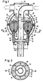
- the fluidized bed apparatus shown has an essentially spherical container 10 and is generally essentially rotationally symmetrical with respect to a vertical container axis 12.
- the container 10 consists of an upper container part 14 and a lower container part 16, each of which has the shape of a spherical shell zone, is essentially made of glass and has flanges 18 and 20 sealingly abutting one another.
- a container attachment 22 adjoins the upper container part 14, while the lower container part 16 merges downwards into a bowl 24.
- Two brackets 26 and 28 are fastened to the container attachment 22 and to the bowl 24, which are clamped together, for example by means of conventional dead center locks or similar quick-release fasteners, which make it possible to quickly disassemble the container parts 14 and 16 for cleaning.
- Either the upper container part 14 remains supported via the container attachment 22 or the lower container part 16 via the bowl 24 on a supporting structure of any type, not shown.
- the container 10 contains powdery or granular material 30 which is mixed or dried or granulated or pelletized or lacquered or coated or subjected to a combination of two or more of these processes.
- the good 30 is shown in FIG. 1 in a fluidized state which occurs during the operation of the apparatus.
- the bowl 24 has an outwardly projecting upper edge 32 which encloses the lower edge of the lower container part 16.
- the nozzles 34 can be designed to spray the material 30 with a liquid, for example a sugar solution; but they can also be designed as solid nozzles for spraying the material 30 or as multi-component nozzles for the simultaneous spraying of liquids and / or solids and / or gases. In any case, the nozzles 34 are staggered at equal angular intervals.
- a cylindrical wall 36 adjoins the upper edge 32 of the bowl 24; this is followed further below by a deflection area which is formed partly by the bowl 24 itself and partly by a closure body 38 which is height-adjustable within the bowl.
- the closure body 38 like the bowl 24, is rotationally symmetrical overall and has an axially upward point.
- the closure body 38 is drawn with solid lines in its operating position, in which it seals the bowl 24 tightly downwards. From this position, the closure body 38 can be raised into an open position, indicated by dashed lines, in which the material 30 can flow down through the bowl 24.
- a dip tube 40 is guided inward in an arc through the container attachment 22, which then extends axially downward in the container 10, ends shortly before the bottom of the bowl 24 and, together with its cylindrical wall 36, delimits a cylindrical annular space 42.
- the outer end of the dip tube 40 can be connected to the pressure side of a blower that conveys air or other gas through the apparatus.
- the blower is not part of the fluidized bed apparatus itself, can be of a conventional design and is therefore not shown.
- annular deflecting screen 44 is attached to the immersion tube 40, the edges of which lie in a common plane, normal to the container axis 12, that is to say horizontal in the example shown, and an annular one each between the immersion tube 40 and the inner wall of the container 10 Clear passages 46 and 48, respectively.
- the two passages 46 and 48 are approximately of the same area, so that in operation approximately the same amount of gas per unit time can flow radially inside and outside past the deflector 44 upwards into the container attachment 22, which can be connected to the suction side of the fan.
- the attachment of the deflector 44 on the immersion tube 40 is adjustable in height, so that the area ratio between the passages 46 and 48 can be changed; the width of the inner passage 46 is independent of the height setting, while the width of the outer passage 48 decreases with increasing height of the deflector screen 44 and vice versa.
- the attachment of the deflector 44 is designed in the example shown with spokes 50 in such a way that the gas flow through the passage 46 is not appreciably obstructed.
- the underside of the deflecting screen 44 is composed of two annular arches 52 and 54, which together form an annular rib 56 projecting downwards.
- the common axis of the two arches 52 and 54 and the rib 56 coincides with the container axis 12.
- the cross-sectional profile of the deflector shield 44 is symmetrical with respect to the rib 56.
- the immersion tube 40 has a constant diameter over almost its entire length, up to approximately a horizontal plane in which the tip of the closure body 38 lies in its closed position. In this plane, the dip tube 40 merges into an edge bead 58.
- the edge bead 58 has an upper section 60 which begins in the equatorial plane of the container 10, there has an outer diameter which corresponds to the outer diameter of the immersion tube 40 and widens in a trumpet shape down to an annular edge 62 which is at the height of the lower edge of the lower container part 16.
- a cylindrical section 64 of the edge bead 58 begins at the edge 62 and delimits the annular space 42 radially inwards.
- the container 10 has its largest free ring cross section in the equatorial plane, in which the flanges 18 and 20 abut one another.
- This largest free ring cross section has an average diameter, which is the arithmetic mean of the largest inner diameter of the container 10 and the outer diameter of the dip tube 40 results.
- the annular space 42 has an average diameter D42, which arises as an arithmetic mean from the inside diameter of the cylindrical wall 36 of the bowl 24 and the outside diameter of the cylindrical section 64 of the edge bead 58 and exactly corresponds to the average diameter of the largest free annular cross section of the container.
- the diameter D56 of the rib 56 is just as large.
- the blower mentioned sucks air or an inert gas in a heated, dry state in the direction of the arrows in FIG. 1 through the apparatus shown, a pressure under ambient pressure being able to prevail in the interior of the container.
- Powdery, solid and liquid substances are sprayed in simultaneously or alternately through the nozzles 34. These substances accumulate on the material 30 before they reach any wall of the apparatus; they therefore have no opportunity to attach themselves to the inner wall of the container 10 or to the dip tube 40 or to the deflector screen 44.
- the apparatus shown is therefore particularly well suited for spraying in substances that are otherwise difficult to process.
Landscapes
- Chemical & Material Sciences (AREA)
- Engineering & Computer Science (AREA)
- Life Sciences & Earth Sciences (AREA)
- Chemical Kinetics & Catalysis (AREA)
- Organic Chemistry (AREA)
- Food Science & Technology (AREA)
- Polymers & Plastics (AREA)
- Health & Medical Sciences (AREA)
- Combustion & Propulsion (AREA)
- General Health & Medical Sciences (AREA)
- Mechanical Engineering (AREA)
- Zoology (AREA)
- Wood Science & Technology (AREA)
- Medicinal Chemistry (AREA)
- Pharmacology & Pharmacy (AREA)
- General Engineering & Computer Science (AREA)
- Public Health (AREA)
- Animal Behavior & Ethology (AREA)
- Veterinary Medicine (AREA)
- Microbiology (AREA)
- Devices And Processes Conducted In The Presence Of Fluids And Solid Particles (AREA)
- Glanulating (AREA)
- Mixers With Rotating Receptacles And Mixers With Vibration Mechanisms (AREA)
- Medical Preparation Storing Or Oral Administration Devices (AREA)
Applications Claiming Priority (2)
| Application Number | Priority Date | Filing Date | Title |
|---|---|---|---|
| DE19853530744 DE3530744A1 (de) | 1985-08-28 | 1985-08-28 | Fliessbettapparatur |
| DE3530744 | 1985-08-28 |
Publications (3)
| Publication Number | Publication Date |
|---|---|
| EP0212397A2 EP0212397A2 (de) | 1987-03-04 |
| EP0212397A3 EP0212397A3 (en) | 1989-05-10 |
| EP0212397B1 true EP0212397B1 (de) | 1990-11-07 |
Family
ID=6279581
Family Applications (1)
| Application Number | Title | Priority Date | Filing Date |
|---|---|---|---|
| EP86110681A Expired - Lifetime EP0212397B1 (de) | 1985-08-28 | 1986-08-01 | Fliessbettapparatur |
Country Status (4)
| Country | Link |
|---|---|
| US (1) | US4736895A (enExample) |
| EP (1) | EP0212397B1 (enExample) |
| JP (1) | JPH0636864B2 (enExample) |
| DE (2) | DE3530744A1 (enExample) |
Families Citing this family (22)
| Publication number | Priority date | Publication date | Assignee | Title |
|---|---|---|---|---|
| GB2211597B (en) * | 1987-10-23 | 1991-11-27 | Torftech Ltd | Processes in which matter is subjected to fluid flow |
| CA1291322C (en) * | 1987-12-17 | 1991-10-29 | John V. Allen | Fluidized bed reactor with two zone combustion |
| EP0321308A1 (en) * | 1987-12-17 | 1989-06-21 | Cet Energy Systems Inc. | Fluidized bed furnace |
| DE3900026C2 (de) * | 1989-01-02 | 1998-02-19 | Rolf Dr Ing Graf | Wirbelkammer |
| DE4118439A1 (de) * | 1991-06-05 | 1992-12-10 | Herbert Huettlin | Fliessbettapparatur zum behandeln partikelfoermigen gutes |
| DE9109008U1 (de) * | 1991-07-22 | 1991-12-12 | Neuhaus Neotec GmbH, 22848 Norderstedt | Vorrichtung zum Mischen von körnigem Gut |
| DE4304405A1 (de) * | 1993-02-15 | 1994-08-18 | Bayer Ag | Verfahren zur kontinuierlichen Wirbelschichtagglomeration |
| US5522555A (en) * | 1994-03-01 | 1996-06-04 | Amherst Process Instruments, Inc. | Dry powder dispersion system |
| US5782010A (en) * | 1995-06-20 | 1998-07-21 | Stork Friesland B.V. | Device for preparing a spray-dried product and method for preparing a product of this kind |
| US6745960B1 (en) * | 1999-06-07 | 2004-06-08 | Freund Industrial Co., Ltd. | Centrifugally rolling granulating device and method of treating powder and granular material using the device |
| US7544250B2 (en) | 2001-10-02 | 2009-06-09 | Huettlin Herbert | Method and apparatus for treating particulate-shaped material, in particular for mixing, drying, graduating, pelletizing and/or coating the material |
| EP1490485B1 (en) | 2002-03-27 | 2015-03-04 | Novozymes A/S | Granules with filamentous coatings |
| AU2003246902A1 (en) * | 2002-08-31 | 2004-03-19 | Axsia Serck Baker Limited | Fluidising apparatus |
| DE10357827A1 (de) * | 2003-12-09 | 2005-07-14 | Glatt Ingenieurtechnik Gmbh | Verfahren zur Herstellung von Enzym-Granulaten und erhältliche Enzym-Granulate |
| CA2528637C (en) | 2003-06-11 | 2012-10-23 | Glatt Ingenieurtechnik Gmbh | Method for production of enzyme granules and enzyme granules produced thus |
| DE10345342A1 (de) * | 2003-09-19 | 2005-04-28 | Engelhard Arzneimittel Gmbh | Verfahren zur Herstellung eines lagerstabilen Extraktes aus Efeublättern, sowie ein nach diesem Verfahren hergestellter Extrakt |
| DE10344845A1 (de) * | 2003-09-26 | 2005-04-14 | Basf Ag | Vorrichtung zum Mischen, Trocknen und Beschichten von pulvrigem, körnigem oder geformtem Schüttgut in einem Fließbett und Verfahren zur Herstellung von Trägerkatalysatoren unter Verwendung einer solchen Vorrichtung |
| DE102004022310B4 (de) * | 2004-05-04 | 2010-01-07 | Daimler Ag | Brennstoffzellensystem mit einem Feuchtigkeitsaustauschmodul mit einem Bündel von für Feuchtigkeit durchlässigen Hohlfasermembranen |
| KR101436409B1 (ko) * | 2013-01-11 | 2014-09-01 | 후성정공 주식회사 | 나노복합소재 제조용 복합 가스 제조장치 |
| JP6173508B1 (ja) * | 2016-03-04 | 2017-08-02 | 三菱日立パワーシステムズ株式会社 | スラグクラッシャ |
| CN106509957B (zh) * | 2016-12-16 | 2018-08-28 | 重庆市奇格食品有限公司 | 一种汤圆搓圆装置 |
| CN112892343A (zh) * | 2018-09-28 | 2021-06-04 | 黄美芬 | 一种芦荟果肉果汁混配罐及其使用方法 |
Family Cites Families (23)
| Publication number | Priority date | Publication date | Assignee | Title |
|---|---|---|---|---|
| DE38538C (de) * | G. BUR-MESTER in Pinneberg | Metalldachplatte | ||
| US1699441A (en) * | 1926-07-05 | 1929-01-15 | Negro Luigi | Apparatus for the treatment of wheat |
| CH264592A (de) * | 1946-09-11 | 1949-10-31 | Vogel Walter Ing Dr | Sammelbehälter mit Pumpanlage zum Mischen und Fördern von unstabilen Trüben, beispielsweise für Schwerflüssigkeitsscheideanlagen. |
| DE872928C (de) * | 1951-09-08 | 1953-04-09 | J K August Lahmann | Vorrichtung zum Umschichten, Auflockern und/oder Mischen von Mehl und sonstigem Schuettgut in Silos u. dgl. Vorratsbehaeltern mittels eines in das Gut hineinversenkten Blasrohr-Systems |
| US2786280A (en) * | 1954-03-12 | 1957-03-26 | Ca Nat Research Council | Method of contacting solid particles with fluids |
| LU39638A1 (enExample) * | 1960-03-02 | 1961-03-11 | ||
| DE1849891U (de) * | 1961-10-12 | 1962-04-12 | Miag Muehlenbau & Ind Gmbh | Behaelter zum mischen von staubgut. |
| US3204942A (en) * | 1963-02-18 | 1965-09-07 | Babcock & Wilcox Co | Distributor for pneumatically transported particle-form material |
| CH412811A (de) * | 1962-11-06 | 1966-05-15 | Ruetschi Ag Pumpenbau K | Verfahren zum Mischen und Einrichtung zur Durchführung des Verfahrens |
| US3411480A (en) * | 1964-01-31 | 1968-11-19 | Smith Kline French Lab | Device for coating fine solids |
| DE1577729A1 (de) * | 1965-04-03 | 1969-09-18 | Hoechst Ag | Beschichtungsanlage zum UEberziehen von Kernen |
| DE1507890A1 (de) * | 1965-09-18 | 1969-04-03 | Bayer Ag | Verfahren und Vorrichtung zum pneumatischen Mischen,Trocknen oder Befeuchten von pulverfoermigem Gut |
| DE1297447B (de) * | 1966-06-08 | 1969-06-12 | Neumayer Josef | Mischvorrichtung fuer pulverfoermige, faserige oder koernige Schuettgueter |
| DE1632404A1 (de) * | 1968-02-14 | 1970-08-13 | Miag Muehlenbau & Ind Gmbh | Pneumatische Mischvorrichtung |
| FR2299903A1 (fr) * | 1975-02-07 | 1976-09-03 | Vansteene Jean | Saturateur en gaz de couches liquides profondes |
| US4050406A (en) * | 1976-02-05 | 1977-09-27 | Reni-Cirillo S.R.L. | Coating machine for confectionery, pharmaceuticals and similar products |
| US4002325A (en) * | 1976-03-22 | 1977-01-11 | Herfeld Friedrich W | Apparatus for mixing powdery or granulated materials |
| US4168914A (en) * | 1977-06-06 | 1979-09-25 | General Electric Company | Method and apparatus for blending fine and cohesive powders in a fluidized bed with gas injection through ball valves |
| IE49127B1 (en) * | 1979-01-08 | 1985-08-07 | Bpb Industries Ltd | Calcination method and apparatus |
| US4217851A (en) * | 1979-08-27 | 1980-08-19 | American Cyanamid Company | Tablet coating apparatus |
| US4425865A (en) * | 1980-11-17 | 1984-01-17 | Saat- Und Erntetechnik Gmbh | Method for the homogeneous complete encapsulation of individual grains of pourable material and apparatus for its production |
| US4466082A (en) * | 1982-02-02 | 1984-08-14 | Foster Wheeler Energy Corporation | Apparatus for mixing and distributing solid particulate material |
| DE3234911A1 (de) * | 1982-09-21 | 1984-03-22 | Herbert 7853 Steinen Hüttlin | Fliessbettapparatur |
-
1985
- 1985-08-28 DE DE19853530744 patent/DE3530744A1/de active Granted
-
1986
- 1986-08-01 DE DE8686110681T patent/DE3675459D1/de not_active Expired - Lifetime
- 1986-08-01 EP EP86110681A patent/EP0212397B1/de not_active Expired - Lifetime
- 1986-08-08 US US06/894,802 patent/US4736895A/en not_active Expired - Lifetime
- 1986-08-25 JP JP61197450A patent/JPH0636864B2/ja not_active Expired - Lifetime
Also Published As
| Publication number | Publication date |
|---|---|
| DE3530744C2 (enExample) | 1989-02-23 |
| EP0212397A2 (de) | 1987-03-04 |
| DE3675459D1 (de) | 1990-12-13 |
| EP0212397A3 (en) | 1989-05-10 |
| DE3530744A1 (de) | 1987-03-05 |
| US4736895A (en) | 1988-04-12 |
| JPS6253732A (ja) | 1987-03-09 |
| JPH0636864B2 (ja) | 1994-05-18 |
Similar Documents
| Publication | Publication Date | Title |
|---|---|---|
| EP0212397B1 (de) | Fliessbettapparatur | |
| EP0103894B1 (de) | Fliessbettapparatur | |
| DE4006935C2 (enExample) | ||
| DE3839723C1 (enExample) | ||
| CH670960A5 (enExample) | ||
| DE19709589C2 (de) | Fließbettapparatur zum Behandeln von partikelförmigem Gut | |
| EP1232003A2 (de) | Vorrichtung zum beschichten von partikeln | |
| EP0541759B1 (de) | Fliessbettapparatur zum behandeln partikelförmigen gutes | |
| EP0172530B1 (de) | Fliessbettapparatur | |
| DE2506222A1 (de) | Vorrichtung zum ueberziehen von tabletten oder anderem gut | |
| DE19549533C2 (de) | Sprühbeschichtungsvorrichtung | |
| EP0331112B1 (de) | Wirbelschichtapparatur, insbes. zum Granulieren pulverförmiger Substanz | |
| EP0211343B1 (de) | Vorrichtung zum Behandeln von Substanzen in einem Gasstrom | |
| DE3806539A1 (de) | Wirbelschichtapparatur, insbes. zum granulieren pulverfoermiger substanz | |
| DE3520718A1 (de) | Fliessbettapparatur | |
| DE3523990A1 (de) | Fliessbettapparatur | |
| WO2005092485A2 (de) | Verfahren und vorrichtung zum pneumatischen behandeln pulverförmiger stoffe | |
| DE10024991B4 (de) | Mischerprozessor | |
| AT392015B (de) | Ruehrvorrichtung fuer wirbelschichten mit klassierendem abzug | |
| DE8424663U1 (de) | Fließbettapparatur | |
| DE202012102157U1 (de) | Wirbelschichtgerät mit konischem Fluidboden | |
| CH686408A5 (de) | Fliessbettapparatur zum Behandeln partikelfoermigen Gutes. | |
| DE10149764A1 (de) | Verfahren und Vorrichtung zum Behandeln partikelförmigen Guts, insbesondere zum Mischen, Trocknen, Granulieren, Pelletieren und/oder Coaten des Guts | |
| DE1143791B (de) | Misch- und Ruehrwerk fuer ruhende Behaelter, insbesondere fuer Hochdruck-Autoklaven | |
| DE19648142A1 (de) | Wirbelboden für Wirbelschichtapparate |
Legal Events
| Date | Code | Title | Description |
|---|---|---|---|
| PUAI | Public reference made under article 153(3) epc to a published international application that has entered the european phase |
Free format text: ORIGINAL CODE: 0009012 |
|
| AK | Designated contracting states |
Kind code of ref document: A2 Designated state(s): CH DE GB LI NL SE |
|
| PUAL | Search report despatched |
Free format text: ORIGINAL CODE: 0009013 |
|
| AK | Designated contracting states |
Kind code of ref document: A3 Designated state(s): CH DE GB LI NL SE |
|
| 17P | Request for examination filed |
Effective date: 19890418 |
|
| 17Q | First examination report despatched |
Effective date: 19891219 |
|
| GRAA | (expected) grant |
Free format text: ORIGINAL CODE: 0009210 |
|
| AK | Designated contracting states |
Kind code of ref document: B1 Designated state(s): CH DE GB LI NL SE |
|
| GBT | Gb: translation of ep patent filed (gb section 77(6)(a)/1977) | ||
| REF | Corresponds to: |
Ref document number: 3675459 Country of ref document: DE Date of ref document: 19901213 |
|
| PLBE | No opposition filed within time limit |
Free format text: ORIGINAL CODE: 0009261 |
|
| STAA | Information on the status of an ep patent application or granted ep patent |
Free format text: STATUS: NO OPPOSITION FILED WITHIN TIME LIMIT |
|
| 26N | No opposition filed | ||
| PGFP | Annual fee paid to national office [announced via postgrant information from national office to epo] |
Ref country code: NL Payment date: 19940831 Year of fee payment: 9 |
|
| EAL | Se: european patent in force in sweden |
Ref document number: 86110681.3 |
|
| PG25 | Lapsed in a contracting state [announced via postgrant information from national office to epo] |
Ref country code: NL Effective date: 19960301 |
|
| NLV4 | Nl: lapsed or anulled due to non-payment of the annual fee |
Effective date: 19960301 |
|
| PGFP | Annual fee paid to national office [announced via postgrant information from national office to epo] |
Ref country code: SE Payment date: 19960718 Year of fee payment: 11 |
|
| PG25 | Lapsed in a contracting state [announced via postgrant information from national office to epo] |
Ref country code: SE Free format text: LAPSE BECAUSE OF NON-PAYMENT OF DUE FEES Effective date: 19970802 |
|
| EUG | Se: european patent has lapsed |
Ref document number: 86110681.3 |
|
| PGFP | Annual fee paid to national office [announced via postgrant information from national office to epo] |
Ref country code: GB Payment date: 20010713 Year of fee payment: 16 |
|
| PGFP | Annual fee paid to national office [announced via postgrant information from national office to epo] |
Ref country code: CH Payment date: 20010716 Year of fee payment: 16 |
|
| PGFP | Annual fee paid to national office [announced via postgrant information from national office to epo] |
Ref country code: DE Payment date: 20010926 Year of fee payment: 16 |
|
| REG | Reference to a national code |
Ref country code: GB Ref legal event code: IF02 |
|
| PG25 | Lapsed in a contracting state [announced via postgrant information from national office to epo] |
Ref country code: GB Free format text: LAPSE BECAUSE OF NON-PAYMENT OF DUE FEES Effective date: 20020801 |
|
| PG25 | Lapsed in a contracting state [announced via postgrant information from national office to epo] |
Ref country code: LI Free format text: LAPSE BECAUSE OF NON-PAYMENT OF DUE FEES Effective date: 20020831 Ref country code: CH Free format text: LAPSE BECAUSE OF NON-PAYMENT OF DUE FEES Effective date: 20020831 |
|
| PG25 | Lapsed in a contracting state [announced via postgrant information from national office to epo] |
Ref country code: DE Free format text: LAPSE BECAUSE OF NON-PAYMENT OF DUE FEES Effective date: 20030301 |
|
| GBPC | Gb: european patent ceased through non-payment of renewal fee |
Effective date: 20020801 |
|
| REG | Reference to a national code |
Ref country code: CH Ref legal event code: PL |