EP0212349A1 - Transporteur pour copeaux - Google Patents
Transporteur pour copeaux Download PDFInfo
- Publication number
- EP0212349A1 EP0212349A1 EP86110349A EP86110349A EP0212349A1 EP 0212349 A1 EP0212349 A1 EP 0212349A1 EP 86110349 A EP86110349 A EP 86110349A EP 86110349 A EP86110349 A EP 86110349A EP 0212349 A1 EP0212349 A1 EP 0212349A1
- Authority
- EP
- European Patent Office
- Prior art keywords
- web
- nut
- saddle
- chip conveyor
- slot
- Prior art date
- Legal status (The legal status is an assumption and is not a legal conclusion. Google has not performed a legal analysis and makes no representation as to the accuracy of the status listed.)
- Withdrawn
Links
- 239000000463 material Substances 0.000 claims description 9
- 230000000149 penetrating effect Effects 0.000 claims description 2
- 238000004519 manufacturing process Methods 0.000 description 3
- 238000005516 engineering process Methods 0.000 description 2
- 230000002349 favourable effect Effects 0.000 description 2
- 229910001060 Gray iron Inorganic materials 0.000 description 1
- 229910000639 Spring steel Inorganic materials 0.000 description 1
- 238000005452 bending Methods 0.000 description 1
- 230000003292 diminished effect Effects 0.000 description 1
- 230000000694 effects Effects 0.000 description 1
- 239000002184 metal Substances 0.000 description 1
- 229910052751 metal Inorganic materials 0.000 description 1
- 230000000284 resting effect Effects 0.000 description 1
- 230000008719 thickening Effects 0.000 description 1
Images

Classifications
-
- B—PERFORMING OPERATIONS; TRANSPORTING
- B65—CONVEYING; PACKING; STORING; HANDLING THIN OR FILAMENTARY MATERIAL
- B65G—TRANSPORT OR STORAGE DEVICES, e.g. CONVEYORS FOR LOADING OR TIPPING, SHOP CONVEYOR SYSTEMS OR PNEUMATIC TUBE CONVEYORS
- B65G25/00—Conveyors comprising a cyclically-moving, e.g. reciprocating, carrier or impeller which is disengaged from the load during the return part of its movement
- B65G25/04—Conveyors comprising a cyclically-moving, e.g. reciprocating, carrier or impeller which is disengaged from the load during the return part of its movement the carrier or impeller having identical forward and return paths of movement, e.g. reciprocating conveyors
- B65G25/08—Conveyors comprising a cyclically-moving, e.g. reciprocating, carrier or impeller which is disengaged from the load during the return part of its movement the carrier or impeller having identical forward and return paths of movement, e.g. reciprocating conveyors having impellers, e.g. pushers
Definitions
- slotted bottom is designed in the shape of a saddle and the upper edge of the web runs correspondingly in the shape of a saddle over the length of the nut.
- the nut protrudes into the region of an edge-side recess in the upper edge of the web, the base line of which is aligned with the course of the saddle. No additional material then needs to be attached to the web.
- the recess can be produced in a simple manner by notching the web on the edge, the base line simultaneously receiving its saddle course. As mentioned above, this can be designed in an arc shape. However, a roof-shaped saddle is also conceivable, to which the saddle course of the slot of the nut would then have to be adjusted.
- the web is the leg of an angular profile, the other leg of which rests on the conveyor trough bottom and a floor wear plate extends from the lower longitudinal flank of the web.
- the base wear plate is preferably not yet attached in the manufacture of the notches forming the cutouts. This makes the angle profile easier to handle.
- this embodiment proves to be very stable in use, since the web is made of the same material from the one leg resting on the conveyor trough bottom, which also serves as a wear plate.
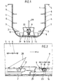
- the chip conveyor has a conveyor trough 1 with a U-shaped cross section.
- the horizontal U-web forms the trough bottom 2, which merges into the trough side walls 4 via inclined intermediate sections 3. At the upper end, these are provided with outwardly directed bends 5 lying horizontally.
- the conveyor trough designed in this way can be sunk into a channel as a whole, the bends 5 being able to terminate with the upper edge thereof.
- Barbs 6 are attached to the inner wall of the channel side walls 4 at different heights. Furthermore, there are barbs 7, 8 on the inside of the intermediate sections 3. All barbs 6 to 8 serve to hold back the chips located in the conveyor trough 1 when a push rod 9 moves back.
- the recesses 17 serve to receive nuts 20, which represent the support for the push rod 9.
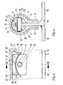
- the outer diameter of the nut 20 is smaller than the inner diameter of the cylindrical section 10 of the push rod 9. Accordingly, the push rod 9, encompassing the nut 20, sits with lateral play on the web 13.
- Each nut 20 is provided with a slot 21 on its underside, the width of which corresponds to the thickness of the web 13.
- the slot floor 21 is designed saddle-shaped such that there is an arcuate saddle course.
- the nut has the smallest wall thickness in the area of the saddle apex S 1. This course of the saddle is adapted to the course of the base line 19 of the recess 17. In this way it is achieved that the end regions 22 of the nut have approximately twice the wall thickness compared to the region of the saddle apex S1.
- a cross pin 23 is used, which passes through both aligned holes 24 of the wall sections 25 located on the side of the slot 21 and a hole 26 in the web 23, which hole is located below the apex S of the base line 19 the recess 17 extends.
- the holes 24 in the nut 20 are arranged offset eccentrically in the nut 20.
- the end faces 23 'of the cross pin 23 are crowned.
- the cross pin 23 is inserted into the holes 24, 26 in a sliding fit. Since the play of the push rod 9 on the nuts 20 is less than the material thickness of the wall sections 25, the cross pin 23 can not move from its position securing the nut despite its displaceability.
- a gap 27 is present between the saddle-shaped edge (base line 19) and slot bottom 21.
- the dimension of the gap is smaller than towards the edge.
- the edge flanks 18 are at a distance from the front ends of the nut. otherwise there is such a distance y between the upper track line of the nut 20 and the upper edge 13 'of the web, which is greater than the wall thickness of the nut in the region of the saddle apex S1.
- the wall thickness 8-9 mm, so a distance of 12-14 mm is recommended with the usual dimensions.
- the service life of the nut is considerably increased, however, since the corresponding end region 22 has the greatest material thickness in the slot plane there.
- the cross sections of rod and / or nut can also be different than round, e.g. B. upright corner profiles (box or angle).
Landscapes
- Engineering & Computer Science (AREA)
- Mechanical Engineering (AREA)
- Screw Conveyors (AREA)
- Chain Conveyers (AREA)
Applications Claiming Priority (2)
| Application Number | Priority Date | Filing Date | Title |
|---|---|---|---|
| DE19853529362 DE3529362A1 (de) | 1985-08-16 | 1985-08-16 | Spaenefoerderer |
| DE3529362 | 1985-08-16 |
Publications (1)
| Publication Number | Publication Date |
|---|---|
| EP0212349A1 true EP0212349A1 (fr) | 1987-03-04 |
Family
ID=6278644
Family Applications (1)
| Application Number | Title | Priority Date | Filing Date |
|---|---|---|---|
| EP86110349A Withdrawn EP0212349A1 (fr) | 1985-08-16 | 1986-07-26 | Transporteur pour copeaux |
Country Status (2)
| Country | Link |
|---|---|
| EP (1) | EP0212349A1 (fr) |
| DE (1) | DE3529362A1 (fr) |
Citations (3)
| Publication number | Priority date | Publication date | Assignee | Title |
|---|---|---|---|---|
| US3777880A (en) * | 1972-04-13 | 1973-12-11 | Kalamazoo Conveyor Co | Plow harpoon-type conveyor |
| DE1931549B2 (de) * | 1969-06-21 | 1978-03-09 | Koebo Koehler & Bovenkamp Gmbh, 5600 Wuppertal | Förderer, insbesondere für Späne |
| DE3402986A1 (de) * | 1984-01-28 | 1985-08-01 | "KÖBO" Köhler & Bovenkamp GmbH, 5600 Wuppertal | Spaenefoerderer |
-
1985
- 1985-08-16 DE DE19853529362 patent/DE3529362A1/de not_active Withdrawn
-
1986
- 1986-07-26 EP EP86110349A patent/EP0212349A1/fr not_active Withdrawn
Patent Citations (3)
| Publication number | Priority date | Publication date | Assignee | Title |
|---|---|---|---|---|
| DE1931549B2 (de) * | 1969-06-21 | 1978-03-09 | Koebo Koehler & Bovenkamp Gmbh, 5600 Wuppertal | Förderer, insbesondere für Späne |
| US3777880A (en) * | 1972-04-13 | 1973-12-11 | Kalamazoo Conveyor Co | Plow harpoon-type conveyor |
| DE3402986A1 (de) * | 1984-01-28 | 1985-08-01 | "KÖBO" Köhler & Bovenkamp GmbH, 5600 Wuppertal | Spaenefoerderer |
Also Published As
| Publication number | Publication date |
|---|---|
| DE3529362A1 (de) | 1987-02-19 |
Similar Documents
| Publication | Publication Date | Title |
|---|---|---|
| DE2515022A1 (de) | Bauelementensatz zur herstellung von variablen traggeruesten | |
| DE3805918A1 (de) | Rahmen fuer bandfoerdervorrichtungen | |
| DE3423504A1 (de) | Befestigungsvorrichtung | |
| DE2220092A1 (de) | Bauelementensatz zur herstellung von variablen traggeruesten | |
| DE3828469A1 (de) | Legebarrenlagerung fuer kettenwirkmaschinen | |
| DE7719231U1 (de) | Metallgitterrost | |
| EP0112464B1 (fr) | Dispositif tendeur pour fonds racleurs ou fonds transporteurs analogues sur véhicules ou engins agricoles | |
| DE3408282C2 (fr) | ||
| DE3628179C2 (fr) | ||
| DE2403978A1 (de) | Foerdereinrichtung fuer metallabfaelle | |
| CH624174A5 (en) | Adjustable suspension for doors. | |
| EP0212349A1 (fr) | Transporteur pour copeaux | |
| EP1384693B1 (fr) | Rampe hélicoidale | |
| DE4025871A1 (de) | Hobelfuehrung fuer gewinnungshobel | |
| DE3035604C2 (fr) | ||
| DE3200498C2 (fr) | ||
| DE8912144U1 (de) | Standregal | |
| CH676230A5 (en) | Conveyor belt requiring few rollers | |
| DE19925559C1 (de) | Kette für Spannrahmentrockner | |
| DE3035620C2 (fr) | ||
| DE3934060C1 (en) | Modular shelf and stand assembly - has uprights on supporting feet consisting of L=shaped bars bolted together to form T- or cruciform cross=sections | |
| DE3628566C2 (fr) | ||
| CH670749A5 (en) | Cabinet and/or table mounted on vertical wall | |
| DE3628553C2 (fr) | ||
| DE1286489B (de) | Foerderer, insbesondere Kratzerfoerderer als Strebfoerderer mit kurzen Zwischenrinnenschuessen zur Befestigung von Aufsatzblechen od. dgl. |
Legal Events
| Date | Code | Title | Description |
|---|---|---|---|
| PUAI | Public reference made under article 153(3) epc to a published international application that has entered the european phase |
Free format text: ORIGINAL CODE: 0009012 |
|
| AK | Designated contracting states |
Kind code of ref document: A1 Designated state(s): AT BE CH DE FR GB IT LI LU NL SE |
|
| STAA | Information on the status of an ep patent application or granted ep patent |
Free format text: STATUS: THE APPLICATION IS DEEMED TO BE WITHDRAWN |
|
| 18D | Application deemed to be withdrawn |
Effective date: 19870905 |
|
| RIN1 | Information on inventor provided before grant (corrected) |
Inventor name: SCHEMANN, RAINER |