EP0210071A2 - Lamelle pour microscope - Google Patents
Lamelle pour microscope Download PDFInfo
- Publication number
- EP0210071A2 EP0210071A2 EP86305615A EP86305615A EP0210071A2 EP 0210071 A2 EP0210071 A2 EP 0210071A2 EP 86305615 A EP86305615 A EP 86305615A EP 86305615 A EP86305615 A EP 86305615A EP 0210071 A2 EP0210071 A2 EP 0210071A2
- Authority
- EP
- European Patent Office
- Prior art keywords
- examination chamber
- examination
- base plate
- cover plate
- chamber roof
- Prior art date
- Legal status (The legal status is an assumption and is not a legal conclusion. Google has not performed a legal analysis and makes no representation as to the accuracy of the status listed.)
- Granted
Links
- 238000007689 inspection Methods 0.000 title abstract description 19
- 239000007788 liquid Substances 0.000 claims description 15
- 229920003023 plastic Polymers 0.000 claims description 6
- 239000012530 fluid Substances 0.000 abstract description 39
- 239000007789 gas Substances 0.000 abstract description 7
- 230000003287 optical effect Effects 0.000 description 14
- 239000013618 particulate matter Substances 0.000 description 8
- 238000001704 evaporation Methods 0.000 description 4
- 230000008020 evaporation Effects 0.000 description 4
- 238000000034 method Methods 0.000 description 4
- 229920002972 Acrylic fiber Polymers 0.000 description 2
- 208000003464 asthenopia Diseases 0.000 description 2
- 239000013060 biological fluid Substances 0.000 description 2
- 238000009826 distribution Methods 0.000 description 2
- 239000011521 glass Substances 0.000 description 2
- 239000002253 acid Substances 0.000 description 1
- 238000004458 analytical method Methods 0.000 description 1
- 238000013459 approach Methods 0.000 description 1
- 230000000712 assembly Effects 0.000 description 1
- 238000000429 assembly Methods 0.000 description 1
- 230000000740 bleeding effect Effects 0.000 description 1
- 239000008280 blood Substances 0.000 description 1
- 210000004369 blood Anatomy 0.000 description 1
- 238000004113 cell culture Methods 0.000 description 1
- 238000011109 contamination Methods 0.000 description 1
- 230000003247 decreasing effect Effects 0.000 description 1
- 230000007812 deficiency Effects 0.000 description 1
- 230000000593 degrading effect Effects 0.000 description 1
- 230000000694 effects Effects 0.000 description 1
- 238000001746 injection moulding Methods 0.000 description 1
- 238000002955 isolation Methods 0.000 description 1
- 238000004519 manufacturing process Methods 0.000 description 1
- 238000013508 migration Methods 0.000 description 1
- 230000005012 migration Effects 0.000 description 1
- 238000000465 moulding Methods 0.000 description 1
- 239000011236 particulate material Substances 0.000 description 1
- 238000002360 preparation method Methods 0.000 description 1
- 230000000717 retained effect Effects 0.000 description 1
- 238000003860 storage Methods 0.000 description 1
- 210000002700 urine Anatomy 0.000 description 1
- 238000003466 welding Methods 0.000 description 1
Images


Classifications
-
- G—PHYSICS
- G02—OPTICS
- G02B—OPTICAL ELEMENTS, SYSTEMS OR APPARATUS
- G02B21/00—Microscopes
- G02B21/34—Microscope slides, e.g. mounting specimens on microscope slides
Definitions
- Laboratory analysis of biological fluids such as blood, spinal fluid, cell cultures and urine can include microscopic examination of a specimen liquid to determine the presence or concentration of suspended particulate matter such as cells.
- microscopic examination of liquid specimens has been accomplished by placing a drop of the specimen liquid on a flat transparent microscope slide and then placing a thin flat transparent coverslip over the specimen. The weight of the coverslip and the inherent capillation between the liquid specimen the microscope slide and the coverslip presses the coverslip against the slide and distributes the liquid as a film in the space between the slide and the coverslip. The slide is then placed on a microscope stage and the liquid specimen between the slide and the coverslip is examined.
- the thickness of each specimen must be essentially equal or again must be known so that calculations of volumes in which the particulate species are suspended can be made. Assumptions regarding the thickness of liquid specimens are not useful because uncontrollable variables such as variations in the surface tension from sample to sample which substantially effects thickness, variations in the amount of liquid used for.preparing slide specimens, entrapment of air between the slide and coverslip and variations in the pressure exerted between the coverslip and the slide all cause differences in specimen thickness.
- degrading the utility of such micrcscopic counts are perturbations in the distribution of particulates in specimens caused by inadvertent translational movement of coverslips with respect to slides during preparation of slide/coverslip assemblies which can result in non-uniformity cf the distribution of particulates in specimens.
- the depth of examination chambers should be maintained within the depth of field of instruments used to examine specimens.
- the depth of the examination chamber with respect to the microscope should be maintained at 0.004 inches which is equal to or less than one focal plane of optical instruments used for this type of laboratory work.
- the present invention which provides inspection slides, with fixed coverslips, having examination chambers with constant depths that can be maintained shorter than the depth of field for inspecting optical instruments and also has examination chambers from which entraped gases can be readily bleed, and from which excess specimen fluids can be readily drained.
- the examination chamber roofs which are recessed, have smaller surface areas than the examination chamber floor surfaces, and surrounding the examination chamber roofs are depth control ridges spaced a uniform distance from the examination chamber roof surfaces. Additionally the depth control ridges extend beyond the outer edge of the examination chamber floor surfaces when a cover plate and base plate are assembled. Therefore the examination chamber roofs are displaced from the examination chamber floors by distances determined by the depth control ridges.
- each depth control ridge In combination with the examination chamber floor and roof surfaces, and the depth control ridges are at least one notch cut into each depth control ridge which extends from outside the areas defined by the examination chamber floor surfaces and then over each examination chamber floor surface to the examination roof surface. These notches provide channels for bleeding entraped gases from the examination chambers and for draining excess specimen fluids from the examination chambers.
- Each of the examination chambers on an inspection slide of the present invention has an opening facing an edge of the base plate. These openings are formed by a ramp surface intersecting each examination chamber floor surface and by the examination chamber roof positioned above the intersection of the examination chamber floor and the ramp surface.
- This configuration of ramp surface and examination chamber roof permits efficient charging of the examination chamber with specimen fluid. Such charging can be accomplished by a pipette or dropper positioned at the opening to introduce a drop of specimen fluid, the specimen fluid will wet both the examination chamber roof and floor.
- the wetted examination chamber roof and floor guides the specimen in to fill the examination chamber by capillation. During the filling of an examination chamber entraped gases are bleed
- An inspection slide according to the present invention is assembled by placing a cover plate fabricated from transparent plastic and having at least one coverslip portion on top of a base plate also fabricated from transparent plastic and having at least one examination chamber floor which is a flat and optically smooth surface.
- the coverslip portion of the cover plate is positioned so that it essentially overlays the examination chamber floor. This configuration is then maintained by bonding the cover plate to the base plate.
- the bonds between the base plate and the cover plate are made at locations remote from the examination chamber so that dimensional distortions inevitably associated with bonding plastic structures are minimized by the distances between the bonding points and the examination chambers.
- Examination chambers in the inspection slide of the present invention are formed from the abutting contact of the coverslip portior. of a cover plate onto the examination chamber floor surface defined on a base plate.
- the abutting contact is maintained by bonding portions of the cover plate to the base plate.
- a second function provided by the bonded portions of the cover plate and base plate besides maintaining contact between these two plates is the isolation of examination chambers so that a liquid specimen which drains from one examination chamber will not migrate to a second examination chamber and contaminate a second specimen.
- the examination chamber floor surfaces on a base plate are flat optically smooth surfaces which are raised above a main base plate surface, and the coverslip portions of a cover plate include examination chamber roofs which are also flat and optically smooth surfaces but are recessed into the cover plate and are of a similar general shape as the examination chamber floor surfaces.
- the examination chamber roofs through the notches in the depth control ridge and after filling of an examination chamber excess specimen fluid is drained through the same notch. Capillation in addition to providing a mechanism for filling examination chambers with specimen fluids also maintains a constant depth between the examination chamber roofs and floors by attracting the roofs toward the floors to distances determined by the depth control ridges through the medium of the specimen fluids.
- the examination chamber roof can be configured to overhang the ramp surface of the present invention in one embodiment and to include a lip which extends from the examination chamber roof to the ramp surface where it is bonded to the ramp so as to reduce the area cf the opening and thus decrease evaporation rates for specimen fluids. This lip extends along approximately seventy percent of the length of the examination chamber roof edge adjacent the opening used to charge the examination chamber but does not extend to the ends of the opening.
- a drop of specimen fluid can be placed for charging the examination chamber. Because the lip from the examination chamber roof will provide a guiding surface the specimen fluid will first be drawn along the length of the lip and then will be drawn into the examination chamber. In accordance with the present invention the lip is positioned over the ramp surface so that a volume of specimen fluid is positioned in front of the examination chamber. This volume of fluid must be evaporated before that in the examination chamber can be evaporated.
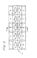
- Inspection slide 10 includes cover plate 12 and base plate 14.
- a top plan view of an assembled inspection slide 10 as shown in FIG. 1 is shown in FIG. 2.
- the base plate 14 for an inspection slide 10 includes examination chamber floor surfaces 16 which are flat optically smooth surfaces.
- one or more examination chamber floor surfaces 16 can be oriented on a base plate 14.
- the examination chamber floor surfaces 16 are oriented on the base plate 14 so that the examination chamber floor surface 16 is parallel to the bottom surface 18 of the base plate 14. Having the examination chamber floor surface 16 parallel to the bottom surface 18 of the base plate 14 assures that when the base plate 14 is positioned on the stage of an optical instrument having its optical axes perpendicular to the stage the examination chamber floor surface 16 will also be perpendicular to the optical axis of the instrument.
- the examination chamber floor surfaces 16 are also raised above an upper deck 20 of the base plate 14.
- Cover plate 12 has recessed below a lower surface 22 examination chamber roofs 24, which like the examination chamber floor surfaces 16 are flat and optically smooth surfaces.
- the examination chamber roofs 24 have surface areas which are generally the same shape as those of the examination chamber floors surfaces 16 but the examination chamber roofs 24 have shorter linear dimensions, L and W (See FIG 1).
- Surrounding the examination chamber roofs 24 are depth ccntrol ridges 26 which are also recessed below the lower surface 22 of the cover plate 12.
- the depth control ridges 26 are not recessed as deep as the examination chamber roofs 24, but the depth control ridges 26 do extend from the examination charter roofs 24 out to locations beyond the surface areas of the examination chamber floor surfaces 16. Therefore, the cover plates 12 can be positioned on the base plates 14 so that the examination chamber roofs 24 are supported via the depth control ridges 26 at constant distances determined by the depth control ridges 26 from the examination chamber floor surfaces 16.
- the depth control ridges 26 extend from the examination chamber roof 24 on all sides except one. That side being where the examination chamber 28 is charged with specimen fluid.
- the depth control ridges 26 are preferably maintained so as to have the examination chamber roofs 24 recessed 0.0045 inches + 0.0005 inches from the bottom of the depth control ridges 26.
- the present invention can also be used for special applications such as hemacytometry which previously required accurately ground and polished glass slide/coverslip combinations.
- a counting grid is etched on the chamber roofs 24 using known techniques, and the depth control ridges 26 are preferably maintained so as to have the examination chamber roofs 24 recessed 0.010 inches + 0.001 inches from the bottom of the depth control ridges 26.
- the energy directing ridges 30 are located between examination chamber floor surfaces 16.
- Such positioning of the cover plate 12 with respect to the base plate 14 is assured by tabs 32 located between the examination chamber floor surfaces 16, at the edges of the base plate 14 and raised above the examination chamber floor surfaces 16 a distance essentially equal to the thickness, of the cover plate 12.
- the tabs 32 between the examination chamber floor surfaces 16 assure proper positioning of the cover plate 12 in the dimension between the tabs 32 with respect to the base plate 14 while the energy directing ridges 30 which extend from the lower surface 22 of the cover plat ⁇ 12 and which are essentially dimensioned to fit between and in close proximity to the supports 34 for the examination chamber floor surfaces 16 assure proper positioning of the cover plate 12 in the dimension perpendicular to that defined by tabs 32.
- the energy directing ridges 30 are ultrasonically welded to the base plate 14 using techniques known in the art.
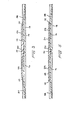
- each examination chamber 28 there is a ramp surface 38 extending up from an outer edge of the base plate 14 to the examination chamber floor surface 16 and intersecting the examination chamber floor surface 16 along a line just under the examination chamber roof 24.
- the opening between the examination chamber floor surface 16 and the examination chamber roof 24 defined along the line where the ramp 38 and examination chamber floor surface 16 intersect provides a gate for charging the examination chamber 28 with a specimen fluid. Capillation draws a fluid which is positioned on the ramp 38 at the edge of examination chamber roof 24 into the examination chamber 28.
- the cover plate 12 is recessed back so that the edge of the examination chamber roof 24 is positioned essentially directly above the intersection of the examination chamber floor surface 16 and ramp surface 38 (see FIGS. 4 and 5 ).
- These recesses provide charging ports 40 where a drop of specimen fluid can be positioned and taken by capillation into the examination chambers 28.
- Another feature of this embodiment is the extension of the examination roof 24 beyond the intersection of the examination chamber floor surface 16 and the ramp 38 along the section between charging ports 40, and the provision of a lip ridge 42 along the length of the examination chamber roof 24 which approaches the surface of the ramp 38 where it is ultrasonically welded when cover plate 12 is welded to base plate 14. A volume having a triangular cross sectional area is then defined between lip ridge 42, examination chamber roof 24 and ramp 38. Placing a drop of specimen fluid at a charging port 40 will result in the fluid being drawn by capillation along the length of the lip ridge 42 because the depth from the examination chamber roof 24 to the ramp 38 is greater than the distance between the examination chamber roof 24 to the exmination chamber floor surface 16.
- the specimen fluid After filling the volume along the length of the lip ridge 42 the specimen fluid will evenly fill the examination chamber from the opening back.
- a reservoir is effectively formed behind the lip ridge 42. Evaporation of the specimen fluid in the examination chamber 28 can not begin until the fluid in the reservoir is first evaporated.
- the reservoir additionally provides for contained storage of specimen fluid to prevent contamination of optics by careless use of the inspecting instrument.
- notches 44 which are cut out to the outer edges of the depth control ridges 26 so that both entraped gases and excess fluid can be drained from the examination chambers 28 to ensure complete filling of the examination chamber with specimen fluid.
- the notches 44 extend from between the examination chamber roof 24 and floor 16 out beyond the edge of the examination chamber floor surface 16 so both gases and fluids can easily be drained from the examination chamber 28.
- the volumes of the openings provided by the notches 44 are sized so as not to provide preferential capillation for draining specimen fluid from the examination chamber.
- Inspection plates 10 of the present invention may be fabricated from acrylic plastic by injection molding the cover plate 12 and base plate 14 and then ultrasonically welding them together.
- the acrylic plastic should have an index of refraction essentially equal to glass and should be of a grade which is wettable and free from acid affinity.
- the examination chamber roof 24 and floor 16 surfaces can be formed by use of mold surfaces which are polished optically flat.
Landscapes
- Physics & Mathematics (AREA)
- Chemical & Material Sciences (AREA)
- Analytical Chemistry (AREA)
- General Physics & Mathematics (AREA)
- Optics & Photonics (AREA)
- Sampling And Sample Adjustment (AREA)
- Microscoopes, Condenser (AREA)
Applications Claiming Priority (2)
| Application Number | Priority Date | Filing Date | Title |
|---|---|---|---|
| US06/758,056 US4637693A (en) | 1985-07-23 | 1985-07-23 | Microscope inspection slide |
| US758056 | 1985-07-23 |
Publications (3)
| Publication Number | Publication Date |
|---|---|
| EP0210071A2 true EP0210071A2 (fr) | 1987-01-28 |
| EP0210071A3 EP0210071A3 (fr) | 1988-09-07 |
| EP0210071B1 EP0210071B1 (fr) | 1998-09-30 |
Family
ID=25050314
Family Applications (1)
| Application Number | Title | Priority Date | Filing Date |
|---|---|---|---|
| EP86305615A Expired - Lifetime EP0210071B1 (fr) | 1985-07-23 | 1986-07-22 | Lamelle pour microscope |
Country Status (4)
| Country | Link |
|---|---|
| US (1) | US4637693A (fr) |
| EP (1) | EP0210071B1 (fr) |
| JP (1) | JPH0697307B2 (fr) |
| DE (1) | DE3650701T2 (fr) |
Cited By (7)
| Publication number | Priority date | Publication date | Assignee | Title |
|---|---|---|---|---|
| EP0326349A3 (en) * | 1988-01-27 | 1990-11-07 | Hycor Biomedical | Patterned plastic optical components |
| DE9203917U1 (de) * | 1992-03-24 | 1992-05-14 | Garnjost, Achim, Dr.med., 5880 Lüdenscheid | Zellenzählkammer aus transparentem Kunststoff |
| DE9203921U1 (de) * | 1992-03-24 | 1992-08-06 | Garnjost, Achim, Dr.med., 5880 Lüdenscheid | Vorrichtungen zur Ausführung eines neuen Verfahrens zur Bestimmung der Konzentration mikroskopischer Teilchen in Flüssigkeiten |
| DE4209460A1 (de) * | 1992-03-24 | 1993-09-30 | Achim Dr Med Garnjost | Verfahren zur Bestimmung der Konzentration mikroskopischer Teilchen in Flüssigkeiten und Vorrichtungen zur Ausführung dieses Verfahrens |
| DE4403308A1 (de) * | 1994-02-03 | 1995-08-10 | Madaus Ag | Objektträger für die Untersuchung von flüssigen Proben |
| EP0674201A1 (fr) * | 1994-03-22 | 1995-09-27 | Roche Diagnostics GmbH | Porte-objets pour l'évaluation d'échantillons fluides |
| EP1215479A3 (fr) * | 2000-12-12 | 2003-10-08 | Bayer Corporation | Procédé de fabrication d'un canal capillaire |
Families Citing this family (14)
| Publication number | Priority date | Publication date | Assignee | Title |
|---|---|---|---|---|
| US5128802A (en) * | 1988-01-27 | 1992-07-07 | Hycor Biomedical | Patterned plastic optical components |
| US4997266A (en) * | 1988-01-27 | 1991-03-05 | Hycor Biomedical, Inc. | Examination slide grid system |
| US5035494A (en) * | 1990-03-01 | 1991-07-30 | V-Tech, Inc. | Molded plastic article assembly means |
| USD382062S (en) * | 1995-06-06 | 1997-08-05 | Becton, Dickinson And Company | Culture slide |
| USD378781S (en) * | 1995-06-06 | 1997-04-08 | Becton, Dickinson And Company | Culture slide |
| US5618731A (en) * | 1995-06-06 | 1997-04-08 | Becton, Dickinson And Company | Culture slide assembly |
| US5518925A (en) * | 1995-06-06 | 1996-05-21 | Becton Dickinson Co | Culture slide assembly |
| US5605813A (en) * | 1995-06-06 | 1997-02-25 | Becton, Dickinson And Company | Culture slide assembly |
| DE10058690C1 (de) * | 2000-11-25 | 2002-11-14 | Kroepelin Marianne | Objektträgersystem für die Labordiagnostik und Mikroskopie |
| ITVI20010014A1 (it) * | 2001-01-12 | 2002-07-12 | Meus Srl | Vetrino per l'esame microscopico di liquidi biologici |
| EP2873997A1 (fr) * | 2013-11-15 | 2015-05-20 | Eppendorf Ag | Chambre de numération de cellules, dispositif de positionnement pour celle-ci, dispositif de numération et procédé de numération de particules microscopiques |
| WO2017074815A1 (fr) | 2015-10-26 | 2017-05-04 | Idexx Laboratories, Inc. | Lame de test d'hématologie |
| US11633741B2 (en) | 2019-03-19 | 2023-04-25 | Miltenyi Biotec B.V. & Co. KG | Slide chamber |
| WO2025068451A1 (fr) | 2023-09-28 | 2025-04-03 | Miltenyi Biotec B.V. & Co. KG | Cuve à circulation pour séquençage |
Family Cites Families (12)
| Publication number | Priority date | Publication date | Assignee | Title |
|---|---|---|---|---|
| US1693961A (en) * | 1928-12-04 | Hzemacytometeb | ||
| US2039219A (en) * | 1933-03-17 | 1936-04-28 | Hausser Carl Adolph | Haemacytometer |
| US2351282A (en) * | 1940-04-27 | 1944-06-13 | Jr William Harold Oliver | Microscopic slide |
| US3481659A (en) * | 1965-10-20 | 1969-12-02 | Harold James Rosenberg | Microscope slide |
| US3565537A (en) * | 1968-10-30 | 1971-02-23 | Jack Fielding | Specimen holder for example for testing the colour of a liquid such as blood |
| US3777283A (en) * | 1972-04-21 | 1973-12-04 | C Elkins | Transparent slide for the examination of liquid specimens |
| US3961346A (en) * | 1975-01-30 | 1976-06-01 | Miles Laboratories, Inc. | Liquid inspection slide |
| US4299441A (en) * | 1979-05-23 | 1981-11-10 | Icl/Scientific | Transparent laboratory slide for examination of liquid specimens |
| US4245907A (en) * | 1979-05-29 | 1981-01-20 | American Optical Corporation | Disposable blood chamber |
| US4501496A (en) * | 1982-05-07 | 1985-02-26 | Griffin Gladys B | Specimen slide for analysis of liquid specimens |
| GB2127577B (en) * | 1982-09-20 | 1985-12-11 | V Tech Inc | Wet-mount microscopic examination slide |
| US4441793A (en) * | 1983-01-10 | 1984-04-10 | Elkins Carlos D | Microscopic evaluation slide |
-
1985
- 1985-07-23 US US06/758,056 patent/US4637693A/en not_active Ceased
-
1986
- 1986-07-22 EP EP86305615A patent/EP0210071B1/fr not_active Expired - Lifetime
- 1986-07-22 DE DE3650701T patent/DE3650701T2/de not_active Expired - Lifetime
- 1986-07-23 JP JP61173516A patent/JPH0697307B2/ja not_active Expired - Fee Related
Cited By (11)
| Publication number | Priority date | Publication date | Assignee | Title |
|---|---|---|---|---|
| EP0326349A3 (en) * | 1988-01-27 | 1990-11-07 | Hycor Biomedical | Patterned plastic optical components |
| EP0500191A1 (fr) * | 1988-01-27 | 1992-08-26 | Hycor Biomedical, Inc. | Elément optique de matière plastique structurée |
| DE9203917U1 (de) * | 1992-03-24 | 1992-05-14 | Garnjost, Achim, Dr.med., 5880 Lüdenscheid | Zellenzählkammer aus transparentem Kunststoff |
| DE9203921U1 (de) * | 1992-03-24 | 1992-08-06 | Garnjost, Achim, Dr.med., 5880 Lüdenscheid | Vorrichtungen zur Ausführung eines neuen Verfahrens zur Bestimmung der Konzentration mikroskopischer Teilchen in Flüssigkeiten |
| DE4209460A1 (de) * | 1992-03-24 | 1993-09-30 | Achim Dr Med Garnjost | Verfahren zur Bestimmung der Konzentration mikroskopischer Teilchen in Flüssigkeiten und Vorrichtungen zur Ausführung dieses Verfahrens |
| DE4403308A1 (de) * | 1994-02-03 | 1995-08-10 | Madaus Ag | Objektträger für die Untersuchung von flüssigen Proben |
| EP0674201A1 (fr) * | 1994-03-22 | 1995-09-27 | Roche Diagnostics GmbH | Porte-objets pour l'évaluation d'échantillons fluides |
| US5569607A (en) * | 1994-03-22 | 1996-10-29 | Boehringer Mannheim Gmbh | Slide for the microscopic evaluation of liquid specimens |
| EP1215479A3 (fr) * | 2000-12-12 | 2003-10-08 | Bayer Corporation | Procédé de fabrication d'un canal capillaire |
| US7550104B2 (en) | 2000-12-12 | 2009-06-23 | Bayer Healthcare Llc | Method of making a capillary channel |
| US8298487B2 (en) | 2000-12-12 | 2012-10-30 | Bayer Healthcare Llc | Method of forming an electrochemical sensor |
Also Published As
| Publication number | Publication date |
|---|---|
| JPH0697307B2 (ja) | 1994-11-30 |
| EP0210071A3 (fr) | 1988-09-07 |
| DE3650701D1 (de) | 1998-11-05 |
| DE3650701T2 (de) | 1999-06-17 |
| US4637693A (en) | 1987-01-20 |
| EP0210071B1 (fr) | 1998-09-30 |
| JPS6279409A (ja) | 1987-04-11 |
Similar Documents
| Publication | Publication Date | Title |
|---|---|---|
| US4637693A (en) | Microscope inspection slide | |
| US4501496A (en) | Specimen slide for analysis of liquid specimens | |
| US4441793A (en) | Microscopic evaluation slide | |
| EP1042662B1 (fr) | Dispositif a cartouche pour traiter un echantillon monte sur une surface d'un element de support | |
| US8462332B2 (en) | Multi-layer slides for analysis of urine sediments | |
| DE2902026C3 (de) | Biologisches Gefäß | |
| GB2127577A (en) | Wet-mount microscopic examination slide | |
| CA2786432C (fr) | Lamelle de comptage de cellules avec reservoir lateral pour favoriser une repartition de cellules uniforme | |
| USRE33826E (en) | Microscope inspection slide | |
| JPH0670603B2 (ja) | 表面上の薄片試料を毛管流により処理するための方法 | |
| US5569607A (en) | Slide for the microscopic evaluation of liquid specimens | |
| US4607921A (en) | Wet mount microscopic examination slide II | |
| GB2177200A (en) | Sample holder for the discrete analysis of liquid preparations | |
| JP3329988B2 (ja) | 光学顕微鏡用プラスチック・スライド | |
| CA2040920C (fr) | Appareil a capillaires et methode pour l'inoculation de sites multiples | |
| EP1886177B1 (fr) | Chambre de comptage, d'evaluation de viabilite, d'analyse et de manipulation | |
| US4635790A (en) | Container package for staining a biological specimen | |
| JPS6319532A (ja) | 観察用プレ−ト | |
| CN218726545U (zh) | 体液样本定量镜检用载玻片 | |
| CN209802964U (zh) | 计数板装置及其计数板底板 | |
| CN210803003U (zh) | 一种液体或固液混合物取样器 | |
| KR20000005470A (ko) | 표본의 광학 분석 장치 | |
| CA1247894A (fr) | Lamelle de microscope pour montages humides | |
| CN222579926U (zh) | 一种载玻片以及微生物检测设备 | |
| CA1182728A (fr) | Methode et dispositif pour colorer des lames pour l'examen au microscope |
Legal Events
| Date | Code | Title | Description |
|---|---|---|---|
| PUAI | Public reference made under article 153(3) epc to a published international application that has entered the european phase |
Free format text: ORIGINAL CODE: 0009012 |
|
| AK | Designated contracting states |
Kind code of ref document: A2 Designated state(s): DE FR GB IT |
|
| PUAL | Search report despatched |
Free format text: ORIGINAL CODE: 0009013 |
|
| AK | Designated contracting states |
Kind code of ref document: A3 Designated state(s): DE FR GB IT |
|
| 17P | Request for examination filed |
Effective date: 19890220 |
|
| 17Q | First examination report despatched |
Effective date: 19910617 |
|
| RAP1 | Party data changed (applicant data changed or rights of an application transferred) |
Owner name: HYCOR BIOMEDICAL, INC. |
|
| APAB | Appeal dossier modified |
Free format text: ORIGINAL CODE: EPIDOS NOAPE |
|
| GRAG | Despatch of communication of intention to grant |
Free format text: ORIGINAL CODE: EPIDOS AGRA |
|
| GRAG | Despatch of communication of intention to grant |
Free format text: ORIGINAL CODE: EPIDOS AGRA |
|
| GRAH | Despatch of communication of intention to grant a patent |
Free format text: ORIGINAL CODE: EPIDOS IGRA |
|
| GRAH | Despatch of communication of intention to grant a patent |
Free format text: ORIGINAL CODE: EPIDOS IGRA |
|
| GRAA | (expected) grant |
Free format text: ORIGINAL CODE: 0009210 |
|
| AK | Designated contracting states |
Kind code of ref document: B1 Designated state(s): DE FR GB IT |
|
| REF | Corresponds to: |
Ref document number: 3650701 Country of ref document: DE Date of ref document: 19981105 |
|
| ET | Fr: translation filed | ||
| PLBE | No opposition filed within time limit |
Free format text: ORIGINAL CODE: 0009261 |
|
| STAA | Information on the status of an ep patent application or granted ep patent |
Free format text: STATUS: NO OPPOSITION FILED WITHIN TIME LIMIT |
|
| 26N | No opposition filed | ||
| REG | Reference to a national code |
Ref country code: GB Ref legal event code: IF02 |
|
| PGFP | Annual fee paid to national office [announced via postgrant information from national office to epo] |
Ref country code: FR Payment date: 20050718 Year of fee payment: 20 |
|
| PGFP | Annual fee paid to national office [announced via postgrant information from national office to epo] |
Ref country code: GB Payment date: 20050720 Year of fee payment: 20 |
|
| PGFP | Annual fee paid to national office [announced via postgrant information from national office to epo] |
Ref country code: IT Payment date: 20050728 Year of fee payment: 20 |
|
| PGFP | Annual fee paid to national office [announced via postgrant information from national office to epo] |
Ref country code: DE Payment date: 20050831 Year of fee payment: 20 |
|
| APAH | Appeal reference modified |
Free format text: ORIGINAL CODE: EPIDOSCREFNO |
|
| PG25 | Lapsed in a contracting state [announced via postgrant information from national office to epo] |
Ref country code: GB Free format text: LAPSE BECAUSE OF EXPIRATION OF PROTECTION Effective date: 20060721 |
|
| REG | Reference to a national code |
Ref country code: GB Ref legal event code: PE20 |