US11633741B2 - Slide chamber - Google Patents

Slide chamber Download PDF

Info

Publication number
US11633741B2
US11633741B2 US16/794,937 US202016794937A US11633741B2 US 11633741 B2 US11633741 B2 US 11633741B2 US 202016794937 A US202016794937 A US 202016794937A US 11633741 B2 US11633741 B2 US 11633741B2
Authority
US
United States
Prior art keywords
slide chamber
top member
transparent closure
base member
chamber according
Prior art date
Legal status (The legal status is an assumption and is not a legal conclusion. Google has not performed a legal analysis and makes no representation as to the accuracy of the status listed.)
Active, expires
Application number
US16/794,937
Other versions
US20200298241A1 (en
Inventor
Eiad Kabaha
Ralf-Peter Peters
Jan Keseberg
Andreas Bosio
Current Assignee (The listed assignees may be inaccurate. Google has not performed a legal analysis and makes no representation or warranty as to the accuracy of the list.)
Miltenyi Biotec GmbH
Original Assignee
Miltenyi Biotec GmbH
Priority date (The priority date is an assumption and is not a legal conclusion. Google has not performed a legal analysis and makes no representation as to the accuracy of the date listed.)
Filing date
Publication date
Application filed by Miltenyi Biotec GmbH filed Critical Miltenyi Biotec GmbH
Publication of US20200298241A1 publication Critical patent/US20200298241A1/en
Application granted granted Critical
Publication of US11633741B2 publication Critical patent/US11633741B2/en
Active legal-status Critical Current
Adjusted expiration legal-status Critical

Links

Images

Classifications

    • GPHYSICS
    • G01MEASURING; TESTING
    • G01NINVESTIGATING OR ANALYSING MATERIALS BY DETERMINING THEIR CHEMICAL OR PHYSICAL PROPERTIES
    • G01N21/00Investigating or analysing materials by the use of optical means, i.e. using sub-millimetre waves, infrared, visible or ultraviolet light
    • G01N21/01Arrangements or apparatus for facilitating the optical investigation
    • G01N21/03Cuvette constructions
    • BPERFORMING OPERATIONS; TRANSPORTING
    • B01PHYSICAL OR CHEMICAL PROCESSES OR APPARATUS IN GENERAL
    • B01LCHEMICAL OR PHYSICAL LABORATORY APPARATUS FOR GENERAL USE
    • B01L9/00Supporting devices; Holding devices
    • B01L9/52Supports specially adapted for flat sample carriers, e.g. for plates, slides, chips
    • BPERFORMING OPERATIONS; TRANSPORTING
    • B01PHYSICAL OR CHEMICAL PROCESSES OR APPARATUS IN GENERAL
    • B01LCHEMICAL OR PHYSICAL LABORATORY APPARATUS FOR GENERAL USE
    • B01L3/00Containers or dishes for laboratory use, e.g. laboratory glassware; Droppers
    • B01L3/50Containers for the purpose of retaining a material to be analysed, e.g. test tubes
    • B01L3/508Containers for the purpose of retaining a material to be analysed, e.g. test tubes rigid containers not provided for above
    • B01L3/5085Containers for the purpose of retaining a material to be analysed, e.g. test tubes rigid containers not provided for above for multiple samples, e.g. microtitration plates
    • BPERFORMING OPERATIONS; TRANSPORTING
    • B01PHYSICAL OR CHEMICAL PROCESSES OR APPARATUS IN GENERAL
    • B01LCHEMICAL OR PHYSICAL LABORATORY APPARATUS FOR GENERAL USE
    • B01L2200/00Solutions for specific problems relating to chemical or physical laboratory apparatus
    • B01L2200/02Adapting objects or devices to another
    • B01L2200/025Align devices or objects to ensure defined positions relative to each other
    • BPERFORMING OPERATIONS; TRANSPORTING
    • B01PHYSICAL OR CHEMICAL PROCESSES OR APPARATUS IN GENERAL
    • B01LCHEMICAL OR PHYSICAL LABORATORY APPARATUS FOR GENERAL USE
    • B01L2200/00Solutions for specific problems relating to chemical or physical laboratory apparatus
    • B01L2200/02Adapting objects or devices to another
    • B01L2200/026Fluid interfacing between devices or objects, e.g. connectors, inlet details
    • BPERFORMING OPERATIONS; TRANSPORTING
    • B01PHYSICAL OR CHEMICAL PROCESSES OR APPARATUS IN GENERAL
    • B01LCHEMICAL OR PHYSICAL LABORATORY APPARATUS FOR GENERAL USE
    • B01L2200/00Solutions for specific problems relating to chemical or physical laboratory apparatus
    • B01L2200/06Fluid handling related problems
    • B01L2200/0689Sealing
    • BPERFORMING OPERATIONS; TRANSPORTING
    • B01PHYSICAL OR CHEMICAL PROCESSES OR APPARATUS IN GENERAL
    • B01LCHEMICAL OR PHYSICAL LABORATORY APPARATUS FOR GENERAL USE
    • B01L2200/00Solutions for specific problems relating to chemical or physical laboratory apparatus
    • B01L2200/08Ergonomic or safety aspects of handling devices
    • B01L2200/087Ergonomic aspects
    • BPERFORMING OPERATIONS; TRANSPORTING
    • B01PHYSICAL OR CHEMICAL PROCESSES OR APPARATUS IN GENERAL
    • B01LCHEMICAL OR PHYSICAL LABORATORY APPARATUS FOR GENERAL USE
    • B01L2300/00Additional constructional details
    • B01L2300/04Closures and closing means
    • B01L2300/041Connecting closures to device or container
    • B01L2300/045Connecting closures to device or container whereby the whole cover is slidable
    • BPERFORMING OPERATIONS; TRANSPORTING
    • B01PHYSICAL OR CHEMICAL PROCESSES OR APPARATUS IN GENERAL
    • B01LCHEMICAL OR PHYSICAL LABORATORY APPARATUS FOR GENERAL USE
    • B01L2300/00Additional constructional details
    • B01L2300/04Closures and closing means
    • B01L2300/046Function or devices integrated in the closure
    • B01L2300/047Additional chamber, reservoir
    • BPERFORMING OPERATIONS; TRANSPORTING
    • B01PHYSICAL OR CHEMICAL PROCESSES OR APPARATUS IN GENERAL
    • B01LCHEMICAL OR PHYSICAL LABORATORY APPARATUS FOR GENERAL USE
    • B01L2300/00Additional constructional details
    • B01L2300/08Geometry, shape and general structure
    • B01L2300/0809Geometry, shape and general structure rectangular shaped
    • B01L2300/0822Slides
    • BPERFORMING OPERATIONS; TRANSPORTING
    • B01PHYSICAL OR CHEMICAL PROCESSES OR APPARATUS IN GENERAL
    • B01LCHEMICAL OR PHYSICAL LABORATORY APPARATUS FOR GENERAL USE
    • B01L2300/00Additional constructional details
    • B01L2300/12Specific details about materials

Definitions

  • This invention relates to a slide chamber i.e. a device providing wells attached to a microscope inspection slide for analyzing biological specimens.
  • fluorescent dyes conjugated to one or more antigen recognizing moieties like antibodies are used for specific detection and isolation of target cells.
  • a vast number of antibodies, fluorescent dyes, flow cytometers, flow sorters and fluorescence microscopes has been developed.
  • WO2018001767A1 discloses a multilevel disposable cartridge, which is configured to accept a biological sample on a transparent support and is provided with a plurality of fluid wells or reservoirs to hold a plurality of fluid reagents.
  • the known chambered slides suffer from leakage and/or can not be disassembled to store the microscope inspection slide after use with the sample only. Accordingly, there is a need for chambered slides which can be easily assembled/disassembled without the danger of leaking.
  • Object of the invention is a slide chamber comprising a top member ( 10 ), a fluidic seal ( 20 ), a transparent closure member ( 30 ) and base member ( 40 ) wherein the top member ( 10 ) is provided with at least one (1) examination chamber ( 11 ) and a plurality of openings ( 12 ) positioned at two sides of the cover member outside of the examination chamber ( 11 ); and
  • the base member ( 40 ) is provided with interconnecting means ( 41 ) complementary to the openings ( 12 ) of the top member wherein
  • the interconnecting means ( 41 ) of the base member ( 40 ) and the openings ( 12 ) of the top member ( 10 ) are configured to mechanically interlock with each other by lateral movement thereby pressing the top member ( 10 ) against the transparent closure ( 30 ) member, preferable in a water-tight manner.
  • Further object of the invention is a process for preparing at least one biological tissue in a slide chamber as defined in the claims for optical examination characterized by placing the at least one biological tissue on a transparent closure member ( 30 ), combining the top member ( 10 ) and the transparent closure member ( 30 ) with an interleaved fluidic seal ( 20 ); attaching the base member ( 40 ) so that the interconnecting means ( 41 ) of the base member ( 40 ) are inserted into the openings ( 12 ) of the top member ( 10 ) and closing the slide chamber by lateral movement of the top member ( 10 ) against the transparent closure member ( 30 ), preferable in a water-tight manner.
  • FIG. 1 is an exploded perspective view of the slide chamber
  • FIG. 2 is an side view of the assembled slide chamber
  • FIGS. 3 to 8 shows the closing mechanism of the slide chamber i.e. how the interconnecting means ( 41 ) and the openings ( 12 ) mechanically interlock with each other by lateral movement of the base member ( 40 ) against the top member ( 10 ) by means ( 42 a ) and ( 42 b ).
  • FIG. 3 shows a first step in the interconnection;
  • FIG. 4 shows a next step in the interconnection;
  • FIG. 5 shows a next step in the interconnection;
  • FIG. 6 shows a next step in the interconnection;
  • FIG. 7 shows a variant in the interconnection; and
  • FIG. 8 shows another embodiment of the interconnection.
  • the slide chamber as disclosed herein is especially useful for optical examination under wet conditions, i.e. under presence of a fluid, for at least one biological tissue located inside in one or more examination chambers ( 11 ).
  • optical examination refers to any examination method known in biology or medicine involving a biological sample and a fluid containing at least one reactant. This term includes visible light microcopy, fluorescence microscopy and staining with or without antibody conjugated dyes. Since the slide chamber according to the invention may comprise one (1) or more, like 2, 4, or even 8 examination chambers and fluids can easily introduced and removed from these, the slide chamber of the invention can be used in a multi-staining and de-staining process, for example as disclosed in U.S. Pat. No.
  • the slide chamber of the invention may be disassembled, so that the sample located on the transparent closure member ( 30 ) can be retrieved and optionally stored for further examination.
  • the interconnecting means ( 41 ) and the openings ( 12 ) are configured to be mechanically disengaged from each other by lateral movement of the of the base member ( 40 ) against the top member ( 10 ).
  • Essential for optical examination of a sample covered or at least wetted by a fluid is the water-tight assembly of the parts (members) of the slide chamber. This requires a sufficient pressure on the fluidic seal ( 20 ) combining the top member ( 10 ) and the transparent closure member ( 30 ).
  • the interconnecting means ( 41 ) of the base member ( 40 ) and the openings ( 12 ) of the top member ( 10 ) are preferably configured as bayonetted joint.
  • the interconnecting means ( 41 ) of the base member ( 40 ) and the openings ( 12 ) of the top member ( 10 ) are provided with means configured to mechanically interconnect with each other.
  • Such means can be for example one or more notches and a corresponding noses ( 42 a ) and ( 42 b ) or a similar groove-and-spring design.
  • the interconnecting means ( 41 ) of the base member ( 40 ) and the openings ( 12 ) are configured as to create an increasing pressure (force) between the base member ( 40 ) and the top member ( 10 ) during the closing process, i.e. during lateral movement of the of the base member ( 40 ) against the top member ( 10 ).
  • increasing pressure (force) between the base member ( 40 ) and the top member ( 10 ) is achieved by providing the interconnecting means ( 41 ) of the base member ( 40 ) and the openings ( 12 ) with a tilted shape as shown in FIG. 3 .
  • either the interconnecting means ( 41 ) of the base member ( 40 ) or the openings ( 12 ) are provided with a tilted shape as shown in FIG. 7 .
  • the increasing pressure (force) between the base member ( 40 ) top member ( 10 ) is provided by the fluidic seal ( 20 ), which is slightly compressed during the closing process, i.e. during lateral movement of the of the base member ( 40 ) against the top member ( 10 ).
  • the fluidic seal ( 20 ) is slightly compressed during the closing process, i.e. during lateral movement of the of the base member ( 40 ) against the top member ( 10 ).
  • the top member ( 10 ) is provided with a recess for the fluidic seal ( 20 ).
  • the recess for the fluidic seal ( 20 ) may be provided only around or at the outer circumference of the examination chambers. In a variant thereof, if a plurality of examination chambers is used, the recess and the fluidic seal ( 20 ) may be provided around or at the position of each examination chamber.
  • the shape of the fluidic seal ( 20 ) determines the shape of the recess and preferable, the fluidic seal ( 20 ) seals off each examination chamber as for example shown in FIG. 1 and the recess has the same shape as the seal.
  • the fluidic seal ( 20 ) and the top member ( 10 ) may be provided with one or more mounting means like the projection ( 22 ) and the recess/through-hole ( 13 ) as shown in FIG. 1 .
  • the fluidic seal ( 20 ) may be manufactured from any rubber material known in the art, like silicone rubber.
  • a biological tissue is placed within one examination chamber, i.e. the area of the examination chamber and the seal is larger than the sample.
  • the biological tissue is placed within at least two examination chambers, i.e. either by bad positioning of the sample or if the sample is too large for one examination chamber.
  • the seal should nonetheless prevent leaking of fluid from one examination chamber to another and/or out of an examination chamber.
  • the fluidic seal should not be too hard or to soft.
  • Preferred materials for the fluidic seal ( 20 ) have a Shore A hardness of 20-50.
  • the top member ( 10 ) is preferable provided with means for holding the transparent closure member ( 30 ) as shown by ( 14 ) in FIG. 1 .
  • the holder may be a wall or a ridge having at least the same height as the thickness of the transparent closure member ( 30 ) and may be provided at all edges of the top member.
  • the means for holding the transparent closure member ( 30 ) are configured to allow movement of the transparent closure member ( 30 ) against the top member ( 10 ) before finally assembling the slide chamber.
  • the means for holding the transparent closure member ( 30 ) are configured to allow lateral movement of the microscopic slide glass of + ⁇ 15 mm in longitudinal direction. Again, such movement or adjustment of position is only possible before assembling the slide chamber and not when the interconnecting means ( 41 ) and the openings ( 12 ) are mechanically interlocked.
  • the top member ( 10 ) may be provided with at least one grip for example as shown with ( 14 ) in FIG. 1 . Further, since many microscopic slide glasses have an writable region ( 26 in FIG. 1 ) at one end for information purposes, top member ( 10 ) may be provided with at least one transparent region at one end ( 16 in FIG. 1 ) to allow visibility of the writable region of the microscopic slide glass during examination.
  • the slide chamber of the invention is therefore provided with one or more examination chambers (as shown in FIGS. 1 and 2 ), which may be provided by walls attached to or emerging from the upper surface of the top member ( 10 ).
  • the examination chambers have a volume of 0.1 to 5 ml. If more than one examination chamber is provided, they may have the same or a different volume.
  • examination chambers are preferred.
  • the examination chambers are provided with a top cover optionally having at least one orifice to allow input and removal of fluids and radiation.
  • the base member ( 40 ) and the top member ( 10 ) can be manufactured from PET, PS, PE, PP or COP for example by injection-moulding.
  • the top member ( 10 ) is transparent to visible and/or UV radiation and has a low fluorescent background, which can be achieved by using COP for manufacturing.
  • the slide chamber according to the invention may be used in all application of biology or medicine where cells or biological tissue is subjected to optical examination under wet conditions. This includes microscopy, in situ cultivation of cells during microscopy, life cell microscopy or ultrasonic microscopy, preferable involving a process comprising staining, incubation, washing and removal of stain on the biological sample

Abstract

The invention is directed to a slide chamber comprising a top member (10), a fluidic seal (20), a transparent closure member (30) and base member (40) wherein the top member (10) is provided with at least one examination chamber (11) and a plurality of openings (12) positioned at two sides of the cover member outside of the examination chamber (11); and the base member (40) is provided with interconnecting means (41) complementary to the openings (12) of the top member characterized in that the interconnecting means (41) of the base member (40) and the openings (12) of the top member (10) are configured to mechanically interlock with each other by lateral movement thereby pressing the top member (10) against the transparent closure (30) member in a water-tight manner.

Description

CROSS REFERENCE TO RELATED APPLICATIONS
This U.S. patent application claims priority to European patent application serial no. EP 19163639, filed Mar. 19, 2019 This prior application is incorporated by reference in its entirety.
STATEMENT REGARDING FEDERALLY SPONSORED RESEARCH
Not applicable.
STATEMENT REGARDING MICROFICHE APPENDIX
Not applicable.
BACKGROUND
This invention relates to a slide chamber i.e. a device providing wells attached to a microscope inspection slide for analyzing biological specimens.
In immunofluorescence analysis, fluorescent dyes conjugated to one or more antigen recognizing moieties like antibodies are used for specific detection and isolation of target cells. To this end, a vast number of antibodies, fluorescent dyes, flow cytometers, flow sorters and fluorescence microscopes has been developed.
One technique of immunofluorescence analysis makes use of sequential elimination of the fluorescence signal and re-staining of the same biological specimen, thus allowing detection of a plurality of targets (antigens) on the biological specimen resulting in much higher multiplexing potential compared to standard procedures using simultaneous labeling and detection. For example, U.S. Pat. No. 7,741,045 B2, EP 0810 428 B1 or DE10143757 disclose elimination of the fluorescence signal by photo- or chemical destruction of the conjugated fluorescent moieties.
The staining and de-staining processes require devices to hold or support the biological specimen in a way that optical imaging is possible and into which fluid reagents may be introduced or withdrawn. For example, WO2018001767A1 discloses a multilevel disposable cartridge, which is configured to accept a biological sample on a transparent support and is provided with a plurality of fluid wells or reservoirs to hold a plurality of fluid reagents.
On the other hand, most staining experiments for biological specimen like pathology examinations are performed on standard microscope inspection slides known for decades. Accordingly, many devices comprising wells or reservoirs for fluid reagents, attached to a standard microscope inspection slide have been developed. So called “chambered slides” are for example disclosed in EP0014007A1, EP0210071B1, EP1222462B1, GB2127577A, U.S. Pat. No. 3,883,398 and DE2157150. The devices disclosed herein comprise a plastic structure providing reservoirs or wells either glued or attached by mechanical means like clips or clamps to a microscope inspection slide.
However, the known chambered slides suffer from leakage and/or can not be disassembled to store the microscope inspection slide after use with the sample only. Accordingly, there is a need for chambered slides which can be easily assembled/disassembled without the danger of leaking.
SUMMARY
Object of the invention is a slide chamber comprising a top member (10), a fluidic seal (20), a transparent closure member (30) and base member (40) wherein the top member (10) is provided with at least one (1) examination chamber (11) and a plurality of openings (12) positioned at two sides of the cover member outside of the examination chamber (11); and
the base member (40) is provided with interconnecting means (41) complementary to the openings (12) of the top member wherein
the interconnecting means (41) of the base member (40) and the openings (12) of the top member (10) are configured to mechanically interlock with each other by lateral movement thereby pressing the top member (10) against the transparent closure (30) member, preferable in a water-tight manner.
Further object of the invention is a process for preparing at least one biological tissue in a slide chamber as defined in the claims for optical examination characterized by placing the at least one biological tissue on a transparent closure member (30), combining the top member (10) and the transparent closure member (30) with an interleaved fluidic seal (20); attaching the base member (40) so that the interconnecting means (41) of the base member (40) are inserted into the openings (12) of the top member (10) and closing the slide chamber by lateral movement of the top member (10) against the transparent closure member (30), preferable in a water-tight manner.
BRIEF DESCRIPTION OF THE DRAWINGS
Various exemplary details are described with reference to the following figures, wherein:
FIG. 1 is an exploded perspective view of the slide chamber
FIG. 2 is an side view of the assembled slide chamber
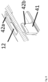
FIGS. 3 to 8 shows the closing mechanism of the slide chamber i.e. how the interconnecting means (41) and the openings (12) mechanically interlock with each other by lateral movement of the base member (40) against the top member (10) by means (42 a) and (42 b). FIG. 3 shows a first step in the interconnection; FIG. 4 shows a next step in the interconnection; FIG. 5 shows a next step in the interconnection; FIG. 6 shows a next step in the interconnection; FIG. 7 shows a variant in the interconnection; and FIG. 8 shows another embodiment of the interconnection.
It should be understood that the drawings are not necessarily to scale, and that like numbers may refer to like features.
DETAILED DESCRIPTION
The slide chamber as disclosed herein is especially useful for optical examination under wet conditions, i.e. under presence of a fluid, for at least one biological tissue located inside in one or more examination chambers (11). The term “optical examination” refers to any examination method known in biology or medicine involving a biological sample and a fluid containing at least one reactant. This term includes visible light microcopy, fluorescence microscopy and staining with or without antibody conjugated dyes. Since the slide chamber according to the invention may comprise one (1) or more, like 2, 4, or even 8 examination chambers and fluids can easily introduced and removed from these, the slide chamber of the invention can be used in a multi-staining and de-staining process, for example as disclosed in U.S. Pat. No. 7,741,045 B2, EP 0810 428 B1, DE10143757, EP3037821A1, EP2725359B1 or WO2017144338A1. It should be noted that the terms “sample”, “biological tissue” or “biological sample” are used synonymous hereinafter.
After the examination is performed, the slide chamber of the invention may be disassembled, so that the sample located on the transparent closure member (30) can be retrieved and optionally stored for further examination. Accordingly, the interconnecting means (41) and the openings (12) are configured to be mechanically disengaged from each other by lateral movement of the of the base member (40) against the top member (10).
Essential for optical examination of a sample covered or at least wetted by a fluid is the water-tight assembly of the parts (members) of the slide chamber. This requires a sufficient pressure on the fluidic seal (20) combining the top member (10) and the transparent closure member (30).
To this end, the interconnecting means (41) of the base member (40) and the openings (12) of the top member (10) are preferably configured as bayonetted joint. As shown in FIGS. 3 to 8 , the interconnecting means (41) of the base member (40) and the openings (12) of the top member (10) are provided with means configured to mechanically interconnect with each other. Such means can be for example one or more notches and a corresponding noses (42 a) and (42 b) or a similar groove-and-spring design.
Preferably, the interconnecting means (41) of the base member (40) and the openings (12) are configured as to create an increasing pressure (force) between the base member (40) and the top member (10) during the closing process, i.e. during lateral movement of the of the base member (40) against the top member (10).
In a first variant, increasing pressure (force) between the base member (40) and the top member (10) is achieved by providing the interconnecting means (41) of the base member (40) and the openings (12) with a tilted shape as shown in FIG. 3 . In another variant, either the interconnecting means (41) of the base member (40) or the openings (12) are provided with a tilted shape as shown in FIG. 7 .
In a further embodiment of the invention, the increasing pressure (force) between the base member (40) top member (10) is provided by the fluidic seal (20), which is slightly compressed during the closing process, i.e. during lateral movement of the of the base member (40) against the top member (10). In this embodiment, it is not necessary to provide the interconnecting means (41) of the base member (40) or the openings (12) with a tilted shape. This embodiment is shown in FIG. 8 .
In a further embodiment of the invention, the top member (10) is provided with a recess for the fluidic seal (20). The recess for the fluidic seal (20) may be provided only around or at the outer circumference of the examination chambers. In a variant thereof, if a plurality of examination chambers is used, the recess and the fluidic seal (20) may be provided around or at the position of each examination chamber. Of course, the shape of the fluidic seal (20) determines the shape of the recess and preferable, the fluidic seal (20) seals off each examination chamber as for example shown in FIG. 1 and the recess has the same shape as the seal.
The fluidic seal (20) and the top member (10) may be provided with one or more mounting means like the projection (22) and the recess/through-hole (13) as shown in FIG. 1 . The fluidic seal (20) may be manufactured from any rubber material known in the art, like silicone rubber.
In best case, a biological tissue is placed within one examination chamber, i.e. the area of the examination chamber and the seal is larger than the sample. However, it might occur that the biological tissue is placed within at least two examination chambers, i.e. either by bad positioning of the sample or if the sample is too large for one examination chamber. In this case, the seal should nonetheless prevent leaking of fluid from one examination chamber to another and/or out of an examination chamber. In other words, the fluidic seal should not be too hard or to soft. Preferred materials for the fluidic seal (20) have a Shore A hardness of 20-50.
For easy positioning of the transparent closure member (30) i.e. of the sample against the examination chambers, the top member (10) is preferable provided with means for holding the transparent closure member (30) as shown by (14) in FIG. 1 . The holder may be a wall or a ridge having at least the same height as the thickness of the transparent closure member (30) and may be provided at all edges of the top member. In a preferred variant, the means for holding the transparent closure member (30) are configured to allow movement of the transparent closure member (30) against the top member (10) before finally assembling the slide chamber. For example, if the transparent closure member (30) is a standard microscopic slide glass, the means for holding the transparent closure member (30) are configured to allow lateral movement of the microscopic slide glass of +−15 mm in longitudinal direction. Again, such movement or adjustment of position is only possible before assembling the slide chamber and not when the interconnecting means (41) and the openings (12) are mechanically interlocked.
To aid assembly and disassembly of the slide chamber, the top member (10) may be provided with at least one grip for example as shown with (14) in FIG. 1 . Further, since many microscopic slide glasses have an writable region (26 in FIG. 1 ) at one end for information purposes, top member (10) may be provided with at least one transparent region at one end (16 in FIG. 1 ) to allow visibility of the writable region of the microscopic slide glass during examination.
Optical examination methods often require adding fluids containing appropriate reactants like dyes to the sample. The slide chamber of the invention is therefore provided with one or more examination chambers (as shown in FIGS. 1 and 2 ), which may be provided by walls attached to or emerging from the upper surface of the top member (10). Usually, the examination chambers have a volume of 0.1 to 5 ml. If more than one examination chamber is provided, they may have the same or a different volume.
In general, “open” examination chambers are preferred. However, in a variant of the invention the examination chambers are provided with a top cover optionally having at least one orifice to allow input and removal of fluids and radiation.
The base member (40) and the top member (10) can be manufactured from PET, PS, PE, PP or COP for example by injection-moulding. Preferable, the top member (10) is transparent to visible and/or UV radiation and has a low fluorescent background, which can be achieved by using COP for manufacturing.
USE OF THE INVENTION
The slide chamber according to the invention may be used in all application of biology or medicine where cells or biological tissue is subjected to optical examination under wet conditions. This includes microscopy, in situ cultivation of cells during microscopy, life cell microscopy or ultrasonic microscopy, preferable involving a process comprising staining, incubation, washing and removal of stain on the biological sample
While various details have been described in conjunction with the exemplary implementations outlined above, various alternatives, modifications, variations, improvements, and/or substantial equivalents, whether known or that are or may be presently unforeseen, may become apparent upon reviewing the foregoing disclosure. Accordingly, the exemplary implementations set forth above, are intended to be illustrative, not limiting.

Claims (17)

What is claimed is:
1. A slide chamber comprising a top member (10), a fluidic seal (20), a transparent closure member (30) and base member (40) wherein the top member (10) is provided with at least one examination chamber (11) and a plurality of openings (12) positioned at two sides of the cover member outside of the examination chamber (11); and
the base member (40) is provided with interconnecting means (41) complementary to the openings (12) of the top member
characterized in that the interconnecting means (41) of the base member (40) and the openings (12) of the top member (10) are configured to mechanically interlock with each other by lateral movement the base member and the transparent closure member move laterally from an unsealed to a sealed, non-leaking position using the interconnecting means, thereby pressing the top member (10) against the transparent closure (30) member in the locked position wherein the interconnecting means (41) is configured as a bayonetted joint.
2. The slide chamber according to claim 1, characterized in that the interconnecting means (41) and the openings (12) are configured to be mechanically disengaged from each other by lateral movement of the base member (40) against the top member (10).
3. The slide chamber according to claim 1, characterized in that the top member (10) is provided with a recess for the fluidic seal (20).
4. The slide chamber according to claim 1, characterized in that the top member (10) is provided with means for holding the transparent closure member (30).
5. The slide chamber according to claim 4, characterized in that means for holding the transparent closure member (30) are configured to allow movement of the transparent closure member (30) against the top member (10).
6. The slide chamber according to claim 4, characterized in that the means for holding the transparent closure member (30) are configured to allow movement of the transparent closure member (30) against the top member (10) before finally assembling the slide chamber.
7. The slide chamber according to claim 1, characterized in that the top member (10) is provided with at least one grip (14).
8. The slide chamber according to claim 1, characterized in that the interconnecting means (41) of the base member (40) and the openings (12) of the top member (10) are configured as bayonetted joint.
9. The slide chamber according to claim 1, characterized in that the fluidic seal (20) has a Shore A hardness of 20-50.
10. The slide chamber according to claim 1, characterized in that the base member (40) and the top member (10) is manufactured from PET, PS, PE, PP or COP.
11. The slide chamber according to claim 1, characterized in that the transparent closure member (30) is a microscopic slide glass.
12. The slide chamber according to claim 1, characterized in that the examination chambers are provided by walls attached to or emerging from the upper surface of the top member (10).
13. The slide chamber according to claim 1, characterized in that the examination chambers are provided with a top cover.
14. A process for preparing at least one biological tissue in the slide chamber according to any of the claims 1 to 13 for optical examination characterized by placing the at least one biological tissue on the transparent closure member (30), combining the top member (10) and the transparent closure member (30) with an interleaved fluidic seal (20);
attaching the base member (40) so that the interconnecting means (41) of the base member (40) are inserted into the openings (12) of the top member (10) and closing the slide chamber by lateral movement of the top member (10) against the transparent closure member (30).
15. The process according to claim 14, characterized in that the at least one biological tissue is placed within at least two examination chambers.
16. The slide chamber of claim 1, wherein the interconnecting means (41) is configured to create an increasing pressure (force) between the base member (40) and the top member (10) during the closing process, i.e. during lateral movement of the of the base member (40) against the top member (10).
17. The slide chamber of claim 16, wherein the increasing pressure is generated by providing at least one of a tilted shape and a compressible fluidic seal (20) on at least one of the base member (40) and the openings (12), during lateral movement of the base member (40) against the top member (10).
US16/794,937 2019-03-19 2020-02-19 Slide chamber Active 2040-03-27 US11633741B2 (en)

Applications Claiming Priority (3)

Application Number Priority Date Filing Date Title
EP19163639 2019-03-19
EP19163639.8 2019-03-19
EP19163639 2019-03-19

Publications (2)

Publication Number Publication Date
US20200298241A1 US20200298241A1 (en) 2020-09-24
US11633741B2 true US11633741B2 (en) 2023-04-25

Family

ID=65818441

Family Applications (1)

Application Number Title Priority Date Filing Date
US16/794,937 Active 2040-03-27 US11633741B2 (en) 2019-03-19 2020-02-19 Slide chamber

Country Status (5)

Country Link
US (1) US11633741B2 (en)
EP (1) EP3711859A1 (en)
JP (1) JP2020153985A (en)
CN (1) CN111721707A (en)
CA (1) CA3076156A1 (en)

Families Citing this family (4)

* Cited by examiner, † Cited by third party
Publication number Priority date Publication date Assignee Title
EP4153775A1 (en) 2020-05-22 2023-03-29 10X Genomics, Inc. Simultaneous spatio-temporal measurement of gene expression and cellular activity
WO2022098810A1 (en) * 2020-11-06 2022-05-12 10X Genomics, Inc. Assay support devices
US20220143620A1 (en) * 2020-11-10 2022-05-12 Fenwal, Inc. Retaining table for fluid processing system
CN116583352A (en) * 2020-12-15 2023-08-11 高露洁-棕榄公司 Microfluidic device for testing aqueous samples containing biological materials

Citations (17)

* Cited by examiner, † Cited by third party
Publication number Priority date Publication date Assignee Title
US3745091A (en) * 1970-11-18 1973-07-10 Miles Lab Biological reaction chamber apparatus
US3883398A (en) 1973-05-07 1975-05-13 Bellco Glass Inc Microculture slide chamber
EP0014007A1 (en) 1979-01-19 1980-08-06 J. Hinrich Dr. Peters Biological container
GB2127577A (en) 1982-09-20 1984-04-11 V Tech Inc Wet-mount microscopic examination slide
EP0210071B1 (en) 1985-07-23 1998-09-30 Hycor Biomedical, Inc. Microscope inspection slide
US20020009390A1 (en) * 1997-02-14 2002-01-24 Murray Lappe System for collecting and locally analyzing a fluid specimen
US20030236497A1 (en) * 2002-06-25 2003-12-25 Radiometer Medical A/S Sampler cap
US20040209349A1 (en) 2003-04-17 2004-10-21 Goldman Ross Bryan Apparatus and method for testing liquid samples
EP1222462B1 (en) 1999-10-14 2004-12-15 Imperial College Innovations Limited Assay device
US20060216211A1 (en) * 2003-10-02 2006-09-28 European Molecular Biology Laboratory Sample holder and microscope assembly
US20070164032A1 (en) * 2006-01-03 2007-07-19 Cronin Edward P Container having a slideable cover
US20100151511A1 (en) * 2008-10-28 2010-06-17 Millipore Corporation Biological culture assembly
US7741045B2 (en) 2006-11-16 2010-06-22 General Electric Company Sequential analysis of biological samples
US20130156644A1 (en) * 2011-12-14 2013-06-20 Samsung Electronics Co., Ltd. Integrated microfluidic cartridge
US20170014824A1 (en) 2015-07-17 2017-01-19 Lawrence M. Boyd Apparatus and method for sorting of cells
DE102015113934A1 (en) 2015-08-21 2017-02-23 Bit Analytical Instruments Gmbh Slide box for an automation system, and container and lid for a slide box
WO2018001767A1 (en) 2016-06-29 2018-01-04 Miltenyi Biotec Gmbh Multilevel disposable cartridge for biological specimens

Family Cites Families (5)

* Cited by examiner, † Cited by third party
Publication number Priority date Publication date Assignee Title
ES2216080T3 (en) 1996-05-29 2004-10-16 Walter Dr. Schubert AUTOMATED DEVICE AND PROCEDURE FOR MEASURING AND DETERMINING MOLECULES OR PARTS OF MOLECULES.
DE10143757A1 (en) 2001-09-06 2003-03-27 Werner M In situ determination of tissue characteristics, useful e.g. for diagnosis of tumors, by using specific detection agents that are transiently labeled
EP2725358A1 (en) 2012-10-23 2014-04-30 Miltenyi Biotec GmbH Release system for cell-antibody-substrate conjugates containing a polyethylene glycol spacer unit
EP3037820A1 (en) 2014-12-27 2016-06-29 Miltenyi Biotec GmbH Cell detection methods and reagents having a releasable labelling moiety
US20170241911A1 (en) 2016-02-22 2017-08-24 Miltenyi Biotec Gmbh Automated analysis tool for biological specimens

Patent Citations (17)

* Cited by examiner, † Cited by third party
Publication number Priority date Publication date Assignee Title
US3745091A (en) * 1970-11-18 1973-07-10 Miles Lab Biological reaction chamber apparatus
US3883398A (en) 1973-05-07 1975-05-13 Bellco Glass Inc Microculture slide chamber
EP0014007A1 (en) 1979-01-19 1980-08-06 J. Hinrich Dr. Peters Biological container
GB2127577A (en) 1982-09-20 1984-04-11 V Tech Inc Wet-mount microscopic examination slide
EP0210071B1 (en) 1985-07-23 1998-09-30 Hycor Biomedical, Inc. Microscope inspection slide
US20020009390A1 (en) * 1997-02-14 2002-01-24 Murray Lappe System for collecting and locally analyzing a fluid specimen
EP1222462B1 (en) 1999-10-14 2004-12-15 Imperial College Innovations Limited Assay device
US20030236497A1 (en) * 2002-06-25 2003-12-25 Radiometer Medical A/S Sampler cap
US20040209349A1 (en) 2003-04-17 2004-10-21 Goldman Ross Bryan Apparatus and method for testing liquid samples
US20060216211A1 (en) * 2003-10-02 2006-09-28 European Molecular Biology Laboratory Sample holder and microscope assembly
US20070164032A1 (en) * 2006-01-03 2007-07-19 Cronin Edward P Container having a slideable cover
US7741045B2 (en) 2006-11-16 2010-06-22 General Electric Company Sequential analysis of biological samples
US20100151511A1 (en) * 2008-10-28 2010-06-17 Millipore Corporation Biological culture assembly
US20130156644A1 (en) * 2011-12-14 2013-06-20 Samsung Electronics Co., Ltd. Integrated microfluidic cartridge
US20170014824A1 (en) 2015-07-17 2017-01-19 Lawrence M. Boyd Apparatus and method for sorting of cells
DE102015113934A1 (en) 2015-08-21 2017-02-23 Bit Analytical Instruments Gmbh Slide box for an automation system, and container and lid for a slide box
WO2018001767A1 (en) 2016-06-29 2018-01-04 Miltenyi Biotec Gmbh Multilevel disposable cartridge for biological specimens

Also Published As

Publication number Publication date
CA3076156A1 (en) 2020-09-19
EP3711859A1 (en) 2020-09-23
CN111721707A (en) 2020-09-29
US20200298241A1 (en) 2020-09-24
JP2020153985A (en) 2020-09-24

Similar Documents

Publication Publication Date Title
US11633741B2 (en) Slide chamber
CA2684095C (en) Devices and methods for detecting analytes
US7604777B2 (en) Cartridge for containing a specimen sample for optical analysis
US9150907B2 (en) Microfluidic flow cell assemblies and method of use
US20100326587A1 (en) Upon a cartridge for containing a specimen sample for optical analysis
US20120190105A1 (en) Cartridge for MEMS particle sorting system
JP4731847B2 (en) Petri dish, chamber apparatus, optical microscope observation method and sample analysis method
JP6723541B2 (en) Imaging microfluidic flow cell assembly and method of use thereof
EP3143380B1 (en) Microfluidic flow cell assemblies and method of use
WO2019116209A1 (en) Microfluidic chip and microscopic image system
CN103842086A (en) Sample liquid injection jig set
CN109475864B (en) Multi-stage disposable cartridge for biological samples
US9080941B2 (en) Microfluidic flow cell assemblies for imaging and method of use
WO2010077784A1 (en) Test cartridges for flow assays and methods for their use
US20150177231A9 (en) Assays
US20220065757A1 (en) Microfluidic Device for Image Multiplexing
WO2023088563A1 (en) Flow cell
EP4171813A1 (en) Microfluidic chip and pumping device

Legal Events

Date Code Title Description
FEPP Fee payment procedure

Free format text: ENTITY STATUS SET TO UNDISCOUNTED (ORIGINAL EVENT CODE: BIG.); ENTITY STATUS OF PATENT OWNER: LARGE ENTITY

STPP Information on status: patent application and granting procedure in general

Free format text: DOCKETED NEW CASE - READY FOR EXAMINATION

STPP Information on status: patent application and granting procedure in general

Free format text: NON FINAL ACTION MAILED

STPP Information on status: patent application and granting procedure in general

Free format text: RESPONSE TO NON-FINAL OFFICE ACTION ENTERED AND FORWARDED TO EXAMINER

STPP Information on status: patent application and granting procedure in general

Free format text: FINAL REJECTION MAILED

STCB Information on status: application discontinuation

Free format text: ABANDONED -- FAILURE TO RESPOND TO AN OFFICE ACTION

STPP Information on status: patent application and granting procedure in general

Free format text: DOCKETED NEW CASE - READY FOR EXAMINATION

STCF Information on status: patent grant

Free format text: PATENTED CASE