EP0210071A2 - Microscope inspection slide - Google Patents
Microscope inspection slide Download PDFInfo
- Publication number
- EP0210071A2 EP0210071A2 EP86305615A EP86305615A EP0210071A2 EP 0210071 A2 EP0210071 A2 EP 0210071A2 EP 86305615 A EP86305615 A EP 86305615A EP 86305615 A EP86305615 A EP 86305615A EP 0210071 A2 EP0210071 A2 EP 0210071A2
- Authority
- EP
- European Patent Office
- Prior art keywords
- examination chamber
- examination
- base plate
- cover plate
- chamber roof
- Prior art date
- Legal status (The legal status is an assumption and is not a legal conclusion. Google has not performed a legal analysis and makes no representation as to the accuracy of the status listed.)
- Granted
Links
Images


Classifications
-
- G—PHYSICS
- G02—OPTICS
- G02B—OPTICAL ELEMENTS, SYSTEMS OR APPARATUS
- G02B21/00—Microscopes
- G02B21/34—Microscope slides, e.g. mounting specimens on microscope slides
Definitions
- Laboratory analysis of biological fluids such as blood, spinal fluid, cell cultures and urine can include microscopic examination of a specimen liquid to determine the presence or concentration of suspended particulate matter such as cells.
- microscopic examination of liquid specimens has been accomplished by placing a drop of the specimen liquid on a flat transparent microscope slide and then placing a thin flat transparent coverslip over the specimen. The weight of the coverslip and the inherent capillation between the liquid specimen the microscope slide and the coverslip presses the coverslip against the slide and distributes the liquid as a film in the space between the slide and the coverslip. The slide is then placed on a microscope stage and the liquid specimen between the slide and the coverslip is examined.
- the thickness of each specimen must be essentially equal or again must be known so that calculations of volumes in which the particulate species are suspended can be made. Assumptions regarding the thickness of liquid specimens are not useful because uncontrollable variables such as variations in the surface tension from sample to sample which substantially effects thickness, variations in the amount of liquid used for.preparing slide specimens, entrapment of air between the slide and coverslip and variations in the pressure exerted between the coverslip and the slide all cause differences in specimen thickness.
- degrading the utility of such micrcscopic counts are perturbations in the distribution of particulates in specimens caused by inadvertent translational movement of coverslips with respect to slides during preparation of slide/coverslip assemblies which can result in non-uniformity cf the distribution of particulates in specimens.
- the depth of examination chambers should be maintained within the depth of field of instruments used to examine specimens.
- the depth of the examination chamber with respect to the microscope should be maintained at 0.004 inches which is equal to or less than one focal plane of optical instruments used for this type of laboratory work.
- the present invention which provides inspection slides, with fixed coverslips, having examination chambers with constant depths that can be maintained shorter than the depth of field for inspecting optical instruments and also has examination chambers from which entraped gases can be readily bleed, and from which excess specimen fluids can be readily drained.
- the examination chamber roofs which are recessed, have smaller surface areas than the examination chamber floor surfaces, and surrounding the examination chamber roofs are depth control ridges spaced a uniform distance from the examination chamber roof surfaces. Additionally the depth control ridges extend beyond the outer edge of the examination chamber floor surfaces when a cover plate and base plate are assembled. Therefore the examination chamber roofs are displaced from the examination chamber floors by distances determined by the depth control ridges.
- each depth control ridge In combination with the examination chamber floor and roof surfaces, and the depth control ridges are at least one notch cut into each depth control ridge which extends from outside the areas defined by the examination chamber floor surfaces and then over each examination chamber floor surface to the examination roof surface. These notches provide channels for bleeding entraped gases from the examination chambers and for draining excess specimen fluids from the examination chambers.
- Each of the examination chambers on an inspection slide of the present invention has an opening facing an edge of the base plate. These openings are formed by a ramp surface intersecting each examination chamber floor surface and by the examination chamber roof positioned above the intersection of the examination chamber floor and the ramp surface.
- This configuration of ramp surface and examination chamber roof permits efficient charging of the examination chamber with specimen fluid. Such charging can be accomplished by a pipette or dropper positioned at the opening to introduce a drop of specimen fluid, the specimen fluid will wet both the examination chamber roof and floor.
- the wetted examination chamber roof and floor guides the specimen in to fill the examination chamber by capillation. During the filling of an examination chamber entraped gases are bleed
- An inspection slide according to the present invention is assembled by placing a cover plate fabricated from transparent plastic and having at least one coverslip portion on top of a base plate also fabricated from transparent plastic and having at least one examination chamber floor which is a flat and optically smooth surface.
- the coverslip portion of the cover plate is positioned so that it essentially overlays the examination chamber floor. This configuration is then maintained by bonding the cover plate to the base plate.
- the bonds between the base plate and the cover plate are made at locations remote from the examination chamber so that dimensional distortions inevitably associated with bonding plastic structures are minimized by the distances between the bonding points and the examination chambers.
- Examination chambers in the inspection slide of the present invention are formed from the abutting contact of the coverslip portior. of a cover plate onto the examination chamber floor surface defined on a base plate.
- the abutting contact is maintained by bonding portions of the cover plate to the base plate.
- a second function provided by the bonded portions of the cover plate and base plate besides maintaining contact between these two plates is the isolation of examination chambers so that a liquid specimen which drains from one examination chamber will not migrate to a second examination chamber and contaminate a second specimen.
- the examination chamber floor surfaces on a base plate are flat optically smooth surfaces which are raised above a main base plate surface, and the coverslip portions of a cover plate include examination chamber roofs which are also flat and optically smooth surfaces but are recessed into the cover plate and are of a similar general shape as the examination chamber floor surfaces.
- the examination chamber roofs through the notches in the depth control ridge and after filling of an examination chamber excess specimen fluid is drained through the same notch. Capillation in addition to providing a mechanism for filling examination chambers with specimen fluids also maintains a constant depth between the examination chamber roofs and floors by attracting the roofs toward the floors to distances determined by the depth control ridges through the medium of the specimen fluids.
- the examination chamber roof can be configured to overhang the ramp surface of the present invention in one embodiment and to include a lip which extends from the examination chamber roof to the ramp surface where it is bonded to the ramp so as to reduce the area cf the opening and thus decrease evaporation rates for specimen fluids. This lip extends along approximately seventy percent of the length of the examination chamber roof edge adjacent the opening used to charge the examination chamber but does not extend to the ends of the opening.
- a drop of specimen fluid can be placed for charging the examination chamber. Because the lip from the examination chamber roof will provide a guiding surface the specimen fluid will first be drawn along the length of the lip and then will be drawn into the examination chamber. In accordance with the present invention the lip is positioned over the ramp surface so that a volume of specimen fluid is positioned in front of the examination chamber. This volume of fluid must be evaporated before that in the examination chamber can be evaporated.
- Inspection slide 10 includes cover plate 12 and base plate 14.
- a top plan view of an assembled inspection slide 10 as shown in FIG. 1 is shown in FIG. 2.
- the base plate 14 for an inspection slide 10 includes examination chamber floor surfaces 16 which are flat optically smooth surfaces.
- one or more examination chamber floor surfaces 16 can be oriented on a base plate 14.
- the examination chamber floor surfaces 16 are oriented on the base plate 14 so that the examination chamber floor surface 16 is parallel to the bottom surface 18 of the base plate 14. Having the examination chamber floor surface 16 parallel to the bottom surface 18 of the base plate 14 assures that when the base plate 14 is positioned on the stage of an optical instrument having its optical axes perpendicular to the stage the examination chamber floor surface 16 will also be perpendicular to the optical axis of the instrument.
- the examination chamber floor surfaces 16 are also raised above an upper deck 20 of the base plate 14.
- Cover plate 12 has recessed below a lower surface 22 examination chamber roofs 24, which like the examination chamber floor surfaces 16 are flat and optically smooth surfaces.
- the examination chamber roofs 24 have surface areas which are generally the same shape as those of the examination chamber floors surfaces 16 but the examination chamber roofs 24 have shorter linear dimensions, L and W (See FIG 1).
- Surrounding the examination chamber roofs 24 are depth ccntrol ridges 26 which are also recessed below the lower surface 22 of the cover plate 12.
- the depth control ridges 26 are not recessed as deep as the examination chamber roofs 24, but the depth control ridges 26 do extend from the examination charter roofs 24 out to locations beyond the surface areas of the examination chamber floor surfaces 16. Therefore, the cover plates 12 can be positioned on the base plates 14 so that the examination chamber roofs 24 are supported via the depth control ridges 26 at constant distances determined by the depth control ridges 26 from the examination chamber floor surfaces 16.
- the depth control ridges 26 extend from the examination chamber roof 24 on all sides except one. That side being where the examination chamber 28 is charged with specimen fluid.
- the depth control ridges 26 are preferably maintained so as to have the examination chamber roofs 24 recessed 0.0045 inches + 0.0005 inches from the bottom of the depth control ridges 26.
- the present invention can also be used for special applications such as hemacytometry which previously required accurately ground and polished glass slide/coverslip combinations.
- a counting grid is etched on the chamber roofs 24 using known techniques, and the depth control ridges 26 are preferably maintained so as to have the examination chamber roofs 24 recessed 0.010 inches + 0.001 inches from the bottom of the depth control ridges 26.
- the energy directing ridges 30 are located between examination chamber floor surfaces 16.
- Such positioning of the cover plate 12 with respect to the base plate 14 is assured by tabs 32 located between the examination chamber floor surfaces 16, at the edges of the base plate 14 and raised above the examination chamber floor surfaces 16 a distance essentially equal to the thickness, of the cover plate 12.
- the tabs 32 between the examination chamber floor surfaces 16 assure proper positioning of the cover plate 12 in the dimension between the tabs 32 with respect to the base plate 14 while the energy directing ridges 30 which extend from the lower surface 22 of the cover plat ⁇ 12 and which are essentially dimensioned to fit between and in close proximity to the supports 34 for the examination chamber floor surfaces 16 assure proper positioning of the cover plate 12 in the dimension perpendicular to that defined by tabs 32.
- the energy directing ridges 30 are ultrasonically welded to the base plate 14 using techniques known in the art.
- each examination chamber 28 there is a ramp surface 38 extending up from an outer edge of the base plate 14 to the examination chamber floor surface 16 and intersecting the examination chamber floor surface 16 along a line just under the examination chamber roof 24.
- the opening between the examination chamber floor surface 16 and the examination chamber roof 24 defined along the line where the ramp 38 and examination chamber floor surface 16 intersect provides a gate for charging the examination chamber 28 with a specimen fluid. Capillation draws a fluid which is positioned on the ramp 38 at the edge of examination chamber roof 24 into the examination chamber 28.
- the cover plate 12 is recessed back so that the edge of the examination chamber roof 24 is positioned essentially directly above the intersection of the examination chamber floor surface 16 and ramp surface 38 (see FIGS. 4 and 5 ).
- These recesses provide charging ports 40 where a drop of specimen fluid can be positioned and taken by capillation into the examination chambers 28.
- Another feature of this embodiment is the extension of the examination roof 24 beyond the intersection of the examination chamber floor surface 16 and the ramp 38 along the section between charging ports 40, and the provision of a lip ridge 42 along the length of the examination chamber roof 24 which approaches the surface of the ramp 38 where it is ultrasonically welded when cover plate 12 is welded to base plate 14. A volume having a triangular cross sectional area is then defined between lip ridge 42, examination chamber roof 24 and ramp 38. Placing a drop of specimen fluid at a charging port 40 will result in the fluid being drawn by capillation along the length of the lip ridge 42 because the depth from the examination chamber roof 24 to the ramp 38 is greater than the distance between the examination chamber roof 24 to the exmination chamber floor surface 16.
- the specimen fluid After filling the volume along the length of the lip ridge 42 the specimen fluid will evenly fill the examination chamber from the opening back.
- a reservoir is effectively formed behind the lip ridge 42. Evaporation of the specimen fluid in the examination chamber 28 can not begin until the fluid in the reservoir is first evaporated.
- the reservoir additionally provides for contained storage of specimen fluid to prevent contamination of optics by careless use of the inspecting instrument.
- notches 44 which are cut out to the outer edges of the depth control ridges 26 so that both entraped gases and excess fluid can be drained from the examination chambers 28 to ensure complete filling of the examination chamber with specimen fluid.
- the notches 44 extend from between the examination chamber roof 24 and floor 16 out beyond the edge of the examination chamber floor surface 16 so both gases and fluids can easily be drained from the examination chamber 28.
- the volumes of the openings provided by the notches 44 are sized so as not to provide preferential capillation for draining specimen fluid from the examination chamber.
- Inspection plates 10 of the present invention may be fabricated from acrylic plastic by injection molding the cover plate 12 and base plate 14 and then ultrasonically welding them together.
- the acrylic plastic should have an index of refraction essentially equal to glass and should be of a grade which is wettable and free from acid affinity.
- the examination chamber roof 24 and floor 16 surfaces can be formed by use of mold surfaces which are polished optically flat.
Abstract
Description
- Laboratory analysis of biological fluids such as blood, spinal fluid, cell cultures and urine can include microscopic examination of a specimen liquid to determine the presence or concentration of suspended particulate matter such as cells. Typically, microscopic examination of liquid specimens has been accomplished by placing a drop of the specimen liquid on a flat transparent microscope slide and then placing a thin flat transparent coverslip over the specimen. The weight of the coverslip and the inherent capillation between the liquid specimen the microscope slide and the coverslip presses the coverslip against the slide and distributes the liquid as a film in the space between the slide and the coverslip. The slide is then placed on a microscope stage and the liquid specimen between the slide and the coverslip is examined.
- The procedures involved in preparing a slide, liquid specimen and coverslip combinations for optical examination requires an excessive amount of manual manipulation which inevitably results in uncontrollable and unpredictable variations in the specimen examined. An inevitable and most critical variation resulting from use of the above described slide/coverslip combination is the thickness of the specimen between the slide and the coverslip. This variation is important because when a microscopic examination of the specimen is made such examination is over an area of the specimen and provides a count of selected particulate species. Determination of the useful parameter - concentration of particulate species - requires the multiplication of the examined area by the depth of the specimen to obtain the volume of specimen in which the counted particulate matter is suspended. To determine relative concentration differences between counted particulate species in multiple specimens or to determine concentration differences between a selected specimen and a standard specimen the thickness of each specimen must be essentially equal or again must be known so that calculations of volumes in which the particulate species are suspended can be made. Assumptions regarding the thickness of liquid specimens are not useful because uncontrollable variables such as variations in the surface tension from sample to sample which substantially effects thickness, variations in the amount of liquid used for.preparing slide specimens, entrapment of air between the slide and coverslip and variations in the pressure exerted between the coverslip and the slide all cause differences in specimen thickness. Further, degrading the utility of such micrcscopic counts are perturbations in the distribution of particulates in specimens caused by inadvertent translational movement of coverslips with respect to slides during preparation of slide/coverslip assemblies which can result in non-uniformity cf the distribution of particulates in specimens.
- Attempts have been made to provide inspection slides which avoid the above described limitations of separate slide/coverslip combinations. Some of these efforts have been based on molding unitary transparent plastic slide/coverslip structures with a liquid specimen drawn into examination chambers by capillation. Such devices are disclosed in United States patents: 3,961,346; 3,777,283; and 4,2°9,441. Other efforts include fabrication of examanation chambers from two plastic molded components bonded or attached together as slide/coverslip structures into which again liquid specimens are drawn by capillation. Such devices are disclosed in United States patent 3,565,537 and United Kingdom application 2,127,557A. All of these attempts to provide useful inspection slide designs have failed due to such deficiencies as: inability to bleed off entraped gases in the examination chambers; inability to provide parallel floor and roof surfaces for the examination chambers which are accurately distanced from each other; inability to provide sample chambers which have thicknesses less than the depth of field of optical instruments used to examine specimens which can cause eye fatigue to the technician who is required to refocus the instrument in order to complete an examination of a specimen, inability to provide accurate bonding systems for maintaining contact between slide/coverslip structures such as that disclosed in United States patent 3,565,537 which provides no expansion space for melted bonding ridges; or excessively large openings from the examination chambers which enhance evaporation of specimen fluids and accordingly decrease the time between charging an examination chamber and the time when the specimen must be examined.
- Accurately spacing and maintaining the floor and roof surfaces of an examination chamber from each other is a critical requirement for assuring that known volumes of specimen liquid are introduced into examination chambers so that accurate determinations of the concentration of particulate matter in specimens by counting the suspended particulate matter can be made. In addition to errors caused by variable specimen volumes, errors in counting can also very readily arise if the optical instrument, such as a microscope, used to view the suspended particulate matter is not in focus throughout the entire depth of the specimen in the examination chamber. These errors arise because as the optical instrument is refocused to count particulate matter at a new depth that particulate matter previously counted can migrate to the new depth where the instrument is focused or particulate matter not previously counted can migrate away from the depth where the instrument is focused. Even if a skilled technician makes the examination, errors due to refocussing are inevitable because the refocussing inevitably causes extreme eye fatigue. Therefore, the depth of examination chambers should be maintained within the depth of field of instruments used to examine specimens. For microscopes used to count particulate species in most biological fluids the depth of the examination chamber with respect to the microscope should be maintained at 0.004 inches which is equal to or less than one focal plane of optical instruments used for this type of laboratory work. Concurrent with the requirement to maintain the specimen in the depth of field of the inspecting optical instrument is the associated requirement of assuring that the optical axis of the inspecting instrument be perpendicular to the floor surface of the examination chamber so that as the inspection slide is translated to permit examination of different volumes of the specimen the specimen remains in the depth of field of the instrument.
- These requirements are met by the present invention which provides inspection slides, with fixed coverslips, having examination chambers with constant depths that can be maintained shorter than the depth of field for inspecting optical instruments and also has examination chambers from which entraped gases can be readily bleed, and from which excess specimen fluids can be readily drained.
- which are recessed, have smaller surface areas than the examination chamber floor surfaces, and surrounding the examination chamber roofs are depth control ridges spaced a uniform distance from the examination chamber roof surfaces. Additionally the depth control ridges extend beyond the outer edge of the examination chamber floor surfaces when a cover plate and base plate are assembled. Therefore the examination chamber roofs are displaced from the examination chamber floors by distances determined by the depth control ridges.
- In combination with the examination chamber floor and roof surfaces, and the depth control ridges are at least one notch cut into each depth control ridge which extends from outside the areas defined by the examination chamber floor surfaces and then over each examination chamber floor surface to the examination roof surface. These notches provide channels for bleeding entraped gases from the examination chambers and for draining excess specimen fluids from the examination chambers.
- Each of the examination chambers on an inspection slide of the present invention has an opening facing an edge of the base plate. These openings are formed by a ramp surface intersecting each examination chamber floor surface and by the examination chamber roof positioned above the intersection of the examination chamber floor and the ramp surface. This configuration of ramp surface and examination chamber roof permits efficient charging of the examination chamber with specimen fluid. Such charging can be accomplished by a pipette or dropper positioned at the opening to introduce a drop of specimen fluid, the specimen fluid will wet both the examination chamber roof and floor. The wetted examination chamber roof and floor guides the specimen in to fill the examination chamber by capillation. During the filling of an examination chamber entraped gases are bleed
- An inspection slide according to the present invention is assembled by placing a cover plate fabricated from transparent plastic and having at least one coverslip portion on top of a base plate also fabricated from transparent plastic and having at least one examination chamber floor which is a flat and optically smooth surface. The coverslip portion of the cover plate is positioned so that it essentially overlays the examination chamber floor. This configuration is then maintained by bonding the cover plate to the base plate. The bonds between the base plate and the cover plate are made at locations remote from the examination chamber so that dimensional distortions inevitably associated with bonding plastic structures are minimized by the distances between the bonding points and the examination chambers.
- Examination chambers in the inspection slide of the present invention are formed from the abutting contact of the coverslip portior. of a cover plate onto the examination chamber floor surface defined on a base plate. The abutting contact is maintained by bonding portions of the cover plate to the base plate. A second function provided by the bonded portions of the cover plate and base plate besides maintaining contact between these two plates is the isolation of examination chambers so that a liquid specimen which drains from one examination chamber will not migrate to a second examination chamber and contaminate a second specimen. The examination chamber floor surfaces on a base plate are flat optically smooth surfaces which are raised above a main base plate surface, and the coverslip portions of a cover plate include examination chamber roofs which are also flat and optically smooth surfaces but are recessed into the cover plate and are of a similar general shape as the examination chamber floor surfaces. However the examination chamber roofs, through the notches in the depth control ridge and after filling of an examination chamber excess specimen fluid is drained through the same notch. Capillation in addition to providing a mechanism for filling examination chambers with specimen fluids also maintains a constant depth between the examination chamber roofs and floors by attracting the roofs toward the floors to distances determined by the depth control ridges through the medium of the specimen fluids.
- Though capillation retains specimen fluids in examination chambers, evaporation of the specimen fluids through the opening to the examination chambers can render a charged examination chamber useless if sufficient time lapses between the filling of the examination chamber and the examination of the chamber under an optical instrument. To preclude such a problem the examination chamber roof can be configured to overhang the ramp surface of the present invention in one embodiment and to include a lip which extends from the examination chamber roof to the ramp surface where it is bonded to the ramp so as to reduce the area cf the opening and thus decrease evaporation rates for specimen fluids. This lip extends along approximately seventy percent of the length of the examination chamber roof edge adjacent the opening used to charge the examination chamber but does not extend to the ends of the opening. At the ends of the opening a drop of specimen fluid can be placed for charging the examination chamber. Because the lip from the examination chamber roof will provide a guiding surface the specimen fluid will first be drawn along the length of the lip and then will be drawn into the examination chamber. In accordance with the present invention the lip is positioned over the ramp surface so that a volume of specimen fluid is positioned in front of the examination chamber. This volume of fluid must be evaporated before that in the examination chamber can be evaporated.
- In the drawings:
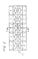
- FIG. 1 is an exploded perspective view of an inspection slide according to the present invention;
- FIG. 2 is a top plan view of an assembled inspection slide according to the present invention;
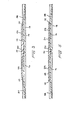
- FIG. 3 is an enlarged sectional view of an inspection slide according to the present invention showing an examination chamber that is taken along line 3-3 of FIG. 2;
- FIG. 4 is a top plan view of an assembled inspection slide with decreased openings to examination chambers; and,
- FIG. 5 is an enlarged sectional view of an inspection slide according to the embodiment shown in FIG. 4 showing an examination chamber that is taken along line 5-5 of FIG. 4.
- Corresponding components are designated by the same reference numerals throughout the various figures.
- Referring now to the drawings, an inspection slide according to the present invention is illustrated in FIG. 1 where it is generally designated by
reference numeral 10.Inspection slide 10 includes cover plate 12 andbase plate 14. A top plan view of an assembledinspection slide 10 as shown in FIG. 1 is shown in FIG. 2. - The
base plate 14 for aninspection slide 10 includes examination chamber floor surfaces 16 which are flat optically smooth surfaces. In accordance with the present invention one or more examination chamber floor surfaces 16 can be oriented on abase plate 14. The examination chamber floor surfaces 16 are oriented on thebase plate 14 so that the examinationchamber floor surface 16 is parallel to thebottom surface 18 of thebase plate 14. Having the examinationchamber floor surface 16 parallel to thebottom surface 18 of thebase plate 14 assures that when thebase plate 14 is positioned on the stage of an optical instrument having its optical axes perpendicular to the stage the examinationchamber floor surface 16 will also be perpendicular to the optical axis of the instrument. In addition to being parallel to thebottom surface 18 of thebase plate 14 the examination chamber floor surfaces 16 are also raised above anupper deck 20 of thebase plate 14. - Cover plate 12 has recessed below a
lower surface 22examination chamber roofs 24, which like the examination chamber floor surfaces 16 are flat and optically smooth surfaces. Theexamination chamber roofs 24 have surface areas which are generally the same shape as those of the examination chamber floors surfaces 16 but theexamination chamber roofs 24 have shorter linear dimensions, L and W (See FIG 1). Surrounding theexamination chamber roofs 24 aredepth ccntrol ridges 26 which are also recessed below thelower surface 22 of the cover plate 12. Thedepth control ridges 26 are not recessed as deep as theexamination chamber roofs 24, but thedepth control ridges 26 do extend from theexamination charter roofs 24 out to locations beyond the surface areas of the examination chamber floor surfaces 16. Therefore, the cover plates 12 can be positioned on thebase plates 14 so that theexamination chamber roofs 24 are supported via thedepth control ridges 26 at constant distances determined by thedepth control ridges 26 from the examination chamber floor surfaces 16. - 7he
depth control ridges 26 extend from theexamination chamber roof 24 on all sides except one. That side being where theexamination chamber 28 is charged with specimen fluid. In order for theexamination chamber 28 to have a depth which is less than the depth of field for optical instruments which would normally be used to examine specimens inexamination chambers 28 thedepth control ridges 26 are preferably maintained so as to have theexamination chamber roofs 24 recessed 0.0045 inches + 0.0005 inches from the bottom of thedepth control ridges 26. The present invention can also be used for special applications such as hemacytometry which previously required accurately ground and polished glass slide/coverslip combinations. For this application a counting grid is etched on thechamber roofs 24 using known techniques, and thedepth control ridges 26 are preferably maintained so as to have theexamination chamber roofs 24 recessed 0.010 inches + 0.001 inches from the bottom of thedepth control ridges 26. - Extending from the
lower surface 22 of the cover plate 12 areenergy directing ridges 30. When the cover plate 12 is positioned on top of thebase plate 14, theenergy directing ridges 30 are located between examination chamber floor surfaces 16. Such positioning of the cover plate 12 with respect to thebase plate 14 is assured bytabs 32 located between the examination chamber floor surfaces 16, at the edges of thebase plate 14 and raised above the examination chamber floor surfaces 16 a distance essentially equal to the thickness, of the cover plate 12. Thetabs 32 between the examination chamber floor surfaces 16 assure proper positioning of the cover plate 12 in the dimension between thetabs 32 with respect to thebase plate 14 while theenergy directing ridges 30 which extend from thelower surface 22 of the cover platε 12 and which are essentially dimensioned to fit between and in close proximity to the supports 34 for the examination chamber floor surfaces 16 assure proper positioning of the cover plate 12 in the dimension perpendicular to that defined bytabs 32. When the cover plate 12 is properly positioned onbase plate 14 theenergy directing ridges 30 are ultrasonically welded to thebase plate 14 using techniques known in the art. - For each
examination chamber 28 there is aramp surface 38 extending up from an outer edge of thebase plate 14 to the examinationchamber floor surface 16 and intersecting the examinationchamber floor surface 16 along a line just under theexamination chamber roof 24. The opening between the examinationchamber floor surface 16 and theexamination chamber roof 24 defined along the line where theramp 38 and examinationchamber floor surface 16 intersect provides a gate for charging theexamination chamber 28 with a specimen fluid. Capillation draws a fluid which is positioned on theramp 38 at the edge ofexamination chamber roof 24 into theexamination chamber 28. - Three disadvantages associated with charging examination chambers by capillation are:
- (i) the specimen fluid can evaporate through the same opening used to charge the examination chamber;
- (ii) the examination chamber may not be evenly and quickly filled with specimen fluid; and,
- (iii) a careless user can contaminate the optics of an optical instrument with excess specimen fluid retained at the edge of the opening to the examination chamber.
- The
examination chamber roof 24, in another embodiment of the present invention which addresses these disadvantages, extends over the intersection 01 the examination cnamDer floor lb and theramp 38 along most of the entire length of that intersection. However, at the two ends of that intersection for eachexamination chamber 28 the cover plate 12 is recessed back so that the edge of theexamination chamber roof 24 is positioned essentially directly above the intersection of the examinationchamber floor surface 16 and ramp surface 38 (see FIGS. 4 and 5). These recesses provide chargingports 40 where a drop of specimen fluid can be positioned and taken by capillation into theexamination chambers 28. Another feature of this embodiment is the extension of theexamination roof 24 beyond the intersection of the examinationchamber floor surface 16 and theramp 38 along the section between chargingports 40, and the provision of alip ridge 42 along the length of theexamination chamber roof 24 which approaches the surface of theramp 38 where it is ultrasonically welded when cover plate 12 is welded tobase plate 14. A volume having a triangular cross sectional area is then defined betweenlip ridge 42,examination chamber roof 24 andramp 38. Placing a drop of specimen fluid at a chargingport 40 will result in the fluid being drawn by capillation along the length of thelip ridge 42 because the depth from theexamination chamber roof 24 to theramp 38 is greater than the distance between theexamination chamber roof 24 to the exminationchamber floor surface 16. After filling the volume along the length of thelip ridge 42 the specimen fluid will evenly fill the examination chamber from the opening back. When theexamination chamber 28 is filled, a reservoir is effectively formed behind thelip ridge 42. Evaporation of the specimen fluid in theexamination chamber 28 can not begin until the fluid in the reservoir is first evaporated. The reservoir additionally provides for contained storage of specimen fluid to prevent contamination of optics by careless use of the inspecting instrument. - Whether the embodiment for the opening to the
examination chambers 28 shown in FIGS. 2 and 3 or that shown in FIGS. 4 and 5 is used there are positioned at the back portion of eachexamination chamber 28 on thedepth control ridges 26 notches 44 which are cut out to the outer edges of thedepth control ridges 26 so that both entraped gases and excess fluid can be drained from theexamination chambers 28 to ensure complete filling of the examination chamber with specimen fluid. Thenotches 44 extend from between theexamination chamber roof 24 andfloor 16 out beyond the edge of the examinationchamber floor surface 16 so both gases and fluids can easily be drained from theexamination chamber 28. The volumes of the openings provided by thenotches 44 are sized so as not to provide preferential capillation for draining specimen fluid from the examination chamber. - When excess specimen fluid is drained from an
examination chamber 26 that fluid does not contaminate the specimen fluids in any adjoiningexamination chamber 28 because theenergy directing ridges 30 which are ultrasonically welded to the base plate 12 completely enclose each examination chamber and, therefore, prevent migration of specimen fluid from oneexamination chamber 28 to another. -
Inspection plates 10 of the present invention may be fabricated from acrylic plastic by injection molding the cover plate 12 andbase plate 14 and then ultrasonically welding them together. The acrylic plastic should have an index of refraction essentially equal to glass and should be of a grade which is wettable and free from acid affinity. Theexamination chamber roof 24 andfloor 16 surfaces can be formed by use of mold surfaces which are polished optically flat. - To facilitate counting suspended particulate materials appropriate grid lines can be etched onto the surfaces of the cover plates 12 by techniques which are known in the art.
Claims (6)
Applications Claiming Priority (2)
| Application Number | Priority Date | Filing Date | Title |
|---|---|---|---|
| US758056 | 1985-07-23 | ||
| US06/758,056 US4637693A (en) | 1985-07-23 | 1985-07-23 | Microscope inspection slide |
Publications (3)
| Publication Number | Publication Date |
|---|---|
| EP0210071A2 true EP0210071A2 (en) | 1987-01-28 |
| EP0210071A3 EP0210071A3 (en) | 1988-09-07 |
| EP0210071B1 EP0210071B1 (en) | 1998-09-30 |
Family
ID=25050314
Family Applications (1)
| Application Number | Title | Priority Date | Filing Date |
|---|---|---|---|
| EP86305615A Expired - Lifetime EP0210071B1 (en) | 1985-07-23 | 1986-07-22 | Microscope inspection slide |
Country Status (4)
| Country | Link |
|---|---|
| US (1) | US4637693A (en) |
| EP (1) | EP0210071B1 (en) |
| JP (1) | JPH0697307B2 (en) |
| DE (1) | DE3650701T2 (en) |
Cited By (7)
| Publication number | Priority date | Publication date | Assignee | Title |
|---|---|---|---|---|
| EP0326349A2 (en) * | 1988-01-27 | 1989-08-02 | Hycor Biomedical | Patterned plastic optical components |
| DE9203917U1 (en) * | 1992-03-24 | 1992-05-14 | Garnjost, Achim, Dr.Med., 5880 Luedenscheid, De | |
| DE9203921U1 (en) * | 1992-03-24 | 1992-08-06 | Garnjost, Achim, Dr.Med., 5880 Luedenscheid, De | |
| DE4209460A1 (en) * | 1992-03-24 | 1993-09-30 | Achim Dr Med Garnjost | Plastic chamber for microscopic particle concn. in medical fluids - using transparent plastic plate, and one-way microlitre pipette and capillary attraction to distribute metered fluid on counting grid |
| DE4403308A1 (en) * | 1994-02-03 | 1995-08-10 | Madaus Ag | Microscopic slide for examination of liq(s). which may contain particles |
| EP0674201A1 (en) * | 1994-03-22 | 1995-09-27 | Roche Diagnostics GmbH | Slide for microscopic processing of fluid samples |
| EP1215479A3 (en) * | 2000-12-12 | 2003-10-08 | Bayer Corporation | Method of making a capillary channel |
Families Citing this family (13)
| Publication number | Priority date | Publication date | Assignee | Title |
|---|---|---|---|---|
| US5128802A (en) * | 1988-01-27 | 1992-07-07 | Hycor Biomedical | Patterned plastic optical components |
| US4997266A (en) * | 1988-01-27 | 1991-03-05 | Hycor Biomedical, Inc. | Examination slide grid system |
| US5035494A (en) * | 1990-03-01 | 1991-07-30 | V-Tech, Inc. | Molded plastic article assembly means |
| USD382062S (en) * | 1995-06-06 | 1997-08-05 | Becton, Dickinson And Company | Culture slide |
| US5618731A (en) * | 1995-06-06 | 1997-04-08 | Becton, Dickinson And Company | Culture slide assembly |
| US5518925A (en) * | 1995-06-06 | 1996-05-21 | Becton Dickinson Co | Culture slide assembly |
| USD378781S (en) * | 1995-06-06 | 1997-04-08 | Becton, Dickinson And Company | Culture slide |
| US5605813A (en) * | 1995-06-06 | 1997-02-25 | Becton, Dickinson And Company | Culture slide assembly |
| DE10058690C1 (en) * | 2000-11-25 | 2002-11-14 | Kroepelin Marianne | Object carrier system used for laboratory microscopes in research, clinics and in the pharmaceutical industry comprises two grooves open to a base plate and leading to both longitudinal edges |
| ITVI20010014A1 (en) * | 2001-01-12 | 2002-07-12 | Meus Srl | SLIDE FOR THE MICROSCOPIC EXAMINATION OF BIOLOGICAL LIQUIDS |
| EP2873997A1 (en) * | 2013-11-15 | 2015-05-20 | Eppendorf Ag | Counting chamber device, positioning device for this, counting device and method for counting microscopic particles |
| WO2017074815A1 (en) | 2015-10-26 | 2017-05-04 | Idexx Laboratories, Inc. | Hematology test slide |
| US11633741B2 (en) | 2019-03-19 | 2023-04-25 | Miltenyi Biotec B.V. & Co. KG | Slide chamber |
Citations (7)
| Publication number | Priority date | Publication date | Assignee | Title |
|---|---|---|---|---|
| US2351282A (en) * | 1940-04-27 | 1944-06-13 | Jr William Harold Oliver | Microscopic slide |
| US3565537A (en) * | 1968-10-30 | 1971-02-23 | Jack Fielding | Specimen holder for example for testing the colour of a liquid such as blood |
| US3777283A (en) * | 1972-04-21 | 1973-12-04 | C Elkins | Transparent slide for the examination of liquid specimens |
| US3961346A (en) * | 1975-01-30 | 1976-06-01 | Miles Laboratories, Inc. | Liquid inspection slide |
| US4299441A (en) * | 1979-05-23 | 1981-11-10 | Icl/Scientific | Transparent laboratory slide for examination of liquid specimens |
| GB2127577A (en) * | 1982-09-20 | 1984-04-11 | V Tech Inc | Wet-mount microscopic examination slide |
| US4501496A (en) * | 1982-05-07 | 1985-02-26 | Griffin Gladys B | Specimen slide for analysis of liquid specimens |
Family Cites Families (5)
| Publication number | Priority date | Publication date | Assignee | Title |
|---|---|---|---|---|
| US1693961A (en) * | 1928-12-04 | Hzemacytometeb | ||
| US2039219A (en) * | 1933-03-17 | 1936-04-28 | Hausser Carl Adolph | Haemacytometer |
| US3481659A (en) * | 1965-10-20 | 1969-12-02 | Harold James Rosenberg | Microscope slide |
| US4245907A (en) * | 1979-05-29 | 1981-01-20 | American Optical Corporation | Disposable blood chamber |
| US4441793A (en) * | 1983-01-10 | 1984-04-10 | Elkins Carlos D | Microscopic evaluation slide |
-
1985
- 1985-07-23 US US06/758,056 patent/US4637693A/en not_active Ceased
-
1986
- 1986-07-22 EP EP86305615A patent/EP0210071B1/en not_active Expired - Lifetime
- 1986-07-22 DE DE3650701T patent/DE3650701T2/en not_active Expired - Lifetime
- 1986-07-23 JP JP61173516A patent/JPH0697307B2/en not_active Expired - Fee Related
Patent Citations (8)
| Publication number | Priority date | Publication date | Assignee | Title |
|---|---|---|---|---|
| US2351282A (en) * | 1940-04-27 | 1944-06-13 | Jr William Harold Oliver | Microscopic slide |
| US3565537A (en) * | 1968-10-30 | 1971-02-23 | Jack Fielding | Specimen holder for example for testing the colour of a liquid such as blood |
| US3777283A (en) * | 1972-04-21 | 1973-12-04 | C Elkins | Transparent slide for the examination of liquid specimens |
| US3777283B1 (en) * | 1972-04-21 | 1985-11-19 | ||
| US3961346A (en) * | 1975-01-30 | 1976-06-01 | Miles Laboratories, Inc. | Liquid inspection slide |
| US4299441A (en) * | 1979-05-23 | 1981-11-10 | Icl/Scientific | Transparent laboratory slide for examination of liquid specimens |
| US4501496A (en) * | 1982-05-07 | 1985-02-26 | Griffin Gladys B | Specimen slide for analysis of liquid specimens |
| GB2127577A (en) * | 1982-09-20 | 1984-04-11 | V Tech Inc | Wet-mount microscopic examination slide |
Cited By (12)
| Publication number | Priority date | Publication date | Assignee | Title |
|---|---|---|---|---|
| EP0326349A2 (en) * | 1988-01-27 | 1989-08-02 | Hycor Biomedical | Patterned plastic optical components |
| EP0326349A3 (en) * | 1988-01-27 | 1990-11-07 | Hycor Biomedical | Patterned plastic optical components |
| EP0500191A1 (en) * | 1988-01-27 | 1992-08-26 | Hycor Biomedical, Inc. | Patterned plastic optical components |
| DE9203917U1 (en) * | 1992-03-24 | 1992-05-14 | Garnjost, Achim, Dr.Med., 5880 Luedenscheid, De | |
| DE9203921U1 (en) * | 1992-03-24 | 1992-08-06 | Garnjost, Achim, Dr.Med., 5880 Luedenscheid, De | |
| DE4209460A1 (en) * | 1992-03-24 | 1993-09-30 | Achim Dr Med Garnjost | Plastic chamber for microscopic particle concn. in medical fluids - using transparent plastic plate, and one-way microlitre pipette and capillary attraction to distribute metered fluid on counting grid |
| DE4403308A1 (en) * | 1994-02-03 | 1995-08-10 | Madaus Ag | Microscopic slide for examination of liq(s). which may contain particles |
| EP0674201A1 (en) * | 1994-03-22 | 1995-09-27 | Roche Diagnostics GmbH | Slide for microscopic processing of fluid samples |
| US5569607A (en) * | 1994-03-22 | 1996-10-29 | Boehringer Mannheim Gmbh | Slide for the microscopic evaluation of liquid specimens |
| EP1215479A3 (en) * | 2000-12-12 | 2003-10-08 | Bayer Corporation | Method of making a capillary channel |
| US7550104B2 (en) | 2000-12-12 | 2009-06-23 | Bayer Healthcare Llc | Method of making a capillary channel |
| US8298487B2 (en) | 2000-12-12 | 2012-10-30 | Bayer Healthcare Llc | Method of forming an electrochemical sensor |
Also Published As
| Publication number | Publication date |
|---|---|
| JPS6279409A (en) | 1987-04-11 |
| EP0210071A3 (en) | 1988-09-07 |
| DE3650701D1 (en) | 1998-11-05 |
| US4637693A (en) | 1987-01-20 |
| JPH0697307B2 (en) | 1994-11-30 |
| EP0210071B1 (en) | 1998-09-30 |
| DE3650701T2 (en) | 1999-06-17 |
Similar Documents
| Publication | Publication Date | Title |
|---|---|---|
| US4637693A (en) | Microscope inspection slide | |
| US4501496A (en) | Specimen slide for analysis of liquid specimens | |
| US4441793A (en) | Microscopic evaluation slide | |
| DE2902026C3 (en) | Biological vessel | |
| US4171866A (en) | Disposable volumetric slide | |
| US7718124B2 (en) | Counting, viability assessment, analysis and manipulation chamber | |
| USRE33826E (en) | Microscope inspection slide | |
| GB2127577A (en) | Wet-mount microscopic examination slide | |
| JPH0670603B2 (en) | A method for treating thin samples on surfaces by capillary flow. | |
| JP2002500353A (en) | Cartridge device for processing a sample placed on a surface of a support member | |
| US5569607A (en) | Slide for the microscopic evaluation of liquid specimens | |
| CA2489412A1 (en) | Tray for automated histochemical processing | |
| US8852524B2 (en) | Cell counting slide with lateral reservoir for promoting uniform cell distribution | |
| US4607921A (en) | Wet mount microscopic examination slide II | |
| GB2177200A (en) | Sample holder for the discrete analysis of liquid preparations | |
| JP3329988B2 (en) | Plastic slide for optical microscope | |
| US4635790A (en) | Container package for staining a biological specimen | |
| JPS6319532A (en) | Plate for observation | |
| US6014210A (en) | Device for optical analysis of specimens | |
| CN209802964U (en) | counting plate device and counting plate bottom plate thereof | |
| CN210803003U (en) | Liquid or solid-liquid mixture sampler | |
| US4221146A (en) | Trough to be used in a microtome or an ultramicrotome | |
| CA1247894A (en) | Wet mount microscopic examination slide | |
| CA1249145A (en) | Specimen slide for analysis of liquid specimens | |
| WO2021009201A1 (en) | Microfluidic device |
Legal Events
| Date | Code | Title | Description |
|---|---|---|---|
| PUAI | Public reference made under article 153(3) epc to a published international application that has entered the european phase |
Free format text: ORIGINAL CODE: 0009012 |
|
| AK | Designated contracting states |
Kind code of ref document: A2 Designated state(s): DE FR GB IT |
|
| PUAL | Search report despatched |
Free format text: ORIGINAL CODE: 0009013 |
|
| AK | Designated contracting states |
Kind code of ref document: A3 Designated state(s): DE FR GB IT |
|
| 17P | Request for examination filed |
Effective date: 19890220 |
|
| 17Q | First examination report despatched |
Effective date: 19910617 |
|
| RAP1 | Party data changed (applicant data changed or rights of an application transferred) |
Owner name: HYCOR BIOMEDICAL, INC. |
|
| APAB | Appeal dossier modified |
Free format text: ORIGINAL CODE: EPIDOS NOAPE |
|
| GRAG | Despatch of communication of intention to grant |
Free format text: ORIGINAL CODE: EPIDOS AGRA |
|
| GRAG | Despatch of communication of intention to grant |
Free format text: ORIGINAL CODE: EPIDOS AGRA |
|
| GRAH | Despatch of communication of intention to grant a patent |
Free format text: ORIGINAL CODE: EPIDOS IGRA |
|
| GRAH | Despatch of communication of intention to grant a patent |
Free format text: ORIGINAL CODE: EPIDOS IGRA |
|
| GRAA | (expected) grant |
Free format text: ORIGINAL CODE: 0009210 |
|
| AK | Designated contracting states |
Kind code of ref document: B1 Designated state(s): DE FR GB IT |
|
| REF | Corresponds to: |
Ref document number: 3650701 Country of ref document: DE Date of ref document: 19981105 |
|
| ET | Fr: translation filed | ||
| PLBE | No opposition filed within time limit |
Free format text: ORIGINAL CODE: 0009261 |
|
| STAA | Information on the status of an ep patent application or granted ep patent |
Free format text: STATUS: NO OPPOSITION FILED WITHIN TIME LIMIT |
|
| 26N | No opposition filed | ||
| REG | Reference to a national code |
Ref country code: GB Ref legal event code: IF02 |
|
| PGFP | Annual fee paid to national office [announced via postgrant information from national office to epo] |
Ref country code: FR Payment date: 20050718 Year of fee payment: 20 |
|
| PGFP | Annual fee paid to national office [announced via postgrant information from national office to epo] |
Ref country code: GB Payment date: 20050720 Year of fee payment: 20 |
|
| PGFP | Annual fee paid to national office [announced via postgrant information from national office to epo] |
Ref country code: IT Payment date: 20050728 Year of fee payment: 20 |
|
| PGFP | Annual fee paid to national office [announced via postgrant information from national office to epo] |
Ref country code: DE Payment date: 20050831 Year of fee payment: 20 |
|
| APAH | Appeal reference modified |
Free format text: ORIGINAL CODE: EPIDOSCREFNO |
|
| PG25 | Lapsed in a contracting state [announced via postgrant information from national office to epo] |
Ref country code: GB Free format text: LAPSE BECAUSE OF EXPIRATION OF PROTECTION Effective date: 20060721 |
|
| REG | Reference to a national code |
Ref country code: GB Ref legal event code: PE20 |