EP0208827B1 - Greifvorrichtung - Google Patents
Greifvorrichtung Download PDFInfo
- Publication number
- EP0208827B1 EP0208827B1 EP86100720A EP86100720A EP0208827B1 EP 0208827 B1 EP0208827 B1 EP 0208827B1 EP 86100720 A EP86100720 A EP 86100720A EP 86100720 A EP86100720 A EP 86100720A EP 0208827 B1 EP0208827 B1 EP 0208827B1
- Authority
- EP
- European Patent Office
- Prior art keywords
- gripper
- gripper jaws
- symmetry
- axially
- axis
- Prior art date
- Legal status (The legal status is an assumption and is not a legal conclusion. Google has not performed a legal analysis and makes no representation as to the accuracy of the status listed.)
- Expired - Lifetime
Links
- 238000007789 sealing Methods 0.000 claims description 4
- 238000006073 displacement reaction Methods 0.000 claims 1
- 238000006243 chemical reaction Methods 0.000 description 1
- 238000011161 development Methods 0.000 description 1
- 230000018109 developmental process Effects 0.000 description 1
- 238000000034 method Methods 0.000 description 1
- 238000009423 ventilation Methods 0.000 description 1
Images
Classifications
-
- B—PERFORMING OPERATIONS; TRANSPORTING
- B25—HAND TOOLS; PORTABLE POWER-DRIVEN TOOLS; MANIPULATORS
- B25J—MANIPULATORS; CHAMBERS PROVIDED WITH MANIPULATION DEVICES
- B25J15/00—Gripping heads and other end effectors
- B25J15/08—Gripping heads and other end effectors having finger members
- B25J15/10—Gripping heads and other end effectors having finger members with three or more finger members
-
- B—PERFORMING OPERATIONS; TRANSPORTING
- B25—HAND TOOLS; PORTABLE POWER-DRIVEN TOOLS; MANIPULATORS
- B25J—MANIPULATORS; CHAMBERS PROVIDED WITH MANIPULATION DEVICES
- B25J15/00—Gripping heads and other end effectors
- B25J15/02—Gripping heads and other end effectors servo-actuated
- B25J15/0253—Gripping heads and other end effectors servo-actuated comprising parallel grippers
- B25J15/0266—Gripping heads and other end effectors servo-actuated comprising parallel grippers actuated by articulated links
- B25J15/0273—Gripping heads and other end effectors servo-actuated comprising parallel grippers actuated by articulated links comprising linear guide means
Definitions
- the invention relates to a gripping device with a gripper body and a pneumatic drive mechanism which is firmly connected to the gripping device and has an axially displaceably mounted piston which is provided between its two rigid ends with at least one recess in its circumference into which one end of the Gripper base bodies engage pivotably mounted angle levers, which engage with their other ends, which are each pivotable in a plane receiving the axis of symmetry of the drive mechanism, on gripper jaws to which guide means are assigned which, when the gripper jaws are displaced by the angle levers, tilting across the axis of symmetry Prevent gripper jaws.
- the angle levers are connected to the gripper jaws via rotary joints and the guide means assigned to the gripper jaws consist of tabs which are connected on the one hand to the gripper jaw and on the other hand to the gripper base body via a swivel joint .
- the parallel movement of the gripper jaws takes place along circular paths, so that, in addition to their actual clamping movement, they also perform a movement component directed parallel to the actuator axis, which can be undesirable or disadvantageous in some cases.
- the arrangement according to the invention with the features of the main claim has the advantage that the gripper jaws are moved exactly straight in the opening and closing direction and that the guide surfaces on the gripper jaws and the guide strips can be made much larger than bearing surfaces on swivel joints, so that a low-wear and also results in a version that is well suited for higher loads. It is also achieved that the gripper force is consistently large over a relatively large gripping area and that the opening and closing position of the gripper jaws can be adjusted or adjusted, so that the user is particularly in critical applications, e.g. in the case of limited free spaces, special solutions for gripper jaws with their own, adapted travel limitation shoulders are no longer necessary and conversion to other gripper paths is quick and easy.
- the axially adjustable stop is formed by a bushing provided with a threaded bore, which is non-rotatably but displaceably connected in the part closing the cylinder space or in a part connected to this part Plastic body is mounted, and if a screw engaging in its threaded bore is used for axially adjusting the bushing, which in turn is held axially immovably on the part closing the cylinder space.
- the screw has an annular collar provided with locking grooves on the circumference or is connected to such an annular collar, and that a locking member in the part closing the cylinder space or in a plastic body connected to this part is mounted radially displaceably, which is pressed by a spring against the collar.
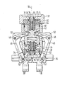
- Figure of the drawing shows a longitudinal section through the embodiment.
- the gripping device shown has a housing 30 which forms the gripper main body and which is sealed off at the top by a cover 32 and at the bottom by an insert body 34.
- the cover 32 is provided with means (not shown in detail) for fastening to the housing 30 and for attaching the device to a manipulator, a machine frame or the like.
- the insert body 34 is connected to two parallel guide strips 36, on which two gripper jaws 38 are mounted so as to be linearly displaceable.
- a one-piece piston 40 is slidably mounted, which delimits a first cylinder space 42 between itself and the cover 32 and a second cylinder space 44 between itself and the insert body 34.
- Some of the pistons 40 are in a recess 41 in the jacket of the piston 40 engaging lever arms articulated by two diametrically opposed angle levers 46, each of which is mounted on a bolt 48 which is fastened to a laterally projecting bracket 50 of the housing 30.
- the other lever arms of the angle lever 46 each engage with a pin 52 in a slot 54 of a gripper jaw 38 which runs parallel to the axis of symmetry 56 of the device.
- the two cylinder spaces 42, 44 are each connected via a line (not shown) to a control device which alternatively connects the cylinder spaces 42, 44 to a pressure medium source and the atmosphere.
- a control device which alternatively connects the cylinder spaces 42, 44 to a pressure medium source and the atmosphere.
- an axially adjustable stop for the piston 40 is formed, with which the piston travel can be limited or adjusted on both sides.
- Each stop has a bushing 58 provided with a threaded bore, which is non-rotatably but axially displaceably mounted in a plastic body 60 or 62, which in turn is fastened in a recess in the cover 32 or in the insert body 34.
- a screw 64 engages in the threaded bore of each bushing 58, the head 66 of which is rotatably mounted in the cover 32 or in the insert body 34 and is sealed by a sealing ring 68.
- a ring collar 70 with a larger diameter is fastened or formed directly next to the head 66 and is provided on the circumference with evenly distributed locking grooves.
- the annular collar 70 is caught between the cover 32 or insert body 34 and the plastic body 60 or 62, as a result of which the screw 64 is held axially immovably on the cover 32 or the insert body 34.
- Each plastic body 60, 62 is provided with a radially extending recess in which a locking ball 72 and a locking spring 74 are arranged and are held immovably by the adjacent end face of the adjacent cover 32 or the insert body 34.
- the detent springs 74 each press the detent balls 72 into one of the detent grooves on the circumference of the collar 70 and hold the screws 64 firmly in the set position.
- each head 66 is provided with a correspondingly shaped recess 76.
- the piston 40 forms a pneumatic drive mechanism with the cylinder spaces 42, 44 and the means for generating and controlled supply of compressed air to the cylinder spaces 42, 44 and ventilation of the cylinder spaces, which is integrated in the gripper main body.
- the piston 40 displaces the gripper jaws 38 via the angle levers 46, as a result of which the desired clamping and releasing processes are brought about.
- both the narrowest and the widest opening of the gripper jaws 38 can be set and the gripper paths can be easily converted to changed conditions.
- the means for adjusting or adjusting these sizes are integrated in the device so that there is a compact design that does not require any additional space.
Landscapes
- Engineering & Computer Science (AREA)
- Robotics (AREA)
- Mechanical Engineering (AREA)
- Manipulator (AREA)
Description
- Die Erfindung geht aus von einer Greifvorrichtung mit einem Greifergrundkörper und einem mit diesem fest verbundenen pneumatischen Antriebsmechanismus, der einen axial verschiebbar gelagerten Kolben hat, der zwischen seinen beiden starren Enden mit mindestens einer Ausnehmung in seinem Mantelumfang versehen ist, in welche die einen Enden von am Greifergrundkörper schwenkbar gelagerten Winkelhebeln eingreifen, die mit ihren anderen Enden, die je in einer die Symmetrieachse des Antriebsmechanismus aufnehmenden Ebene schwenkbar sind, an Greiferbacken angreifen, denen Führungsmittel zugeordnet sind, welche bei einem durch die Winkelhebel hervorgerufenen Verschieben der Greiferbacken quer zur Symmetrieachse ein Kippen der Greiferbacken verhindern.
- Bei einer bekannten Greifvorrichtung dieser Gattung (US-A-3 312 496) sind die Winkelhebel über Drehgelenke mit den Greiferbacken verbunden und die den Greiferbacken zugeordneten Führungsmittel bestehen aus Laschen, die einerseits mit der Greiferbacke und andererseits mit dem Greifergrundkörper jeweils über ein Drehgelenk verbunden sind. Dadurch wird ein Kippen der Greiferbacken vermieden und ein Parallelverschieben sichergestellt. Jedoch erfolgt die Parallelverschiebung der Greiferbacken entlang kreisbogenförmiger Bahnen, so daß sie außer ihrer eigentlichen Spannbewegung auch eine parallel zur Stellgliedachse gerichtete Bewegungskomponente ausführen, was in manchen Fällen unerwünscht oder nachteilig sein kann. Außerdem ergibt sich durch die Vielzahl der Drehgelenke am Greifergrundkörper und an den Greiferbacken ein verhältnismäßig großes Führungsspiel der Greiferbacken, welches sich durch Verschleiß der Drehgelenke insbesondere bei hohen Beanspruchungen noch erhöht. Ferner sind bei der bekannten Vorrichtung keine Mittel zum Einstellen der Öffnungs- und Schließstellung der Greiferbacken vorgesehen.
- Die erfindungsgemäße Anordnung mit den Merkmalen des Hauptanspruchs hat demgegenüber den Vorteil, daß die Greiferbacken exakt geradlinig in Öffnungs- und Schließrichtung bewegt werden und daß die Führungsflächen an den Greiferbacken und den Führungsleisten wesentlich größer ausgebildet werden können als Lagerflächen an Drehgelenken, so daß sich eine verschleißarme und auch für höhere Beanspruchungen gut geeignete Ausführung ergibt. Außerdem ist erreicht, daß die Greiferkraft über einen verhältnismäßig großen Greifbereich hinweg gleichbleibend groß ist und daß die Öffnungs- und Schließstellung der Greiferbacken eingestellt bzw. verstellt werden kann, so daß für den Anwender insbesondere in kritischen Einsatzfällen, z.B. bei begrenzten Freiräumen, Sonderlösungen von Greiferbacken mit eigenen, angepaßten Wegbegrenzungsschultern entfallen und eine Umrüstung auf andere Greiferwege einfach und schnell möglich ist.
- Durch die in den Unteransprüchen aufgeführten Maßnahmen sind vorteilhafte Weiterbildungen der Anordnung nach dem Hauptanspruch möglich.
- Eine kompakte, keinen zusätzlichen Raum beanspruchende und von außen leicht verstellbare Anordnung ergibt sich, wenn der axial verstellbare Anschlag durch eine mit einer Gewindebohrung versehene Buchse gebildet ist, welche unverdrehbar, jedoch verschiebbar in dem den Zylinderraum abschließenden Teil bzw. in einem mit diesem Teil verbunden Kunststoffkörper gelagert ist, und wenn zum axialen Verstellen der Buchse eine in deren Gewindebohrung eingreifende Schraube dient, die ihrerseits axial unverschiebbar an dem den Zylinderraum abschließden Teil gehalten ist.
- Zur Sicherung der eingestellten Lage des Anschlags wird weiter vorgeschlagen, daß die Schraube einen mit Rastnuten am Umfang versehenen Ringbund hat bzw. mit einem derartigen Ringbund verbunden ist, und daß in dem den Zylinderraum abschließenden Teil bzw. in einem mit diesem Teil verbundenen Kunststoffkörper ein Rastglied radial verschiebbar gelagert ist, welches durch eine Feder gegen den Ringbund gedrückt ist.
- Der Gegenstand des Hauptanspruchs ist bis auf die Mittel zum Einstellen der Öffnungs- und Schließstellung der Greiferbacken bereits in der nicht vorveröffentlichten EP-A-0 170 103 enthalten, welche unter Artikel 54 (3) EPÜ fällt und deshalb für die Frage der erfinderischen Tätigkeit nicht von Bedeutung ist.
- Ein Ausführungsbeispiel der Erfindung ist in der Zeichnung dargestellt und in der nachfolgenden Beschreibung näher erläutert. Die einzige
- Figur der Zeichnung zeigt einen Längsschnitt durch das Ausführungsbeispiel.
- Die dargestellte Greifvorrichtung hat ein den Greifergrundkörper bildendes Gehäuse 30, welches oben durch einen Deckel 32 und unten durch einen Einsatzkörper 34 nach außen dicht abgeschlossen ist. Der Deckel 32 ist mit im einzelnen nicht dargestellten Mitteln zum Befestigen am Gehäuse 30 und zum Anbauen der Vorrichtung an einen Manipulator, ein Maschinengestell oder dergleichen versehen. Der Einsatzkörper 34 ist mit zwei parallel nebeneinander laufenden Führungsleisten 36 verbunden, auf denen zwei Greiferbacken 38 linear verschiebbar gelagert sind.
- Im Gehäuse 30 ist ein einstückig ausgeführter Kolben 40 verschiebbar gelagert, der zwischen sich und dem Deckel 32 einen ersten Zylinderraum 42 und zwischen sich und dem Einsatzkörper 34 einen zweiten Zylinderraum 44 begrenzt. Am Kolben 40 sind die einen in eine Ausnehmung 41 im Mantel des Kolbens 40 eingreifenden Helbelarme von zwei sich diametral gegenüberliegenden Winkelhebeln 46 angelenkt, von denen jeder auf einem Bolzen 48 gelagert ist, der an einer seitlich abstehenden Konsole 50 des Gehäuses 30 befestigt ist. Die anderen Hebelarme der Winkelhebel 46 greifen je mit einem Zapfen 52 in einen Schlitz 54 einer Greiferbacke 38 ein, welcher parallel zur Symmetrieachse 56 der Vorrichtung verläuft.
- Die beiden Zylinderräume 42, 44 sind je über eine nicht dargestellte Leitung mit einer Steuereinrichtung verbunden, welche die Zylinderräume 42, 44 alternativ mit einer Druckmittelquelle und der Atmosphäre verbindet. In jedem Zylinderraum 42, 44 ist ein axial verstellbarer Anschlag für den Kolben 40 gebildet, mit welchen der Kolbenweg nach beiden Seiten hin begrenzt bzw. eingestellt werden kann. Jeder Anschlag hat eine mit einer Gewindebohrung versehene Buchse 58, die unverdrehbar, jedoch axial verschiebbar in einem Kunststoffkörper 60 bzw. 62 gelagert ist, der seinerseits in einer Ausnehmung im Deckel 32 bzw, im Einsatzkörper 34 befestigt ist.
- In die Gewindebohrung einer jeden Buchse 58 greift eine Schraube 64 ein, deren Kopf 66 im Deckel 32 bzw. im Einsatzkörper 34 drehbar gelagert und durch einen Dichtring 68 abgedichtet ist. An jeder Schraube 64 ist unmittelbar neben dem Kopf 66 ein im Durchmesser größerer Ringbund 70 befestigt bzw. gebildet, der am Umfang mit gleichmäßig verteilten Rastnuten versehen ist. Der Ringbund 70 ist zwischen Deckel 32 bzw. Einsatzkörper 34 und Kunststoffkörper 60 bzw. 62 gefangen, wodurch die Schraube 64 axial unverschiebbar am Deckel 32 bzw. dem Einsatzkörper 34 gehalten ist.
- Jeder Kunststoffkörper 60,62 ist mit einer radial verlaufenden Randvertiefung versehen, in welcher eine Rastkugel 72 und eine Rastfeder 74 angeordnet und durch die benachbarte Stirnseite des anliegenden Deckels 32 bzw. des Einsatzkörpers 34 unverschiebbar gehalten sind. Die Rastfedern 74 drücken die Rastkugeln 72 je in eine der Rastnuten am Umfang der Ringbunde 70 ein und halten die Schrauben 64 in der eingestellten Lage schüttelsicher fest. Zum Verdrehen der Schrauben mittels eines Steckschlüssels ist jeder Kopf 66 mit einer entsprechend geformten Vertiefung 76 versehen.
- Der Kolben 40 bildet mit den Zylinderräumen 42,44 und den Mitteln zum Erzeugen und gesteuerten Zuführen von Druckluft zu den Zylinderräumen 42, 44 bzw. Entlüften der Zylinderräume einen pneumatischen Antriebsmechanismus, der in den Greifergrundkörper integriert ist. Im Betrieb der Vorrichtung verschiebt der Kolben 40 über die Winkelhebel 46 die Greiferbacken 38, wodurch die gewünschten Spann- und Lösevorgänge hervorgerufen werden. Durch Verdrehen der Schrauben 64 können sowohl die engste als auch die weiteste Öffnung der Greiferbacken 38 eingestellt und die Greiferwege auf veränderte Verhältnisse leicht umgerüstet werden. Die Mittel zum Einstellen bzw. zum Verstellen dieser Größen sind so in die Vorrichtung integriert, daß sich eine kompakte, keinen zusätzlichen Platz benötigte Ausführung ergibt.
Claims (3)
Applications Claiming Priority (3)
| Application Number | Priority Date | Filing Date | Title |
|---|---|---|---|
| DE8423316U DE8423316U1 (de) | 1984-08-04 | 1984-08-04 | Greifvorrichtung |
| DE19853524578 DE3524578A1 (de) | 1984-08-04 | 1985-07-10 | Greifvorrichtung |
| DE3524578 | 1985-07-10 |
Publications (2)
| Publication Number | Publication Date |
|---|---|
| EP0208827A1 EP0208827A1 (de) | 1987-01-21 |
| EP0208827B1 true EP0208827B1 (de) | 1990-06-06 |
Family
ID=25833881
Family Applications (1)
| Application Number | Title | Priority Date | Filing Date |
|---|---|---|---|
| EP86100720A Expired - Lifetime EP0208827B1 (de) | 1984-08-04 | 1986-01-21 | Greifvorrichtung |
Country Status (1)
| Country | Link |
|---|---|
| EP (1) | EP0208827B1 (de) |
Families Citing this family (12)
| Publication number | Priority date | Publication date | Assignee | Title |
|---|---|---|---|---|
| DE3828645A1 (de) * | 1988-08-24 | 1990-03-01 | Bayerische Motoren Werke Ag | Greifvorrichtung |
| JP4126333B2 (ja) * | 1997-02-12 | 2008-07-30 | Smc株式会社 | リニアガイド式エアチャック |
| JP2000343473A (ja) | 1999-06-03 | 2000-12-12 | Smc Corp | 平行開閉チャック |
| JP2018001281A (ja) * | 2016-06-27 | 2018-01-11 | 株式会社デンソーウェーブ | ロボットハンド |
| RU2751612C2 (ru) * | 2017-05-17 | 2021-07-15 | ЭсЭмСи КОРПОРЕЙШН | Пневматический зажимной патрон, снабженный блокировочным механизмом |
| CN108507423A (zh) * | 2017-11-29 | 2018-09-07 | 昆明德澳科技有限公司 | 一种导爆管储料收料装置 |
| CN108858265A (zh) * | 2018-08-10 | 2018-11-23 | 上海交通大学 | 基于人工肌肉的柔性抓手 |
| CN109773805B (zh) * | 2019-02-22 | 2024-05-10 | 中乌先楚核能科技有限公司 | 用于核电站水中狭小空间的夹钳装置 |
| CN113369322B (zh) * | 2021-05-25 | 2023-02-14 | 浙江田中精机股份有限公司 | 一种电机输出轴的卡接筋成型机构 |
| CN113290574B (zh) * | 2021-07-12 | 2025-01-10 | 安图实验仪器(郑州)有限公司 | 用于样本杯自动抓取的夹紧装置 |
| CN113459074A (zh) * | 2021-08-23 | 2021-10-01 | 北京交通大学 | 一种基于可控五杆机构的新型并联操作手 |
| CN113733148B (zh) * | 2021-09-30 | 2022-10-21 | 南京信息职业技术学院 | 一种扭环式抓取机械手 |
Family Cites Families (11)
| Publication number | Priority date | Publication date | Assignee | Title |
|---|---|---|---|---|
| LU36321A1 (de) * | 1957-08-13 | |||
| NL277196A (de) * | 1961-04-14 | |||
| US3370213A (en) * | 1965-04-26 | 1968-02-20 | Programmed & Remote Syst Corp | Force control system for manipulator component |
| US3312496A (en) * | 1965-09-14 | 1967-04-04 | Boutelle Albert | Underwater manipulator |
| US3765545A (en) * | 1971-11-12 | 1973-10-16 | Okuma Machinery Works Ltd | Loader with reversing means |
| US4036374A (en) * | 1975-11-04 | 1977-07-19 | Amc Industries, Inc. | Multi-motion parts handler |
| US4185866A (en) * | 1978-06-21 | 1980-01-29 | Cincinnati Milacron Inc. | External-internal gripper |
| DE2916312C2 (de) * | 1979-04-23 | 1983-10-27 | Zahnradfabrik Friedrichshafen Ag, 7990 Friedrichshafen | Greifzange für Handhabungsgeräte |
| FR2505239A1 (fr) * | 1981-05-06 | 1982-11-12 | Mouton Jean | Bras manipulateur |
| US4522439A (en) * | 1983-08-12 | 1985-06-11 | Walker-Neer Manufacturing Co., Inc. | Automatic pipe elevator |
| DE8423316U1 (de) * | 1984-08-04 | 1986-01-02 | Robert Bosch Gmbh, 7000 Stuttgart | Greifvorrichtung |
-
1986
- 1986-01-21 EP EP86100720A patent/EP0208827B1/de not_active Expired - Lifetime
Also Published As
| Publication number | Publication date |
|---|---|
| EP0208827A1 (de) | 1987-01-21 |
Similar Documents
| Publication | Publication Date | Title |
|---|---|---|
| DE4207576C2 (de) | Greif- und Zuführvorrichtung | |
| DE3133205C2 (de) | Aufeinanderfolgend klemmende und lösende Greifvorrichtung | |
| DE10137198B4 (de) | Klemmvorrichtung | |
| EP0208827B1 (de) | Greifvorrichtung | |
| DE102007031412A1 (de) | Klemmvorrichtung | |
| EP0769353A1 (de) | Kniehebelspannvorrichtung | |
| DE102017202369B3 (de) | Schwenkgelenk für einen Roboterarm und damit ausgestatteter Roboterarm | |
| DE68903791T2 (de) | Ventil-uebersteuerungsmechanismus. | |
| DE102007004186A1 (de) | Radmontage-Industrieroboter und Verfahren zum Betrieb eines Radmontage-Industrieroboters | |
| DE3601225C1 (de) | Wechselkopf fuer eine Werkzeugwechselvorrichtung | |
| DE19749027B4 (de) | Setzgerät | |
| DE3736148A1 (de) | Greifvorrichtung | |
| DE29701730U1 (de) | Kniehebelspannvorrichtung, insbesondere zur Verwendung in Vorrichtungen und Schweißmaschinen des Karosseriebaus der Kfz-Industrie | |
| EP0632221B1 (de) | Drosselventil | |
| DE102017220479B3 (de) | Greifvorrichtung | |
| DE102018119980A1 (de) | Spann- oder Greifeinrichtung | |
| DE19523787C2 (de) | Handhabungswerkzeug für eine Werkzeugmaschine | |
| DE10003961A1 (de) | Spannvorrichtung | |
| EP0170103B1 (de) | Greifvorrichtung | |
| DE3524578A1 (de) | Greifvorrichtung | |
| DE2145643C3 (de) | Spannvorrichtung für Werkzeugmaschinen | |
| DE2816617C2 (de) | Druckluftmotor mit Kolbenschieberventil | |
| DE2626557C3 (de) | Spannvorrichtung, insbesondere Maschinenschraubstock | |
| DE1924402C3 (de) | Teilvorrichtung für Werkzeugmaschinen | |
| DE102019202897A1 (de) | Antriebssystem |
Legal Events
| Date | Code | Title | Description |
|---|---|---|---|
| PUAI | Public reference made under article 153(3) epc to a published international application that has entered the european phase |
Free format text: ORIGINAL CODE: 0009012 |
|
| AK | Designated contracting states |
Kind code of ref document: A1 Designated state(s): CH DE FR GB IT LI |
|
| 17P | Request for examination filed |
Effective date: 19870627 |
|
| 17Q | First examination report despatched |
Effective date: 19890505 |
|
| GRAA | (expected) grant |
Free format text: ORIGINAL CODE: 0009210 |
|
| AK | Designated contracting states |
Kind code of ref document: B1 Designated state(s): CH DE FR GB IT LI |
|
| GBT | Gb: translation of ep patent filed (gb section 77(6)(a)/1977) | ||
| REF | Corresponds to: |
Ref document number: 3671714 Country of ref document: DE Date of ref document: 19900712 |
|
| ET | Fr: translation filed | ||
| ITF | It: translation for a ep patent filed | ||
| PGFP | Annual fee paid to national office [announced via postgrant information from national office to epo] |
Ref country code: GB Payment date: 19910114 Year of fee payment: 6 |
|
| PGFP | Annual fee paid to national office [announced via postgrant information from national office to epo] |
Ref country code: FR Payment date: 19910130 Year of fee payment: 6 |
|
| ITTA | It: last paid annual fee | ||
| PGFP | Annual fee paid to national office [announced via postgrant information from national office to epo] |
Ref country code: DE Payment date: 19910327 Year of fee payment: 6 |
|
| PLBE | No opposition filed within time limit |
Free format text: ORIGINAL CODE: 0009261 |
|
| STAA | Information on the status of an ep patent application or granted ep patent |
Free format text: STATUS: NO OPPOSITION FILED WITHIN TIME LIMIT |
|
| PGFP | Annual fee paid to national office [announced via postgrant information from national office to epo] |
Ref country code: CH Payment date: 19910416 Year of fee payment: 6 |
|
| 26N | No opposition filed | ||
| PG25 | Lapsed in a contracting state [announced via postgrant information from national office to epo] |
Ref country code: GB Effective date: 19920121 |
|
| PG25 | Lapsed in a contracting state [announced via postgrant information from national office to epo] |
Ref country code: LI Effective date: 19920131 Ref country code: CH Effective date: 19920131 |
|
| REG | Reference to a national code |
Ref country code: GB Ref legal event code: PCNP |
|
| PG25 | Lapsed in a contracting state [announced via postgrant information from national office to epo] |
Ref country code: FR Effective date: 19920930 |
|
| REG | Reference to a national code |
Ref country code: CH Ref legal event code: PL |
|
| PG25 | Lapsed in a contracting state [announced via postgrant information from national office to epo] |
Ref country code: DE Effective date: 19921001 |
|
| REG | Reference to a national code |
Ref country code: FR Ref legal event code: ST |
|
| PG25 | Lapsed in a contracting state [announced via postgrant information from national office to epo] |
Ref country code: IT Free format text: LAPSE BECAUSE OF NON-PAYMENT OF DUE FEES;WARNING: LAPSES OF ITALIAN PATENTS WITH EFFECTIVE DATE BEFORE 2007 MAY HAVE OCCURRED AT ANY TIME BEFORE 2007. THE CORRECT EFFECTIVE DATE MAY BE DIFFERENT FROM THE ONE RECORDED. Effective date: 20050121 |