EP0207789A2 - Gerät und Verfahren zur Aufzeichnung vergrösserter Punktmatrix-Zeichen - Google Patents
Gerät und Verfahren zur Aufzeichnung vergrösserter Punktmatrix-Zeichen Download PDFInfo
- Publication number
- EP0207789A2 EP0207789A2 EP86305127A EP86305127A EP0207789A2 EP 0207789 A2 EP0207789 A2 EP 0207789A2 EP 86305127 A EP86305127 A EP 86305127A EP 86305127 A EP86305127 A EP 86305127A EP 0207789 A2 EP0207789 A2 EP 0207789A2
- Authority
- EP
- European Patent Office
- Prior art keywords
- data elements
- binary data
- character
- vertical
- horizontal
- Prior art date
- Legal status (The legal status is an assumption and is not a legal conclusion. Google has not performed a legal analysis and makes no representation as to the accuracy of the status listed.)
- Granted
Links
- 239000011159 matrix material Substances 0.000 title claims abstract description 187
- 238000000034 method Methods 0.000 title claims abstract description 18
- 230000001965 increasing effect Effects 0.000 description 21
- 230000008719 thickening Effects 0.000 description 9
- 238000013500 data storage Methods 0.000 description 8
- 230000000875 corresponding effect Effects 0.000 description 7
- 238000010586 diagram Methods 0.000 description 4
- 238000004519 manufacturing process Methods 0.000 description 4
- 230000004886 head movement Effects 0.000 description 3
- 230000000694 effects Effects 0.000 description 2
- 238000009499 grossing Methods 0.000 description 2
- 230000003116 impacting effect Effects 0.000 description 2
- 229930091051 Arenine Natural products 0.000 description 1
- 238000013459 approach Methods 0.000 description 1
- 238000010420 art technique Methods 0.000 description 1
- 230000001276 controlling effect Effects 0.000 description 1
- 230000002596 correlated effect Effects 0.000 description 1
- 230000006378 damage Effects 0.000 description 1
- 238000006073 displacement reaction Methods 0.000 description 1
- 230000009977 dual effect Effects 0.000 description 1
- 230000002708 enhancing effect Effects 0.000 description 1
- 238000007726 management method Methods 0.000 description 1
- 230000005226 mechanical processes and functions Effects 0.000 description 1
- 230000002250 progressing effect Effects 0.000 description 1
- 230000000135 prohibitive effect Effects 0.000 description 1
- 230000000717 retained effect Effects 0.000 description 1
- 238000012163 sequencing technique Methods 0.000 description 1
- 239000007787 solid Substances 0.000 description 1
Images


Classifications
-
- G—PHYSICS
- G06—COMPUTING; CALCULATING OR COUNTING
- G06K—GRAPHICAL DATA READING; PRESENTATION OF DATA; RECORD CARRIERS; HANDLING RECORD CARRIERS
- G06K15/00—Arrangements for producing a permanent visual presentation of the output data, e.g. computer output printers
- G06K15/02—Arrangements for producing a permanent visual presentation of the output data, e.g. computer output printers using printers
- G06K15/10—Arrangements for producing a permanent visual presentation of the output data, e.g. computer output printers using printers by matrix printers
-
- G—PHYSICS
- G09—EDUCATION; CRYPTOGRAPHY; DISPLAY; ADVERTISING; SEALS
- G09G—ARRANGEMENTS OR CIRCUITS FOR CONTROL OF INDICATING DEVICES USING STATIC MEANS TO PRESENT VARIABLE INFORMATION
- G09G5/00—Control arrangements or circuits for visual indicators common to cathode-ray tube indicators and other visual indicators
- G09G5/22—Control arrangements or circuits for visual indicators common to cathode-ray tube indicators and other visual indicators characterised by the display of characters or indicia using display control signals derived from coded signals representing the characters or indicia, e.g. with a character-code memory
- G09G5/24—Generation of individual character patterns
- G09G5/26—Generation of individual character patterns for modifying the character dimensions, e.g. double width, double height
-
- G—PHYSICS
- G06—COMPUTING; CALCULATING OR COUNTING
- G06K—GRAPHICAL DATA READING; PRESENTATION OF DATA; RECORD CARRIERS; HANDLING RECORD CARRIERS
- G06K2215/00—Arrangements for producing a permanent visual presentation of the output data
- G06K2215/0002—Handling the output data
- G06K2215/004—Generic data transformation
- G06K2215/006—Anti-aliasing raster data
Definitions
- the present invention relates to apparatus and a method for displaying dot matrix characters using stored sets of binary data elements, each representing either a dot or a blank, together with additional binary data elements generated by performing logical operations on the stored data elements in order to display each character in an enlarged size.
- Each character may also be displayed in an enhanced form.
- EP-A-159895 describes apparatus and a method for displaying characters which have been enhanced to a limited extent.
- each character is formed from a matrix of dots and blanks which together define the character.
- the dots are arranged in a matrix of positions and are typically arranged in horizontal rows and vertical columns that are adjacent, parallel, and evenly spaced. The intersections of the rows and columns determine the locations of the dots and blanks, and the dots may overlap, depending upon the spacing between matrix intersections and the dot diameter.
- Each dot or blank is represented in the apparatus by a binary data element with a binary 1 typically representing a dot and a binary 0 representing a blank.
- Data representing at least one entire character set is usually stored in the apparatus, and it includes numerals, upper and lower case letters, punctuation, and other commonly used symbols.
- the quality and size of the character and the speed of displaying may usually be selected as desired, within the capabilities of the display. apparatus and associated data processing apparatus or computer.
- Each type of display apparatus such as a dot matrix printer, electrostatic printer, ink jet printer, cathode-ray tube, etc., has unique physical constraints imposed by its mechanical or electrical capabilities. This usually affects the dot-to-dot spacing between locations in the matrix, as well as the speed at which the dots may be displayed.
- the associated data processing apparatus typically stores the sets of binary data elements defining the shape of the respective characters, performs any necessary logical operations on the stored data to provide the desired size, density or thickness of the displayed character, and governs the physical operations of the printer (or other display apparatus).
- a dot matrix printer it is desirable for a dot matrix printer to print characters in more than one size, and it may also be desirable to print characters in more than one density and thickness. It is also desirable to print at a high speed to provide a high volume output, with a relatively low quality printed character being acceptable, and to alternatively print a relatively high quality character, with a low print speed being acceptable. Printing at a high speed with a low quality printed character is commonly performed when a large volume of output is required, as in a data processing environment. A high speed of printing may be achieved by printing only a comparatively small number of the binary data elements for each character spaced by about one dot width, resulting in the printing of characters of a lower print quality.
- high quality printed characters are preferred in a word processing environment or office environment, as well as the ability to selectively enlarge or enhance all or some of the characters.
- a higher quality character may be achieved by printing a relatively high number of the binary data elements for each character and spacing them by less than one dot width so that they overlap. Lower print speed and volume of output may result, but this is likely to meet the output demands of such an environment.
- An alternative to simply duplicating the stored data to enlarge or enhance a single character is to store all of the binary data representing the multiplicity of sets of all enlarged characters, all improved quality characters, and all of the various combinations thereof.
- a character expanded to 2x, 4x, 8x, etc in size requires 4x, 16x, 64x, etc times the amount o: data storage.
- Such increases in the amount of data storage are usually prohibitive in size and cost.
- Low cost printers that employ inexpensive and relatively simple data processing components do not include the capabilities either to store additional sets of enlarged or enhanced characters, or to process the complex algorithms which have been necessary in the past to enlarge a character and smooth it to maintain its legibility.
- the object of the present invention is to provide an improved apparatus and method for displaying dot matrix characters in an enlarged form.
- the present invention relates to apparatus, for displaying dot matrix characters formed from selected binary data elements each representing either a dot or a blank, of the type which comprises storage means for storing sets of binary data elements, each set defining the shape of a respective character, logic means for performing logical operations on each set of stored binary data elements to generate associated additional binary data elements which can be used to enlarge the size of the respective character selectively, and display means for displaying each character using the associated stored binary data elements and associated additional binary data elements in order to display said character in enlarged size.
- Apparatus in accordance with the present invention is characterised in that the display means uses the generated additional binary data elements together with the stored binary data elements to enlarge the character being displayed in at least one of the vertical, horizontal and diagonal directions by lengthening at least one of the vertical, horizontal and diagonal linear components of the character being displayed along the linear direction thereof.
- the logic means also performs further logical operations on each set of stored binary data elements to generate further associated additional binary data elements which can be used to selectively enhance the character being displayed.
- the display means uses the further generated additional binary data elements to enhance the character being displayed by increasing the density of at least one of the vertical, horizontal and diagonal linear components of the character being displayed along the linear direction thereof.
- the display means uses the further generated additional binary data elements together with the stored binary data elements to enhance the character being displayed by increasing the thickness of at least one of the vertical, horizontal and diagonal linear components of the character being displayed in a direction substantially orthogonal to the linear direction thereof.
- the invention also relates to a method of displaying dot matrix characters in an enlarged form using apparatus as above.
- additional binary data elements are generated from the stored data elements, and dots are printed at selected print positions in the matrix corresponding to the desired character as represented by the combination of the stored and generated data elements.
- the positions for the additional generated binary data elements are selected to enlarge each character by extending the horizontal, vertical and diagonal linear components that together define the character.
- the character may also be enhanced by increasing the density and/or thickening the width of these linear components.
- overlapping dots may be selectively printed along the length of a vertical, diagonal, or horizontal linear component of the character to make it appear darker or more dense, and the components may be selectively widened in a direction generally orthogonal to their linear direction to make them thicker.
- characters may be enlarged, thickened, or have their density changed in all directions, or in one or more of the horizontal, vertical, and diagonal directions, and each may be done independently of the other.
- the data may be processed to enlarge in one direction and enhance in another.
- diagonal refers to any line that is nor either horizontal or vertical.
- direction of designation of a line of binary data elements may be changed as necessary or desirable to suit a particular application.
- the invention is applicable to any data supplied, whether it represents characters, graphics, line drawings, geometrical shapes, etc., since the binary data is considered as a collection of lines.
- the data representing the stored character may be processed to selectively enlarge, thicken, and make more dense less than all of the vertical, horizontal, and diagonal linear components that together form the dot matrix character.
- the additional binary data elements may be combined with the stored binary data elements to thicken the character by positioning the generated binary data elements to thicken the upper portion of the character downwardly and the lower portion of the character upwardly, toward the central portion or middle of the character.
- the character may be differentially enlarged.
- a dot matrix printer typically includes a platen 1 over which a print medium 2 is moved by means of two tractor devices 3, 4.
- the print medium may be, for example, a continuous web of paper having holes 7 parallel to the edges thereof.
- Each tractor device includes a wheel or belt 5 provided with protruding pins 6 on outer surface. The pins 6 engage the holes 7 formed in the web to provide a positive drive.
- the two tractor wheels 5 are mounted on a common shaft 8 which may be rotated as required by a motor 9 to advance the medium over the platen.
- the motor 9 is typically controlled by a print medium controller (not illustrated).
- the printer includes a traversing print head 11 which is mounted on a support 12 extending over the platen 1 so that the medium 2 passes between the platen and the print head 11.
- the print head 11 can be moved along support 12 by motor 13 by way of a belt or a rotating threaded shaft. The combined movement of the paper and movement of the print head allows the print head to reach almost any point on the surface of the medium 2.
- the impacting portion of the print head 11, as illustrated in Fig. 2, is formed in part with a column of seven printing elemencs 14 arranged in a 1 by 7 vertically oriented matrix and supported in a body portion 15.
- the elements 14 are typically wires which can be selectively moved axially by, for example, an electromagnet. Each wire is individually linked to an electromagnet so that it may be individually moved axially as necessary or desirable in timed relation with the movement of the print head 11.
- the printing wires press an inked ribbon onto the medium 2 to perform the printing operation.
- the data defining the characters is provided to the electromagnets controlling the printing wires in a coordinated, time sequence to move them axially as the print head passes through the position at which each character is to be printed.
- the dotted lines 19 - 21 in Fig. 3 help illustrate, respectively, the horizontal, vertical and diagonal linear components of the character. All characters may be defined by such components, with the diagonal component being any linear component that is not horizontal or vertical. These component lines 19-21 are not displayed when the character is printed.
- a full diagonal line is one that falls midway between a horizontal line and a vertical line, i.e. at about a 45° angle.
- a half diagonal line is one that falls midway between a full diagonal line and either a horizontal line or a vertical line, i.e. at about 22-1/2° displaced from either the horizontal line or the vertical line.
- the exact angular displacements may vary.
- print wires 1, 6, and 7 are moved axially to strike the ribbon against the print medium, printing the three dots for column 1, and are then retracted.
- print wires 1, 5, and 7 are moved, and this operation continues as the print head moves through the positions of columns 1 to 5 to print the entire character in 1x size as illustrated.
- each of the printing elements 14 in the print head 11 prints a circular dot which has a diameter of about 1/60 inch, and the spacing between the centres of adjacent elements is substantially equal to the diameter of each dot so that, in the vertical direction, adjacent printed dots will just touch.
- the speed of movement of the print head 11 across the print medium 2 and the frequency of operation of the printing elements 14 are coordinated so that adjacent columns of dots in the horizontal direction have a spacing of 1/60 inch between certres.
- Such a character is illustrated in Fig. 3 and is referred to as a 1x - DP character, meaning 1x size, data processing quality.
- Fig. 4 illustrates the character of Fig. 3 enlarged to a 2x size as was typically done in the prior art by duplicating each of the originally stored dots to the right, down, and down-right. While this enlarges the character satisfactorily in the horizontal and vertical directions, it produces undesirable stair-stepping on diagonals which distorts the character and degrades its legibility. The problem is aggravated by enlargements above 2x. Some smoothing operations have been used in the past to reduce the stair-stepping effect, but they require complex algorithms, additional data processing and data storage capabilities, and are typically very time consuming.
- Figure 5 illustrates the character of Fig. 3 enlarged to the 2x size according to the present invention with the linear components thereof enhanced by being made more dense and thickened.
- Fig. 6 illustrates the character of Fig. 3 enlarged to the 2x size according to the present invent-ion with the linear components thereof thickened but not made more dense.
- Fig. 7 illustrates the character of Fig. 3 enlarged to the 2x size according the present invention with the linear components thereof neither thickened nor made more dense.
- Fig. 8 illustrates the character of Fig. 3 enlarged to the 2x size according to the present invention with the linear components thereof made more dense but not thickened.
- Each of the characters in Figs. 5 - 8 illustrates some of the possible combinations of enlargement and enhancement that are possible with the present invention, and they are discussed in more detail herein.
- Fig. 9 illustrates the logical ones and logical zeros stored in storage device 16 that represent the binary data elements defining the shape of the letter Z.
- the data from the storage device 16 is read out column-by-column, processed as necessary, and the processed data from each column is used to sequentially control the column of printing elements 14 in the print head 11 as it moves across the printing medium.
- the corresponding printing element When a binary 1 is stored in a data storage location, the corresponding printing element is operated to imprint a dot on the printing medium, and when a binary 0 is stored the printing element is not operated.
- the data elements in vertical columns 2, 4, 6, and 8 of the storage device 16 are not used. Thus, the data elements in the columns designated by an asterisk at the top are deleted and only the data elements in the remaining columns are used to print the character.
- Each stored set of binary data elements represents linear components that define the respective character.
- the character is made up of horizontal, vertical, and diagonal components, as illustrated in Figs. 3 - 6.
- each character is enlarged by increasing the length of the linear components that extend in each of the various directions.
- a character may also be thickened by increasing the width of a linear component in a direction generally orthogonal to its length. Compare, for instance, the thickened characters of Figs. 5 and 6 to the non- thickened characters of Figs. 7 and 8.
- the density of the linear components may also be increased to darken the appearance of the character. Compare, for instance, the increased density of the linear components,of the characters of Figs. 5 and 8 with the density of the characters of Figs. 6 and 7.
- the print head When processing data to enlarge a character in the lower quality or data processing mode, such as printing the 2x character of Fig. 6, the print head must make two passes. During the first pass, the upper portion of the character is printed. The paper is then advanced by a distance equal to the height of the column of the dots of the print head and then the second pass is printed to create the lower portion of the character. The print head may move across the print medium at full speed because no overlapping dots are printed to enhance the character by increasing its density or thickening the linear components.
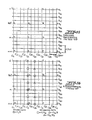
- This reference matrix is then expanded by adding blank binary data elements between the locations of the already stored binary data elements, whether they are a dot or a blank. To determine whether the additional binary data elements are to be converted to a dot, the expanded reference matrix is compared with a predetermined matrix, and, to the extent the expanded reference matrix matches the predetermined matrix, the additional binary data elements are converted to dots. The data is then printed out:
- the reference matrix of Fig. 10 has been expanded for 2x enlargement in the data processing mode by adding a single row midway between each of the existing rows, the added rows being designated Rlb, R2b, R3b, etc., and the existing rows being designated R1, R2, R3, etc. Similarly, a column is added midway between each of the existing columns, the added columns being designated Clb, C2b, C3b, etc., and the existing columns being designated C1, C2, C3, etc.
- the spacing between each of the original rows and added rows is one dot width, and the spacing between each of the original columns and added columns is one-half dot width.
- the positions at the intersections of the added Rb rows with the existing C columns and added Cb columns, and the intersections of the added Cb columns with the existing R rows and added Rb rows represent the positions of the additional blank binary data elements which may later be converted to dots.
- the relative positions of the lettered locations A-D, G-K, M-N, P for the stored binary data elements remain the same, with the spacing between them being increased.
- Figure 12 illustrates the expanded reference matrix of Fig. 11 with locations A, B, C, and D defining a predetermined matrix to determine which, if any, of certain ones of the additional binary data elements are to be converted to a dot.
- the logical operations to perform the comparison are performed using the columns of the matrices.
- the stored binary data elements in the reference matrix are identified by specifying their relative positions with respect to an arbitrarily selected reference row.
- the reference row of Fig. 12 is row R2, and the remaining rows are correlated to the reference row by logically shifting row R1 down one position (d); row R3 up-one position (u) and row R4 up two positions (uu).
- row R2 being specified as the reference row in Fig. 12, .: the data positions A-D, G-K, M-N, P are designated as follows:
- portions of the expanded reference matrix are compared with a predetermined matrix (Fig. 12) to convert certain of the additional blank binary data elements to dots.
- a predetermined matrix Fig. 12
- the expanded reference matrix is first compared with a predetermined matrix to determine if that binary data element is part of a linear component of the character which must be enlarged in the horizontal direction.
- the predetermined matrix is represented by the following: This expression states, using Boolean logic, that the binary data element at position C2b, R2b is converted to a dot (binary 1) if the data elements .
- positions A and D are blanks (binary 0) and the data elements in positions B and C are dots, or if the data elements in positions A and D are dots and the data elements in positions 8 and C are blanks. Otherwise it remains a blank, unless another predetermined matrix causes it to be converted to a dot. Applying this predetermined matrix to the expanded reference matrix of Fig. 12, if positions A and B contain dots and positions C and D contain blanks, the data element in position C2b, R2b remains a blank.
- the predetermined matrices to determine whether the additional binary data elements for the C(i)b columns (Clb, C2b, C3b, etc.) are to be converted to dots are represented as follows: As noted earlier, these predetermined matrices convert those aaditional blank binary data elements to dots which are used to enlarge the character in the horizontal direction.
- the binary data elements added to all of the positions C,Rb are compared with another predetermined matrix.
- the expanded reference matrix is compared to a predetermined matrix represented by the following:
- the status for all of the additional binary data elements in the C2 column for all of the Rb positions is represented in column form by the following:
- This predetermined matrix is used to thicken the upper portion of the character towards the middle, which improves the symmetry and appearance of the enlarged character. More specifically, thickness is added to horizontal lines in the upper portio of the character by converting to dots those additional binary data elements that are generally located beneath a dot representing the stored character.
- the predetermined matrix for determining whether the additional binary data elements should be converted to dots to be used to enlargea character in the vertical direction and add vertical thickness toward the.middle are represented as follows:
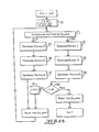
- Fig. 13 is a flow chart representing the logical operations performed in accordance with the invention to print characters that are doubled in size (2x) and of a data processing quality (DP).
- Each enlarged character is derived from the binary data elements stored in memory device 16 for a normal size (1 x) character to provide the type of character illustrated in Fig. 6.
- the sequencing parameters which cause the program to treat each column C(01), C(02)r C(03), etc. of the expanded reference matrix are set to their initial values.
- the type of column of the expanded reference matrix (e.g. Figs. 12, 13) is determined as either column C, representing both stored and additional binary data elements, or column Cb, which represents only additional binary data elements.
- the columns of the expanded reference matrix are then compared with the Matrices 1 - 6 to determine whether or not the additional binary data elements should be converted to dots or remain as blanks, as represented by the steps 22 - 27. This process may be repeated on a column-by-column basis for each of the K-columns, as determined by a counting loop designated at steps 30, 31. When all K columns have been printed, the routine ends.
- the method described thus far results in the display of characters that have been enlarged and thickened, while the density has not been increased, as illustrated in Fig. 6.
- the dot density of the characters be increased so that the lines of the character appear solid with no distortions, as illustrated in Fig. 5. This is done using logical operations similar to those used with the data processing mode character.
- the stored sets of binary data elements used in the word processing mode are the same stored binary data elements used in the data processing mode, as illustrated in Fig. 9. Thus, only a single set of binary data elements, with each set defining the shape of a respective character, need to be stored to print characters of varying sizes, density, and thickness.
- an enlarged word processing quality character may be printed by generating additional binary data elements to increase the length of the vertical, diagonal and horizontal linear components'thereof, increasing the thickness of the vertical, diagonal and horizontal linear components in a direction orthogonal to the linear direction thereof, and increasing the density of the vertical and diagonal linear components thereof.
- the horizontal linear components are stored with an increased density. To increase the character beyond the 2x size, it is necessary to further increase the length, thickness, and density of all the linear components thereof.
- the method for producing higher quality characters suitable for word processing increases the density of the character enlarged for the lower quality or data processing mode by converting to dots additional binary data elements in positions that are between binary data elements for the data processing mode character. This, in essence, fills in the gaps between the dots of the character along the length of each of the linear components making up the character.
- the increased density typically necessitates a second pass of the print head.
- the data printed during the second pass is not the same as the data printed during the first pass.
- the printing speed is reduced to one-half the data processing mode speed to permit the additional dots to be printed between the dots of the data processing character in the horizontal direction.
- the paper is advanced by a distance equal to one-half the diameter of a dot, and another pass of the print head places the additional dots between the existing dots.
- the character consists of two portions, upper and lower, and each portion requires two passes of the print head to provide the desired dot density.
- the second pass refers to the pass that places dots between existing dots in the vertical direction after the paper has been advanced by one-half the diameter of a dot.
- Figure 14 illustrates diagrammatically a reference matrix for the 1x size for use in enlarging a character in the word processing or fully enhanced mode.
- the sixteen matrix positions A - N, P - Q defined by the intersections of the R rows and C columns correspond to the stored binary data elements defining the shape of the character.
- the horizontal rows R1 - R4 are each vertically spaced by one dot width, and the vertical columns C1 - C4 are each spaced by one-half dot width.
- the matrix is similar to that illustrated in Figure 10, with an additional column C4 added to the matrix to provide a total of 16 intersections or matrix positions representing the binary data elements.
- Figure 15 illustrates diagrammatically an expansion of the reference matrix of Fig. 14 for the word processing mode with columns Ca, Cb, and Cc added between each of the existing columns C1, C2, C3, C4, which represent the binary data elements stored in memory element 16.
- rows Ra, Rb, and Rc are added between each of the existing rows R1, R2, R3, and R4, which represent the binary data elements stored in memory device 16.
- the intersections of the added columns with the added rows and existing rows, and the intersections of the added rows with the existing columns together represent the fifteen blank binary data elements that have been added to the defined reference matrix for each stored binary data element for use in enlarging the character to a 2x size.
- the spacing between each of the rows e.g. R3c and R4) is one-half dot width
- the spacing between each of the columns e.g. C1 and C1c
- This spacing provides the desired dot overlap in all directions to achieve a higher density character.
- the individual stored binary data elements are represented by the letters A - N, P - Q, and may be expressed using columns to specify their relative position to a reference row, such as row R2.
- the binary data elements in row R1 may be identified with respect to row R2 by logically shifting the column containing the binary data elements in row R1 down one position (d).
- the binary data elements in rows R3 and R4 may be specified with respect to the reference row R2 by logically shifting the column up one position (u) or up two positions (uu), respectively.
- the data positions A - N, P - Q are designated as follows with respect to reference row R2 of Fig. 15:
- characters printed in the word processing mode are printed in two sets of two passes of the print head.
- the first set prints the upper-portion of the character and the second set prints the lower portion of the character.
- the binary data elements in the R rows R1, R2, R3, etc are printed out using the odd print head wires (1, 3, 5, 7) in the print head 11 and the binary data elements in the Rb rows Rbl, Rb2, Rb3, etc are printed out using the even numbered print head wires (2, 4, 6) of the print head.
- the data elements in the Ra rows Rla, R2a, R3a, etc are printed out using the odd print head wires and the data elements in the Rc rows R1c, R2c, R3c, etc are printed out using the even wires.
- the expanded reference matrix is compared with a predetermined matrix, as noted earlier, and selected ones of the additional binary data elements are converted from blanks to dots when the reference matrix matches the predetermined matrix.
- the binary data elements at locations C, R i.e. those designed by letters A - N, P - Q, are obtained from the stored data.
- the status of each of the additional binary data elements at locations C,Rb; Cb,R; and Cb,Rb, as illustrated in Fig. 16, is determined by comparison with the predetermined matrices described below.
- the status of the additional blank binary data element at the intersection of column C2 and row R2b is determined by comparing the expanded reference matrix with a predetermined matrix represented by the following:
- the status of each of the additional binary elements for all of the intersections of the C2 column and Rb rows may be determined by comparing the expanded reference matrix with a predetermined matrix represented by the following:
- the status of each of the additional binary data elements for all columns C1, C2, C3, etc. of the expanded reference matrix for use in enlarging the character in the vertical direction may be determined by comparison with a predetermined matrix represented by the following:
- the additional blank binary data elements at locations Cb,R and Cb,Rb are compared with another set of predetermined matrices to determine which binary data elements should be converted to dots.
- the binary data elements at the intersection of column C2b and row R2 are compared with a predetermined matrix represented by the following: The status of each of the additional binary data elements for all of the intersections of column C2b and the R rows, R1, R2, R3, etc.
- the status of the additional binary data element located at the intersection of column C2b and row R2b is determined by comparison with the predetermined matrix represented by the following: Combining the above matrices, the status of each of the-additional binary data elements located at the intersections of the columns C2b, and Rb rows Rlb, R2b, R3b, etc.
- the status of each of the blank additional binary data elements for all of the Cb columns, Clb, C2b, C3b, etc., whichare used to enlarge the character in the horizontal direction and maintain its high density in the horizontal direction may be determined by comparing the expanded reference matrix with a predetermined matrix represented by the following: where The additional binary data elements for the Ca and Cc columns remain blanks for enlargement to the 2x size.
- the expanded reference matrix is compared with predetermined matrices represented by the following:
- Figure 17 illustrates the print out of the combination of the generated additional binary data elements and stored binary data elements after making two of the four passes for an exemplary word processing quality character enlarged to 2x size as displayed by a dot matrix printer.
- the flow chart of Fig. 19 illustrates the logical operations just discussed.
- the status of the additional binary data element at the intersection of column C2 and row R2a of the expanded reference matrix is determined by comparison with a predetermined matrix represented by the following: The status of each of the additional binary data elements at the intersections of column C2 and the Ra rows Rla, R2a, R 3 a , etc.
- the status of the additional binary data element at the intersection of column C2 and row R2c of the expanded reference matrix is determined by comparison with a predetermined matrix represented by the following:
- the status of each the additional binary data elements at the intersections of column C2 and the Rc rows R1c, R2c, R3c, etc. of the expanded reference matrix is determined by comparison with a predetermined matrix represented by the following:
- the status of each of the additional binary data elements for all columns C1, C2, C3, etc. at the intersections with the Ra and Rc rows, which thicken the character in the vertical direction and increase the density in the vertical direction is determined by comparison with a predetermined matrix represented by the following:
- Matrix 11 serves a dual role by thickening the character toward the central portion or middle to improve character symmetry. It adds thickness downwardly to the horizontal lines in the upper portion of the character (i.e. the upper three rows of a seven row character) by converting to a dot those additional binary data elements at locations generally below the corresponding binary data element locations representing the stored character. However, the horizontal lines in the lower portion of the character (i.e. the lower four rows of a seven row character) are thickened upwardly by converting to a dot the additional binary data elements at locations generally above the corresponding binary data element locations representing the stored character. (See the later discussion in connection with Figs. 20, 21 for more detail.) This is accomplished by exchanging the data between the odd and even wires of the print head as determined by predetermined Matrix 11 and illustrated in Figs. 19A and 19B.
- the status of the additional blank binary data element at the intersection of column C2a and row R2a of the expanded reference matrix is determined by comparison with a predetermined matrix represented by the following: The status of each of the additional binary data elements at the intersections of column C 2a and the Ra rows Rla, R2a, R3a, etc. of the expanded reference matrix i s determined by comparison with a predetermined matrix represented by the following: The status of the additional binary data element at the intersection of column C2a and row R2c of the expanded reference matrix is determined by comparison with a predetermined matrix represented by the following: The status of each of the additional binary data elements at the intersections of column C2a and the Rc rows Rlc, R2c, R3c, etc.
- the status of each of the blank additional binary data elements at the intersections of all Ca columns Cla, C2a, C3a, etc. of the expanded reference matrix, which increase the density of the half diagonal linear components, is determined by comparison with a predetermined matrix represented by the following:
- the status of the additional binary data element at the intersection of column C2b, and row R2a of the expanded reference matrix is determined by comparison with apredetermined matrix represented by the following: The status of each of theadditional binary data elements at the intersections of column C2b and the Ra rows Rla, R2a, R3a, etc.
- the status of the additional binarydata element at the intersection of column C2b and row R2c of the expanded reference matrix is determined by comparison with a predetermined matrix represented by the following:
- the status of each of the additional binary data elements at the intersections of column C2b and the Rc rows Rlc, R2c, R3c, etc. of the expanded reference matrix is determined by comparison with a predetermined matrix represented by the following:
- the status of each of che blank additional binary data elements for all Cb columns Clb, C2b, C3b, etc. to enhance the full diagonal linear components of the expanded reference matrix is determined by comparison with a predetermined matrix represented by the following:
- the status of the additional blank binary data element at the intersection of column C2c and row R2a of the expanded reference matrix is determined by comparison with a. predetermined matrix represented by the following: The status of each of the additional binary data elements at the intersections of column C2c and the Ra rows R1a, R2a, R3a, etc. of the expanded reference matrix is determined by comparison with a predetermined matrix represented by the following: The status of the additional binary data element at the intersection of column C2c and row R2c of the expanded reference matrix is determined by comparison with a predetermined matrix represented by the following: The status of each of the additional binary data elements at the intersections of column C2c and the Rc rows Rlc, R2c, R3c, etc.
- the status of each of the additional blank binary data elements for all Cc columns Clc, C2c, C3c, etc. for increasing the density of other half diagonals of the expanded reference matrix are determined by com- parisonwith a predetermined matrix represented by the following:
- each binary data element of the expanded reference matrix as determined by comparison with Matrices 11 to 14 is duplicated two matrix positions to the right.
- the status of each of these binary data elements is determined by comparison with predetermined matrices represented by the following:
- Figures 19A, 19B together from a flow chart representing the logical operations to be performed in accordance with the invention to print characters that are doubled in size and enhanced in the word processing mode (2x, WP) as illustrated in Fig. 5.
- the data representing the column positions at the left and right of the stored matrix and the data therein are initialised and set to zero.
- the pass of the print head is determined as either first or second.
- the type of column is determined as C, Ca, Cb, or Cc for the column-by-column determination of which additional binary data elements are to be converted from blanks to dots.
- the thickening of the horizontal line components of a dot matrix character as practised in the prior art is compared with the thickening towards the middle as in the present invention.
- the horizontal components of characters were thickened vertically by printing all horizontal lines a second time one half dot lower than they were printed the first time, and this was usually done using the same data for both the first and second passes.
- each of the dots, such as 50, 51 was duplicated one half position lower as at posaons 53. While this is generally acceptable for the upper portions of the character, it is undesirable for dots extending to the baseline because the character loses it symmetry and extends below the baseline as illustrated by the thickening of dots 54, 55 by dots 56, 57.
- the binary data elements for the character are logically processed to print a character that is vertically thickened towards the middle, which preserves the baseline of the original character.
- the horizontal linear components in the upper portion of the character such as represented by dots 61, 62, are thickened by converting to dots those binary data elements 63, 64 immediately below the corresponding binary data elements 61, 62.
- the binary data elements immediately above the corresponding stored binary data elements are converted to dots.
- Those binary data elements in the central portion of the character may be thickened upwardly or downwardly as necessary or desirable.
- the method of actually displaying such characters was described earlier in connection with enlargement in the word processing mode, second pass printing, Matrix 11. Apparatus for displaying such characters is described in connection with Figs. 1, 2, 3, and 24.
- logical operations are performed on the set of stored binary data elements to generate additional binary data elements that enlarge the character and increase its density but not its thickness.
- sets of stored binary data elements which define characters having a relatively high density in the horizontal direction and a relatively low density in the vertical and diagonal directions (i.e. as in Fig. 9)
- the logical operations increase the length of the vertical, diagonal and horizontal linear components thereof, maintain the thickness of the vertical, diagonal, and horizontal linear components in the direction generally orthogonal to their linear direction, and selectively increase the density of the vertical and diagonal linear components while maintaining the high density of the horizontal linear components.
- logical operations are performed on the set of stored binary data elements to generate additional binary data elements that enlarge the character without thickening or increasing the density of the linear components.
- sets of stored binary data elements which define characters having a relatively high density in the horizontal direction and a relatively low density in the vertical and diagonal directions, such characters are obtained by following the method for producing a character expanded to the 2x size in the data processing mode, as described earlier, but using only predetermined Matrix 1 and substituting for Matrix 2 the Matrix 2A as represented below. where The flow chart representing this sequence of operations is shown in Fig. 23.
- Still other logical operations may be performed to display a character where some but not all of the linear components are thickened or have an increased density.
- the character may be enlarged with the horizontal components being enhanced by thickening and increasing the density thereof, while the diagonal and vertical components are not enhanced and are of the data processing quality.
- sets of stored binary data elements which define characters having a relatively high density in the horizontal direction and a relatively low density in the vertical and diagonal directions, such characters are obtained by following the method for producing a character expanded to the 2x size in the word processing mode (Fig. 19), but omitting the logical operations of making comparisons with Matrices 15, 16, 17 and 18.
- logical operations may be performed on the stored binary data elements to ultimately display characters where the horizontal linear components are of a data processing quality and the diagonal and vertical components are of an enhanced word processing quality.
- Matrix 11A below for Matrix 11, omitting the logical operations represented by Matrices 19, 20, 21, and 22, and eliminating the step of exchanging the data for the even and odd wires when printing the second pass for the lower portion of the character.
- Logical operations may be performed on a set of the stored binary data elements to display a character having linear components where the horizontal components are of a word processing quality and the vertical and diagonal components are of a thickened word processing quality, meaning that they have the increased density of the word processing quality characters but have been thickened more than usual to be two dots thick, rather than one and one-half dots thick.
- Fig. 19 it is modified by replacing Matrices 15, 16, 17, and 18 with Matrices 15A, 16A, 17A, and 18A, respectively, as set forth below:
- Logical operations may be performed on a set of the stored binary data elements to display a character having linear components wherein the vertical and diagonal lines are of the word processing quality, and the horizontal lines are of a word processing quality that has been thickened. For instance, the horizontal lines are two dots wide, while the other lines are one and a half dots wide, with the dots overlapping to provide the increased density.
- the flow chart of Fig. 19 it is modified to display such a character by replacing Matrices 7 and 8 with Matrices 7A and 8A, respectively, as represented by the following:
- Logical operations may also be performed on a set of the stored binary data elements to display a character where all of the component lines are of the enhanced word processing quality and have been thickened more than usual.
- FIGs. 19A and 19B it is modified to display such a character by replacing Matrices 7, 8, 15, 16, 17, and 18 with Matrices 7A, 8A, 15A, 16A, 17A, and 18A, respectively, as represented above.
- Similar matrices may be used to selectively add or delete varying amounts of thickness to the various vertical, horizontal, and diagonal components of enlarged characters by changing the logical operations performed on the stored data.
- the character may be enlarged differentially in varying degrees, i.e. to provide characters that are enlarged to a 2x size in the vertical direction but retained in their usual 1x size in the horizontal direction. This allows one to provide varying pitch to select between, for example, 10 characters per inch or 12 characters per inch.
- Figure 24 illustrates diagrammatically apparatus for displaying enlarged dot matrix characters that may be selectively enlarged or-#selectively thickened, or selectively made more dense, in accordance with the present invention.
- the circuitry includes a control unit 71, a character data storage element 72, a logic unit 73, a print medium controller 74 connected to the tractor motor 9, a print head movement controller 76 attached to the print head motor 13, and a print head actuator 75 connected to the print head 15 to control the actuation of each of the individual print wires 1'4.
- the sets of binary data elements are stored in the character data storage means 72, which includes a plurality of storage devices 16, as referred to in Fig. 9; Binary data representing either a dot or a blank in a matrix of positions arranged in horizontal rows and vertical columns is stored in each of the storage devices 16, and together the stored data represents a character.
- the logic unit 73 includes means for performing logical operations on the selected sets of binary data elements representing the various characters. It may, among other things, address the appropriate data representing the desired character, read out the data representing the desired character, define a reference matrix for each.character, expand the reference matrix by adding blank binary data elements, compare selected portions of the expanded reference matrix with a predetermined matrix, and convert to dots those additional binary data elements that match the predetermined matrix. As instructed by the control unit, this will result in characters which are selectively enlarged, thickened, and made more dense as desired by the operator of the printer.
- the control unit 71 includes means governing the data processing and mechanical functions of the printer, coordinates their respective operations, and may further communicate with a host computer. Management of the data processing may include control of the character data storage means 72 and the logic unit 73. Control of the mechanical operation of the printer may include control of the print medium or paper, print head movement, and the actuation of the wires in the print head.
- the print medium controller 74 provides signals to the motor 9 to control the movement of the print medium 2 over the platen and past the print head.
- the print head movement controller 76 provides signals to the print head motor 13 to control the translational movement of the print head across the print medium 2.
- the print head actuator 75 provides signals to actuate the individual printing elements 14 of the print head 11 under control of signals from the control unit 71 and in accordance with the data signals from the data storage unit 72 and from logic unit 73.
- the control unit 71 typically coordinates the flow of data to the print head actuator with the physical movement of the print head.
- the invention has been described with respect to a specific dot matrix printer, and in connection with 2x enlargement, it is to be understood that it may be used in connection with-any device that will display a dot matrix character of any size.
- the specific embodiment generally describes left to right printing.
- right to left printing is possible by simply starting the operations at the right end of the matrix and progressing towards the left.
Landscapes
- Engineering & Computer Science (AREA)
- Physics & Mathematics (AREA)
- General Physics & Mathematics (AREA)
- Theoretical Computer Science (AREA)
- Mathematical Physics (AREA)
- General Engineering & Computer Science (AREA)
- Computer Hardware Design (AREA)
- Controls And Circuits For Display Device (AREA)
- Dot-Matrix Printers And Others (AREA)
Applications Claiming Priority (2)
| Application Number | Priority Date | Filing Date | Title |
|---|---|---|---|
| US06/752,176 US4712102A (en) | 1985-01-29 | 1985-07-03 | Method and apparatus for displaying enlarged or enhanced dot matrix characters |
| US752176 | 1985-07-03 |
Publications (3)
| Publication Number | Publication Date |
|---|---|
| EP0207789A2 true EP0207789A2 (de) | 1987-01-07 |
| EP0207789A3 EP0207789A3 (en) | 1989-06-14 |
| EP0207789B1 EP0207789B1 (de) | 1993-03-31 |
Family
ID=25025220
Family Applications (1)
| Application Number | Title | Priority Date | Filing Date |
|---|---|---|---|
| EP86305127A Expired - Lifetime EP0207789B1 (de) | 1985-07-03 | 1986-07-02 | Gerät und Verfahren zur Aufzeichnung vergrösserter Punktmatrix-Zeichen |
Country Status (7)
| Country | Link |
|---|---|
| US (1) | US4712102A (de) |
| EP (1) | EP0207789B1 (de) |
| JP (1) | JPS629961A (de) |
| BR (1) | BR8602936A (de) |
| CA (1) | CA1249085A (de) |
| DE (1) | DE3688154T2 (de) |
| ES (1) | ES8801741A1 (de) |
Cited By (2)
| Publication number | Priority date | Publication date | Assignee | Title |
|---|---|---|---|---|
| GB2243808A (en) * | 1990-05-12 | 1991-11-13 | Brother Ind Ltd | Deriving draft quality dot patterns from letter quality dot patterns in matrix printers |
| EP0533049A2 (de) * | 1991-09-18 | 1993-03-24 | Seiko Epson Corporation | Drucker zum Drucken von fetten Buchstaben |
Families Citing this family (21)
| Publication number | Priority date | Publication date | Assignee | Title |
|---|---|---|---|---|
| JPS6246664A (ja) * | 1985-08-23 | 1987-02-28 | Sharp Corp | 拡大装飾文字出力装置 |
| US6697070B1 (en) | 1985-09-13 | 2004-02-24 | Renesas Technology Corporation | Graphic processing system |
| JPH0762794B2 (ja) * | 1985-09-13 | 1995-07-05 | 株式会社日立製作所 | グラフイツク表示装置 |
| US4809341A (en) * | 1986-07-18 | 1989-02-28 | Fujitsu Limited | Test method and apparatus for a reticle or mask pattern used in semiconductor device fabrication |
| US4914426A (en) * | 1987-08-04 | 1990-04-03 | High Resolution Sciences, Inc. | Sinusoidally modulated dot-matrix data display system |
| JPH01174463A (ja) * | 1987-12-28 | 1989-07-11 | Sharp Corp | ドットパターン補正方法 |
| JP3016515B2 (ja) * | 1989-01-31 | 2000-03-06 | キヤノン株式会社 | 文字処理装置および方法 |
| JP2952915B2 (ja) * | 1989-03-03 | 1999-09-27 | セイコーエプソン株式会社 | ドットパターンデータ発生装置 |
| JPH02232690A (ja) * | 1989-03-04 | 1990-09-14 | Brother Ind Ltd | データ変換装置 |
| US5200740A (en) * | 1989-08-01 | 1993-04-06 | Adobe Systems Incorporated | Dropout-free center point fill method for displaying characters |
| US5150108A (en) * | 1989-12-27 | 1992-09-22 | Xerox Corporation | Method for slanting a generic font format while inserting corrective pixels to improve print quality |
| JP2844575B2 (ja) * | 1990-04-19 | 1999-01-06 | キヤノン株式会社 | 印刷装置 |
| EP0497537B1 (de) * | 1991-02-01 | 1997-07-16 | Canon Kabushiki Kaisha | Bildverarbeitungsverfahren und -gerät |
| JP2699035B2 (ja) * | 1991-09-03 | 1998-01-19 | 株式会社ピーエフユー | インパクト・ドット・プリンタおよび印字方法 |
| JPH05314250A (ja) * | 1992-05-11 | 1993-11-26 | Fuji Xerox Co Ltd | 拡大画像の平滑方法及び装置 |
| EP0651571B1 (de) * | 1993-11-02 | 2000-03-15 | Texas Instruments Incorporated | Vorrichtung und Verfahren für graphische Daten für Fernsehempfänger |
| GB2309807B (en) * | 1996-02-02 | 2000-05-31 | Esselte Nv | Printing apparatus |
| FI973041A (fi) | 1997-07-18 | 1999-01-19 | Nokia Mobile Phones Ltd | Laite ja menetelmä kuvan näyttämiseksi |
| US6256650B1 (en) * | 1998-05-18 | 2001-07-03 | Microsoft Corporation | Method and system for automatically causing editable text to substantially occupy a text frame |
| US7348983B1 (en) * | 2001-06-22 | 2008-03-25 | Intel Corporation | Method and apparatus for text image stretching |
| US8487936B2 (en) * | 2007-05-30 | 2013-07-16 | Kyocera Corporation | Portable electronic device and character display method for the same |
Citations (1)
| Publication number | Priority date | Publication date | Assignee | Title |
|---|---|---|---|---|
| EP0159895A2 (de) | 1984-04-20 | 1985-10-30 | International Business Machines Corporation | Drucker zum Drucken von Zeichen in zwei alternativen Druckqualitäten |
Family Cites Families (24)
| Publication number | Priority date | Publication date | Assignee | Title |
|---|---|---|---|---|
| NL283649A (de) * | 1961-12-29 | |||
| US3588872A (en) * | 1968-03-04 | 1971-06-28 | Harris Intertype Corp | Point size,computation and exposure control device for a character display apparatus |
| US3546681A (en) * | 1969-01-30 | 1970-12-08 | Rca Corp | Programmed method for manipulating electronic fonts in electronic photocomposition systems |
| DE2213953C3 (de) * | 1972-03-22 | 1978-04-27 | Siemens Ag, 1000 Berlin Und 8000 Muenchen | Schaltungsanordnung zum Darstellen von Zeichen auf dem Bildschirm eines Sichtgerätes |
| US3868673A (en) * | 1973-08-14 | 1975-02-25 | Teletype Corp | Display apparatus including character enhancement |
| US3911420A (en) * | 1973-11-23 | 1975-10-07 | Xerox Corp | Display system including a high resolution character generator |
| US3903517A (en) * | 1974-02-26 | 1975-09-02 | Cummins Allison Corp | Dual density display |
| JPS52107723A (en) * | 1974-12-28 | 1977-09-09 | Seikosha Kk | Device for forming picture |
| JPS526419A (en) * | 1975-07-07 | 1977-01-18 | Fuji Xerox Co Ltd | Dot matrix convertor |
| JPS5942309B2 (ja) * | 1975-09-12 | 1984-10-13 | 株式会社精工舎 | 画像形成方法 |
| US4107662A (en) * | 1976-02-17 | 1978-08-15 | Hitachi, Ltd. | Character generator for visual display devices |
| US4081799A (en) * | 1976-03-03 | 1978-03-28 | Sperry Rand Corporation | Character generation system for a visual display terminal |
| US4242678A (en) * | 1978-07-17 | 1980-12-30 | Dennison Manufacturing Company | Variable size character generation using neighborhood-derived shapes |
| US4290064A (en) * | 1979-08-03 | 1981-09-15 | Harris Data Communications, Inc. | Video display of images with improved video enhancements thereto |
| US4367533A (en) * | 1980-08-25 | 1983-01-04 | Xerox Corporation | Image bit structuring apparatus and method |
| US4358788A (en) * | 1981-02-27 | 1982-11-09 | Rca Corporation | Legibility for alpha-mosaic characters |
| JPS57187257A (en) * | 1981-05-15 | 1982-11-17 | Fuji Xerox Co Ltd | Printing system |
| JPS583880A (ja) * | 1981-06-30 | 1983-01-10 | Seikosha Co Ltd | クロスハンマ式ドツトプリンタ |
| US4450483A (en) * | 1981-09-02 | 1984-05-22 | Westinghouse Electric Corp. | Circuit for improving the quality of digitized line images |
| US4428284A (en) * | 1981-12-28 | 1984-01-31 | International Business Machines Corp. | Band and hammer dot matrix printer |
| JPS5942971A (ja) * | 1982-09-03 | 1984-03-09 | Hitachi Ltd | 拡大印字制御方式 |
| US4508463A (en) * | 1982-11-01 | 1985-04-02 | Wang Laboratories, Inc. | High density dot matrix printer |
| US4555701A (en) * | 1982-12-27 | 1985-11-26 | International Business Machines Corporation | Legibility enhancement for alphanumeric displays |
| JPS59162984A (ja) * | 1983-05-23 | 1984-09-13 | セイレイ工業株式会社 | 円筒形選別機 |
-
1985
- 1985-07-03 US US06/752,176 patent/US4712102A/en not_active Expired - Lifetime
-
1986
- 1986-06-03 CA CA000510694A patent/CA1249085A/en not_active Expired
- 1986-06-18 JP JP61140395A patent/JPS629961A/ja active Granted
- 1986-06-19 ES ES556260A patent/ES8801741A1/es not_active Expired
- 1986-06-25 BR BR8602936A patent/BR8602936A/pt unknown
- 1986-07-02 EP EP86305127A patent/EP0207789B1/de not_active Expired - Lifetime
- 1986-07-02 DE DE86305127T patent/DE3688154T2/de not_active Expired - Fee Related
Patent Citations (1)
| Publication number | Priority date | Publication date | Assignee | Title |
|---|---|---|---|---|
| EP0159895A2 (de) | 1984-04-20 | 1985-10-30 | International Business Machines Corporation | Drucker zum Drucken von Zeichen in zwei alternativen Druckqualitäten |
Cited By (4)
| Publication number | Priority date | Publication date | Assignee | Title |
|---|---|---|---|---|
| GB2243808A (en) * | 1990-05-12 | 1991-11-13 | Brother Ind Ltd | Deriving draft quality dot patterns from letter quality dot patterns in matrix printers |
| GB2243808B (en) * | 1990-05-12 | 1994-10-05 | Brother Ind Ltd | Dot printer with a function of producing a dot pattern |
| EP0533049A2 (de) * | 1991-09-18 | 1993-03-24 | Seiko Epson Corporation | Drucker zum Drucken von fetten Buchstaben |
| EP0533049A3 (en) * | 1991-09-18 | 1993-05-26 | Seiko Epson Corporation | Printer for printing bold characters |
Also Published As
| Publication number | Publication date |
|---|---|
| JPH0457196B2 (de) | 1992-09-10 |
| DE3688154D1 (de) | 1993-05-06 |
| EP0207789A3 (en) | 1989-06-14 |
| ES556260A0 (es) | 1988-02-16 |
| US4712102A (en) | 1987-12-08 |
| EP0207789B1 (de) | 1993-03-31 |
| BR8602936A (pt) | 1987-02-17 |
| ES8801741A1 (es) | 1988-02-16 |
| CA1249085A (en) | 1989-01-17 |
| DE3688154T2 (de) | 1993-10-07 |
| JPS629961A (ja) | 1987-01-17 |
Similar Documents
| Publication | Publication Date | Title |
|---|---|---|
| EP0207789B1 (de) | Gerät und Verfahren zur Aufzeichnung vergrösserter Punktmatrix-Zeichen | |
| US5574832A (en) | Double axis dot depletion for 600 DPI edge acuity with 300 DPI print cartridge | |
| US5559930A (en) | Method for reducing pixel density along a plurality of axes of a multiple dimension image representation | |
| EP0207788B1 (de) | Gerät und Verfahren zur Aufzeichnung von Punktmatrix Zeichen in hervorgehobener Form | |
| US5469198A (en) | Multiple pass printing for achieving increased print resolution | |
| EP0159895B1 (de) | Drucker zum Drucken von Zeichen in zwei alternativen Druckqualitäten | |
| EP0244604B1 (de) | Verfahren und Vorrichtung zum geräuscharmen Arbeiten eines Punktmatrixdruckers | |
| EP0031421A2 (de) | Drucksystem und Verfahren für Mehrfach-Schreibarten | |
| US5062724A (en) | Method of magnifying a bit map font data in a horizontal direction | |
| EP0622756B1 (de) | Verfahren und Vorrichtung zum Drucken eines verbesserten Bildes | |
| JPH0723008B2 (ja) | 文字像を発生する方法 | |
| JPH0643135B2 (ja) | ドットプリンタのドットパターン格納方法 | |
| JP2570684B2 (ja) | ドツトマトリツクス型シリアルプリンタ用文字パタ−ン発生装置 | |
| US5502792A (en) | Method for reducing pixel density along one axis of a multiple dimension image representation | |
| WO1988006524A1 (en) | Character storing process and system for reducing character redundancy in matrix printers with multiple printing passes | |
| US5876132A (en) | Method and system for high character density printing utilizing low pel density characters | |
| WO1992007337A1 (en) | Dot placement technique for speed optimization of raster printing devices | |
| JPH03120060A (ja) | 縮小印刷方法 | |
| JPS60155472A (ja) | 画像拡大処理方式 | |
| JPH05309873A (ja) | 縮小文字パターン作成装置 | |
| JP2644902B2 (ja) | パターン縮小変換装置 | |
| JPH0281653A (ja) | ドットマトリクスプリンタにおける斜体文字の傾斜設定方法 | |
| JPS60129267A (ja) | 文字等の印字方式 | |
| JPS592026B2 (ja) | モジパタ−ンハツセイソウチ | |
| JPH01290443A (ja) | プリンタ装置 |
Legal Events
| Date | Code | Title | Description |
|---|---|---|---|
| PUAI | Public reference made under article 153(3) epc to a published international application that has entered the european phase |
Free format text: ORIGINAL CODE: 0009012 |
|
| AK | Designated contracting states |
Kind code of ref document: A2 Designated state(s): BE CH DE FR GB IT LI NL SE |
|
| 17P | Request for examination filed |
Effective date: 19870529 |
|
| PUAL | Search report despatched |
Free format text: ORIGINAL CODE: 0009013 |
|
| AK | Designated contracting states |
Kind code of ref document: A3 Designated state(s): BE CH DE FR GB IT LI NL SE |
|
| 17Q | First examination report despatched |
Effective date: 19910212 |
|
| RAP1 | Party data changed (applicant data changed or rights of an application transferred) |
Owner name: LEXMARK INTERNATIONAL, INC. |
|
| 111Z | Information provided on other rights and legal means of execution |
Free format text: BE CH DE FR GB IT LI NL SE |
|
| GRAA | (expected) grant |
Free format text: ORIGINAL CODE: 0009210 |
|
| AK | Designated contracting states |
Kind code of ref document: B1 Designated state(s): BE CH DE FR GB IT LI NL SE |
|
| PG25 | Lapsed in a contracting state [announced via postgrant information from national office to epo] |
Ref country code: NL Effective date: 19930331 Ref country code: LI Effective date: 19930331 Ref country code: CH Effective date: 19930331 Ref country code: BE Effective date: 19930331 |
|
| REF | Corresponds to: |
Ref document number: 3688154 Country of ref document: DE Date of ref document: 19930506 |
|
| ET | Fr: translation filed | ||
| ITF | It: translation for a ep patent filed | ||
| REG | Reference to a national code |
Ref country code: CH Ref legal event code: PL |
|
| ITTA | It: last paid annual fee | ||
| NLV1 | Nl: lapsed or annulled due to failure to fulfill the requirements of art. 29p and 29m of the patents act | ||
| PLBE | No opposition filed within time limit |
Free format text: ORIGINAL CODE: 0009261 |
|
| STAA | Information on the status of an ep patent application or granted ep patent |
Free format text: STATUS: NO OPPOSITION FILED WITHIN TIME LIMIT |
|
| 26N | No opposition filed | ||
| EAL | Se: european patent in force in sweden |
Ref document number: 86305127.2 |
|
| REG | Reference to a national code |
Ref country code: GB Ref legal event code: IF02 |
|
| PGFP | Annual fee paid to national office [announced via postgrant information from national office to epo] |
Ref country code: GB Payment date: 20030625 Year of fee payment: 18 |
|
| PGFP | Annual fee paid to national office [announced via postgrant information from national office to epo] |
Ref country code: FR Payment date: 20030718 Year of fee payment: 18 |
|
| PGFP | Annual fee paid to national office [announced via postgrant information from national office to epo] |
Ref country code: SE Payment date: 20030721 Year of fee payment: 18 |
|
| PGFP | Annual fee paid to national office [announced via postgrant information from national office to epo] |
Ref country code: DE Payment date: 20030731 Year of fee payment: 18 |
|
| PG25 | Lapsed in a contracting state [announced via postgrant information from national office to epo] |
Ref country code: GB Free format text: LAPSE BECAUSE OF NON-PAYMENT OF DUE FEES Effective date: 20040702 |
|
| PG25 | Lapsed in a contracting state [announced via postgrant information from national office to epo] |
Ref country code: SE Free format text: LAPSE BECAUSE OF NON-PAYMENT OF DUE FEES Effective date: 20040703 |
|
| PG25 | Lapsed in a contracting state [announced via postgrant information from national office to epo] |
Ref country code: DE Free format text: LAPSE BECAUSE OF NON-PAYMENT OF DUE FEES Effective date: 20050201 |
|
| GBPC | Gb: european patent ceased through non-payment of renewal fee |
Effective date: 20040702 |
|
| EUG | Se: european patent has lapsed | ||
| PG25 | Lapsed in a contracting state [announced via postgrant information from national office to epo] |
Ref country code: FR Free format text: LAPSE BECAUSE OF NON-PAYMENT OF DUE FEES Effective date: 20050331 |
|
| REG | Reference to a national code |
Ref country code: FR Ref legal event code: ST |
|
| PG25 | Lapsed in a contracting state [announced via postgrant information from national office to epo] |
Ref country code: IT Free format text: LAPSE BECAUSE OF NON-PAYMENT OF DUE FEES Effective date: 20050702 |