EP0207334B1 - Schälmaschine für Obst und Gemüse - Google Patents
Schälmaschine für Obst und Gemüse Download PDFInfo
- Publication number
- EP0207334B1 EP0207334B1 EP86107938A EP86107938A EP0207334B1 EP 0207334 B1 EP0207334 B1 EP 0207334B1 EP 86107938 A EP86107938 A EP 86107938A EP 86107938 A EP86107938 A EP 86107938A EP 0207334 B1 EP0207334 B1 EP 0207334B1
- Authority
- EP
- European Patent Office
- Prior art keywords
- product
- axis
- movement
- cutter
- spindle
- Prior art date
- Legal status (The legal status is an assumption and is not a legal conclusion. Google has not performed a legal analysis and makes no representation as to the accuracy of the status listed.)
- Expired - Lifetime
Links
Images


Classifications
-
- A—HUMAN NECESSITIES
- A47—FURNITURE; DOMESTIC ARTICLES OR APPLIANCES; COFFEE MILLS; SPICE MILLS; SUCTION CLEANERS IN GENERAL
- A47J—KITCHEN EQUIPMENT; COFFEE MILLS; SPICE MILLS; APPARATUS FOR MAKING BEVERAGES
- A47J17/00—Household peeling, stringing, or paring implements or machines
- A47J17/14—Machines for peeling
- A47J17/16—Peeling machines with rotary fruit-holding spindles and fixed or movable peeler blades
-
- A—HUMAN NECESSITIES
- A23—FOODS OR FOODSTUFFS; TREATMENT THEREOF, NOT COVERED BY OTHER CLASSES
- A23N—MACHINES OR APPARATUS FOR TREATING HARVESTED FRUIT, VEGETABLES OR FLOWER BULBS IN BULK, NOT OTHERWISE PROVIDED FOR; PEELING VEGETABLES OR FRUIT IN BULK; APPARATUS FOR PREPARING ANIMAL FEEDING- STUFFS
- A23N7/00—Peeling vegetables or fruit
- A23N7/02—Peeling potatoes, apples or similarly shaped vegetables or fruit
- A23N7/023—Peeling potatoes, apples or similarly shaped vegetables or fruit one by one
- A23N7/026—Peeling machines therefor with rotary fruit holding spindles and fixed or movable peeler blades
Definitions
- the invention relates to apparatus for peeling or peeling various products, such as fruit or vegetables, that is to say removing the skin, husk or bark which is referred to below as skin.
- the above devices are not suitable because on the one hand, of the rapid wear of the cutting edges, in particular with products with earthy skin, and on the other hand, irregular shapes of the vegetables such than potatoes, and differences in the hardness of their flesh, such as the difference between a carrot and a potato. For this reason, it is preferable to use grindstones or abrasive devices which treat vegetables in bulk under a stream of water, but with very significant losses in peeling weight, or even for quite specific cases such as than potatoes, grazing knives which are very fragile and again have the disadvantage of stuffing the peel.
- the object of the invention is to eliminate the above drawbacks by making a device which is suitable for both and without particular adaptation to all the most common types of fruit and vegetables, which eliminates the problem of stuffing and evacuation. peels, and which also eliminates the problem of wear of the cutting edges as well as the difficulties due to irregularities in shape.
- the invention is based on the use, in a peeler according to the preamble of claim 1, of a tool of the router type comprising:
- said drive means of the router being able to drive the latter in rotation about its axis at high speed so that the tangential speed of the projections is greater than 8 m / s, and preferably close to 20 m / s so as to constantly project loose particles of skin away, as the router explores the surface of the product in parallel turns,
- said drive means being capable of driving the router in a direction of rotation relative to the exploration movement such that the projections attack the skin of the product from below starting from the neighboring turn already peeled.
- this router in particular its high speed of rotation, also have the advantage of bringing into play only very weak and regular forces, allowing in particular
- the product can be driven in rotation and in translation using a simple spindle in the shape of a corkscrew, allowing direct screwing and unscrewing in the product using only a fraction of the stroke of these same movements. of translation and rotation.
- the axis of the router is mounted in bearings so as to oscillate about a perpendicular axis of articulation, this axis of articulation being in turn mounted in the bearings of a cage in the form of a yoke capable of rotating around a perpendicular axis, or even orthogonal and eccentric with respect to the previous one, so that
- the oscillation axis makes an angle close to 45 ° with the spindle carrying the product in a direction such that meeting the router with the product automatically causes the oblique leakage of the router, and that
- this articulation axis makes with this same spindle an angle of opposite direction, and preferably close to 20 °.
- This arrangement is intended to ensure automatic operation and a substantially constant apparent pitch between the turns.
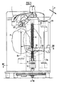
- the router T according to the invention which has a surface 1 of revolution, in this case cylindrical, capable of coming to bear on the surface of the product P to be peeled so as to limit the penetration, this surface having a very small diameter, for example of the order of 20 mm. Furthermore, the router has a very small number of protrusions 2, for example two for balancing in rotation.
- the router T with its bearing surface 1 can for example be made of molded plastic, while the projections 2 are advantageously constituted by the projecting part of a metal blade which can be sharpened or not.
- the protruding height of each projection beyond the surface 1 defines the maximum pass depth and can possibly be modified by having several types of router.
- this router rotates around its axis AT at a very high speed of rotation, for example 20,000 rpm, so that the tangential speed of the projections 2 is at least of the order of 20 m / s, or in any case greater than 8 m / s.
- This high speed of rotation requires only a relatively low torque, so that it can easily be ensured using a small motor 3 with direct drive placed at the other end of the shaft A d 'AT axis.
- any other type of transmission for example by belt, or drive, for example by turbine, would be usable.
- the assembly 4 comprising the bearings 5 and 6 of the shaft A, and possibly the motor 3 as in the present case, or the receiving member of the transmission, is mounted oscillating around an axis oscillation AM perpendicular to AT.
- This axis AM is for example carried by a cage C in the form of a yoke, visible in particular in FIGS. 3, 5 and 6, and mounted itself rotating around an axis AC which is perpendicular to the axis of motor articulation AM, and preferably eccentric, that is to say not concurrent with the previous one, as seen in particular in FIG. 6.
- a restoring torque exerted for example by a spring r, produces a rotation of the assembly 4 around this axis to produce at the level of the router T a low effort of application of the latter on the product P, of the order of 0.3 N or at most 0.5 N. Indeed, the high speed of rotation of the router does not require a strong pressure on the product.
- the product P itself, vegetable or fruit, can be driven in a helical movement to ensure systematic exploration of its surface by the router T, without either requiring a large torque for rotation or great force d drive in translation.
- this double entrainment of the product P is ensured by a short pin B, the end of which is pointed and cut into the shape of a screw with large pitch in the manner of a corkscrew, so as to be able to be screwed directly in a short length of the product corresponding to the smallest dimension in length of the products treated.
- the simple rotation of the spindle B on itself is sufficient to ensure the penetration of the spindle into the product P, for example momentarily immobilized by hand, then in a second step, the drive in rotation and in translation of this product.
- a carriage 10 On this screw V is mounted a carriage 10, visible in particular in FIGS. 2 and 4 and which constitutes a nut capable of moving in translation along the screw due to the rotation of the latter, in one direction and in the other.
- This puppy 10 assumes the shape of an arm whose end carries the bearings 11 and 12 of the base of the previous pin B.
- a suitable transmission makes it possible to transmit the rotational movement of the screw V to the spindle B.
- this transmission takes place using a pulley 13, wedged on the spindle B between the bearings 11 and 12, and of a belt 14 which passes directly between two threads of the screw V, which ensures both the friction drive of the belt and its longitudinal path under the same conditions as the carriage 10.
- any other mode of transmission would be usable.
- the transmission ratio can be one or different from one.
- the carriage 10 Due to the inevitable friction between the screw V and the carriage 10, as well as between the spindle B and its bearings 11 and 12, the torque of which is passed on to the screw by the belt 14, and also the inertia and the resistance when driving the product P which oppose the movement, when the screw V is driven in rotation, the carriage 10 quite naturally has a tendency to rotate with this screw rather than to move in translation thereon.
- the carriage 10 is therefore provided with a rear extension 15 capable of abutting and sliding vertically on a stop 16 secured to the frame of the apparatus when the screw turns anticlockwise. from above, and to come in the same way to abut and slide vertically against another abutment 17 secured to the frame when the screw rotates clockwise.
- an intermediate stop 18 which, as can be seen in FIG. 2, extends only over a small part of the height.
- the cage C is positioned at the start in such a way that the motor articulation axis AM is inclined substantially at 45 ° relative to the axis AB of the spindle B, and in one direction.
- the AM axis must rotate slowly around the cage axis AC until it exceeds the vertical and reaches a similar inclination and in the opposite direction.
- this second inclination can stop at about twenty degrees from the vertical.
- the router explores the entire surface of the product P by drawing parallel grooves whose apparent pitch is substantially equal to that indicated above, the direction of rotation of the router T, represented by the arrow S in FIGS. 1 and 5, being chosen in such a way that the router always attacks the skin of the product P from below, starting from the previous turn already peeled. This is particularly important for earthy products, such as potatoes or carrots, to avoid excessive wear of the projections 2 and to leave the peeled product P perfectly clean.
- This rotational movement of the cage C around the axis AC can be produced by any suitable means, continuous or discontinuous, but it can be obtained in a very simple manner in the example shown using a pulley 19 driving the cage C by friction and itself driven by a belt 20 from the screw V and by means of a torque wheel 21 and tangent screw 22, the latter being carried at the end of the screw V.
- the shaft 23 driven by the wheel 21 drives the belt 20 at its other end.
- a substantially cylindrical guide 27 is provided, visible in particular in FIGS. 1, 3, 5 and 6, and on the edge of which comes a stop finger 28 limiting the tilting stroke of the assembly 4 around the axis AM .
- this finger 28 enters the bottom of a notch 30 of the guide 27 and abuts against a retractable stop 31, which opposes the rotation of the cage C until the moment, the router T having encountered the product and having been lifted by it in the direction F, the finger 28 escapes from the stop 31 which defined the starting position and begins its slow rotation as a function of the indicated drive.
- the drive pulley integral with the shaft 23 can advantageously be replaced by a section of helical screw 32 as in the example shown, but any other mode of transmission would be naturally applicable.
- the angular position of the cage C at the end of peeling is defined by a simple angular stop operating at the level of the ramp 24 or of the guide 27.
- the device is advantageously completed by a centering shovel 33, visible in FIGS. 1 and 4 and articulated around an axis 34 secured to the frame of the device.
- This shovel has a concave part 35 serving to center the base of the product directly above the spindle B when the latter is in the middle position, defined by the stop of the rear extension 15 of the carriage 10 on the intermediate stop 18.
- the shovel 33 has a release notch 36 allowing the base of the spindle B to pass during the rotation of the carriage 10 from the middle position to the position 8 1 in FIG. 4.
- the spindle B is screwed in exactly its entire length, and at the same time the rear extension 15 of the carriage 10 has come to l 'upper end of the stop 18, without however escaping therefrom.
- the motor 7 is then stopped by this stop contact.
- the operator After removing his hand, the operator then actuates another manual control which can for example consist of an additional stroke of the shovel 33, and another contact restarts the motor 7, always in the same direction, in short -circuiting for example the previous stop contact.
- another manual control which can for example consist of an additional stroke of the shovel 33, and another contact restarts the motor 7, always in the same direction, in short -circuiting for example the previous stop contact.
- the product P begins its helical movement upwards.
- the router T rotates in the direction indicated, and the cage C, driven by friction by the pulley 19, nevertheless remains in the stationary position, blocked by the finger 28 which presses on the stop 31.
- the top of it comes to meet the router T, which produces the machining of a peeling spiral on its end cap, at the same time as the release of the finger 28 allowing the slow subsequent rotation of the cage C around its axis AC as described above.
- the router explores its surface by tracing turns which pass from an almost planar spiral to almost helical turns, to end at the other end again by a substantially planar spiral, all these turns having a relatively constant apparent pitch thanks to the progressive variation of the inclination of the AM axis as indicated above.
- the progressive retraction of the cage C allows the router T to avoid encountering the spindle B, the latter comprising, moreover, a non-threaded part at its base with a length substantially equal to the diameter of this router to avoid meeting it with the carriage.
- the return of the router to the vicinity of the axis AB takes place for the position of the carriage 10 corresponding to the top of its travel, a position independent of the length of the product P and which is determined by an upper limit switch not shown .
- the product P is therefore itself driven freely by this halicoidal movement until its base comes into contact with the bearing surface 37 of the evacuation station. This has the effect of immobilizing it by friction, thus allowing the unscrewing of the spindle B which, once freed from the product P, continues on its own its downward movement until the lower end of the stroke.
- the skin particles of the product P are projected tangentially towards a zone of reduced extent where their accumulation does not risk in any way hampering the progress of the 'apparatus.
- this zone is preferably formed in the form of a removable receptacle, not shown, allowing it to be cleaned.
- Classic protection devices not shown for the purpose of simplification, make it possible to protect the mechanism, especially the screw, against accidental splashes of dirt.
- the same type of router can be used practically for most products, whether it is hard-fleshed vegetables such as carrots, or tender-fleshed vegetables such as potatoes, or vegetables stringy flesh such as turnips or onions, and also thin-skinned fruits such as apples or pears. Since no adaptation or calibration of the products is necessary, it is therefore possible for the user to chain different products, for example carrots, potatoes, turnips, onions, etc. without having to change anything on the device. As regards thick-skinned fruits, in particular oranges and lemons, it is possible, as we have seen above, to use a special toupe, the protrusion of the projections 2 of which is greater.
- Another solution is to act on the relative speed of the router relative to the speed of the screw, which is particularly simple in the case of the example described where there are two independent motors 3 and 7.
- a last solution is to repeat the peeling cycle several times on the same citrus fruit. This latter solution also has the advantage that, on the first pass, it is possible, if desired, to recover the zest of the fruit in the receptacle indicated above, while at the following pass (s), the white skin is eliminated. .
Claims (11)
Priority Applications (1)
| Application Number | Priority Date | Filing Date | Title |
|---|---|---|---|
| AT86107938T ATE52672T1 (de) | 1985-06-26 | 1986-06-11 | Schaelmaschine fuer obst und gemuese. |
Applications Claiming Priority (2)
| Application Number | Priority Date | Filing Date | Title |
|---|---|---|---|
| FR8509737A FR2583969B1 (fr) | 1985-06-26 | 1985-06-26 | Eplucheuse de fruits et legumes |
| FR8509737 | 1985-06-26 |
Publications (2)
| Publication Number | Publication Date |
|---|---|
| EP0207334A1 EP0207334A1 (de) | 1987-01-07 |
| EP0207334B1 true EP0207334B1 (de) | 1990-05-16 |
Family
ID=9320697
Family Applications (1)
| Application Number | Title | Priority Date | Filing Date |
|---|---|---|---|
| EP86107938A Expired - Lifetime EP0207334B1 (de) | 1985-06-26 | 1986-06-11 | Schälmaschine für Obst und Gemüse |
Country Status (7)
| Country | Link |
|---|---|
| US (1) | US4765234A (de) |
| EP (1) | EP0207334B1 (de) |
| JP (1) | JPS623777A (de) |
| AT (1) | ATE52672T1 (de) |
| DE (1) | DE3671155D1 (de) |
| ES (1) | ES8707659A1 (de) |
| FR (1) | FR2583969B1 (de) |
Families Citing this family (32)
| Publication number | Priority date | Publication date | Assignee | Title |
|---|---|---|---|---|
| US4704959A (en) * | 1986-01-22 | 1987-11-10 | Scallen David J | Apparatus for cutting potatoes and onions |
| ES2012107A6 (es) * | 1988-07-07 | 1990-03-01 | Perez Gonzalvo Jose | Pelafrutas. |
| US4937088A (en) * | 1988-12-29 | 1990-06-26 | The Procter & Gamble Company | Method of and apparatus for extracting juice and meat from a fruit |
| IL97613A (en) * | 1990-03-22 | 1994-06-24 | Ser Gonzalez Clemente Del | Fruit peeling machine |
| US5089286A (en) * | 1990-07-18 | 1992-02-18 | National Presto Industries, Inc. | Appliance for spirally slicing fruits and vegetables |
| US5138940A (en) * | 1990-07-18 | 1992-08-18 | National Presto Industries, Inc. | Appliance for spirally slicing fruits and vegetables |
| IT1262794B (it) * | 1993-06-09 | 1996-07-04 | Tiziana Tomelleri | Macchina per la sbucciatura automatica di frutti oblunghi, vantaggiosamente di kiwi |
| US5558011A (en) * | 1995-09-05 | 1996-09-24 | Heim; Stephen J. | Fruit paring and cutting apparatus |
| NL1004058C2 (nl) * | 1996-09-18 | 1998-03-19 | Schaap Beheer B V B | Werkwijze en inrichting voor het mechanisch schillen van aardappelen. |
| US5690022A (en) * | 1996-12-11 | 1997-11-25 | Chai; Liao-Chu | Peeling device |
| US6053098A (en) * | 1999-09-17 | 2000-04-25 | Benriner Co., Ltd. | Rotary root vegetable slicer |
| US6523464B1 (en) | 2001-09-19 | 2003-02-25 | Ronald J. Widelo | Automated peeler |
| US6659522B2 (en) * | 2002-04-04 | 2003-12-09 | Hallie Anne Byth | Fruit and vegetable holding utensil |
| WO2004113033A1 (en) * | 2003-06-20 | 2004-12-29 | Hermanus Willem Van Heerden | A device for cutting a fruit or vegetable in a helical shape |
| JP3878593B2 (ja) * | 2003-10-20 | 2007-02-07 | 株式会社ムロコーポレーション | 果菜の皮むき器 |
| US7913600B2 (en) * | 2005-07-22 | 2011-03-29 | Odom Jr Donald | Tourne cutting method and device |
| US7278346B2 (en) * | 2005-07-22 | 2007-10-09 | Odom Jr Donald | Tourne cutting method, device and kit |
| US9375858B2 (en) * | 2008-08-06 | 2016-06-28 | Edible Arrangements, Llc | Method and device for removing rinds from a food item |
| NL2004648C2 (nl) * | 2010-05-03 | 2011-11-07 | Zti Mechatronics B V | Inrichting en werkwijze voor het schillen van gewassen. |
| WO2012118920A2 (en) * | 2011-03-01 | 2012-09-07 | Zip Zester Llc | Device for extracting zest from a fruit, and related extraction methods |
| US9433224B2 (en) * | 2013-06-28 | 2016-09-06 | Hua Long | Poultry processing equipment |
| CN103494501A (zh) * | 2013-09-10 | 2014-01-08 | 常熟市微尘电器有限公司 | 自动削水果机 |
| US11064913B2 (en) | 2013-10-25 | 2021-07-20 | Force Impact Technologies, Inc. | Impact sensing wearable device and method |
| US10820735B2 (en) | 2015-03-05 | 2020-11-03 | Whirlpool Corporation | Modular food processing and preparation device |
| USD815888S1 (en) | 2015-11-20 | 2018-04-24 | Andrea Vianello | Food cutter |
| USD901970S1 (en) | 2015-12-30 | 2020-11-17 | Whirlpool Corporation | Food processing device |
| CN107280440A (zh) * | 2016-04-04 | 2017-10-24 | 白先术 | 菠萝瓜果去皮机 |
| US10045650B2 (en) | 2016-12-31 | 2018-08-14 | Frederic William Brady, JR. | DC rechargeable battery powered appliance purposed to remove a thin outer layer of skin from vegetables and fruits |
| EP3542647A1 (de) * | 2018-03-22 | 2019-09-25 | Lurch AG | Fruchtschälvorrichtung |
| AU2019401356B2 (en) | 2018-12-20 | 2021-12-02 | Force Impact Technologies, Inc. | Mouth guard having user-notification feature of impact force and method of making the same |
| USD907448S1 (en) * | 2019-07-17 | 2021-01-12 | Progressive International Corporation | Apple paring machine frame |
| FR3136147A1 (fr) * | 2022-06-03 | 2023-12-08 | Seb S.A. | Dispositif et appareil de préparation culinaire pour pratiquer une découpe hélicoïdale sur un fruit ou un légume |
Family Cites Families (9)
| Publication number | Priority date | Publication date | Assignee | Title |
|---|---|---|---|---|
| US1872731A (en) * | 1926-06-28 | 1932-08-23 | California Packing Corp | Fruit peeling machine |
| US3013595A (en) * | 1958-12-08 | 1961-12-19 | Fmc Corp | Apparatus for processing fruit |
| US3113603A (en) * | 1961-09-11 | 1963-12-10 | Fmc Corp | Rotary cutter for peeling fruit |
| FR1481314A (fr) * | 1966-05-16 | 1967-05-19 | Atlas Pacifik Eng Co | Mécanisme perfectionné de coupe utilisable pour peler des poires et autres fruits |
| GB1224205A (en) * | 1967-04-10 | 1971-03-03 | Atlas Pacifik Eng Co | Apparatus for peeling double indented fruit |
| US3680614A (en) * | 1971-02-09 | 1972-08-01 | Ralph Polk Jr | Fruit peeling knife assembly |
| US3881406A (en) * | 1973-11-28 | 1975-05-06 | Artemio R Perez | Apparatus for peeling fruit or vegetables |
| IT1024276B (it) * | 1974-10-16 | 1978-06-20 | Tomelleri Giordano | Meccanismo di taglio a tornitura rotante per la sagomatura dei fondi di cuordi di carciofo |
| GB2037147A (en) * | 1978-12-11 | 1980-07-09 | Chen Shih Lin | Peeling-apparatus |
-
1985
- 1985-06-26 FR FR8509737A patent/FR2583969B1/fr not_active Expired
-
1986
- 1986-06-11 DE DE8686107938T patent/DE3671155D1/de not_active Expired - Lifetime
- 1986-06-11 EP EP86107938A patent/EP0207334B1/de not_active Expired - Lifetime
- 1986-06-11 AT AT86107938T patent/ATE52672T1/de not_active IP Right Cessation
- 1986-06-24 US US06/877,769 patent/US4765234A/en not_active Expired - Fee Related
- 1986-06-25 ES ES556737A patent/ES8707659A1/es not_active Expired
- 1986-06-26 JP JP61150628A patent/JPS623777A/ja active Pending
Also Published As
| Publication number | Publication date |
|---|---|
| ES8707659A1 (es) | 1987-08-16 |
| DE3671155D1 (de) | 1990-06-21 |
| EP0207334A1 (de) | 1987-01-07 |
| ES556737A0 (es) | 1987-08-16 |
| US4765234A (en) | 1988-08-23 |
| FR2583969A1 (fr) | 1987-01-02 |
| FR2583969B1 (fr) | 1987-09-11 |
| ATE52672T1 (de) | 1990-06-15 |
| JPS623777A (ja) | 1987-01-09 |
Similar Documents
| Publication | Publication Date | Title |
|---|---|---|
| EP0207334B1 (de) | Schälmaschine für Obst und Gemüse | |
| EP0346392B1 (de) | Vorrichtung zur gewinnung von saft und pulpe aus früchten und gemüsen | |
| CA2404512C (fr) | Dispositif d'entrainement d'un outil rotatif pour appareil de traitement alimentaire, et appareil de traitement alimentaire pourvu d'un tel dispositif | |
| EP0078232B1 (de) | Aufspiessvorrichtung zum Herstellen von Fleischspiessen und/oder anderer Nahrungsmittel | |
| EP0319556B1 (de) | Schälmaschine für obst und gemüse | |
| FR2503545A1 (fr) | Procede et appareil de pelage de fruits, notamment de tomates | |
| EP0081466B1 (de) | Raspelmaschine für Käse | |
| FR2521836A1 (fr) | Machine a tourner les legumes ou produits analogues | |
| EP1759600B1 (de) | Verfahren und Vorrichtung zum Abblättern der äusseren Blätter von Salaten | |
| FR2692188A1 (fr) | Dispositif portatif de pelage et de découpe en tranches de produits avec suppression éventuelle du trognon. | |
| FR2625379A1 (fr) | Dispositif et procede pour la coupe selective du gainage multicouche d'un cable optique ou electrique | |
| EP0114766B1 (de) | Haushaltsgerät zur Zubereitung von Nahrungsmitteln | |
| EP0086499B1 (de) | Gerät zum Verzieren von Konditoreiprodukten und Backwaren | |
| FR2707844A1 (fr) | Machine pour découper les fonds d'artichauts. | |
| FR2892289A1 (fr) | Appareil de traitement d'aliments | |
| BE502572A (de) | ||
| FR2508283A1 (fr) | Procede et appareil pour elaborer des produits legumiers sous forme spherique | |
| CH637040A5 (en) | Method and device for cleaning cheese rounds | |
| FR2469882A1 (fr) | Appareil pour l'obtention de fonds d'artichauts | |
| WO1993005934A1 (fr) | Dispositif d'eminçage de champignons | |
| FR2647387A1 (fr) | Procede et appareil de coupe de forme dans les legumes et les fruits | |
| FR3139440A1 (fr) | Manchon pour tête d’étrognage, et tête d’étrognage correspondante | |
| BE399394A (de) | ||
| EP0060308B1 (de) | Vorrichtung zum Verarbeiten von Mollusken, insbesondere Tintenfisch | |
| FR2667484A1 (fr) | Procede et machine pour eteter et equeuter des plantes a bulbe allonge, et notamment des echalotes. |
Legal Events
| Date | Code | Title | Description |
|---|---|---|---|
| PUAI | Public reference made under article 153(3) epc to a published international application that has entered the european phase |
Free format text: ORIGINAL CODE: 0009012 |
|
| AK | Designated contracting states |
Kind code of ref document: A1 Designated state(s): AT BE CH DE FR GB IT LI LU NL SE |
|
| 17P | Request for examination filed |
Effective date: 19870703 |
|
| 17Q | First examination report despatched |
Effective date: 19880823 |
|
| GRAA | (expected) grant |
Free format text: ORIGINAL CODE: 0009210 |
|
| AK | Designated contracting states |
Kind code of ref document: B1 Designated state(s): AT BE CH DE FR GB IT LI LU NL SE |
|
| PG25 | Lapsed in a contracting state [announced via postgrant information from national office to epo] |
Ref country code: AT Effective date: 19900516 Ref country code: SE Effective date: 19900516 Ref country code: NL Effective date: 19900516 |
|
| REF | Corresponds to: |
Ref document number: 52672 Country of ref document: AT Date of ref document: 19900615 Kind code of ref document: T |
|
| ITF | It: translation for a ep patent filed |
Owner name: BARZANO' E ZANARDO MILANO S.P.A. |
|
| REF | Corresponds to: |
Ref document number: 3671155 Country of ref document: DE Date of ref document: 19900621 |
|
| PG25 | Lapsed in a contracting state [announced via postgrant information from national office to epo] |
Ref country code: CH Effective date: 19900630 Ref country code: BE Effective date: 19900630 Ref country code: LU Free format text: LAPSE BECAUSE OF NON-PAYMENT OF DUE FEES Effective date: 19900630 Ref country code: LI Effective date: 19900630 |
|
| PG25 | Lapsed in a contracting state [announced via postgrant information from national office to epo] |
Ref country code: GB Effective date: 19900716 |
|
| GBT | Gb: translation of ep patent filed (gb section 77(6)(a)/1977) | ||
| NLV1 | Nl: lapsed or annulled due to failure to fulfill the requirements of art. 29p and 29m of the patents act | ||
| BERE | Be: lapsed |
Owner name: CAILLIOT SERGE Effective date: 19900630 |
|
| REG | Reference to a national code |
Ref country code: CH Ref legal event code: PL |
|
| PG25 | Lapsed in a contracting state [announced via postgrant information from national office to epo] |
Ref country code: DE Effective date: 19910301 |
|
| GBPC | Gb: european patent ceased through non-payment of renewal fee | ||
| PLBE | No opposition filed within time limit |
Free format text: ORIGINAL CODE: 0009261 |
|
| STAA | Information on the status of an ep patent application or granted ep patent |
Free format text: STATUS: NO OPPOSITION FILED WITHIN TIME LIMIT |
|
| PG25 | Lapsed in a contracting state [announced via postgrant information from national office to epo] |
Ref country code: FR Effective date: 19910430 |
|
| 26N | No opposition filed | ||
| REG | Reference to a national code |
Ref country code: FR Ref legal event code: ST |
|
| PG25 | Lapsed in a contracting state [announced via postgrant information from national office to epo] |
Ref country code: IT Free format text: LAPSE BECAUSE OF NON-PAYMENT OF DUE FEES;WARNING: LAPSES OF ITALIAN PATENTS WITH EFFECTIVE DATE BEFORE 2007 MAY HAVE OCCURRED AT ANY TIME BEFORE 2007. THE CORRECT EFFECTIVE DATE MAY BE DIFFERENT FROM THE ONE RECORDED. Effective date: 20050611 |
|
| PG25 | Lapsed in a contracting state [announced via postgrant information from national office to epo] |
Ref country code: FR Effective date: 19900630 |