EP0207334B1 - Peeler for fruits and vegetables - Google Patents
Peeler for fruits and vegetables Download PDFInfo
- Publication number
- EP0207334B1 EP0207334B1 EP86107938A EP86107938A EP0207334B1 EP 0207334 B1 EP0207334 B1 EP 0207334B1 EP 86107938 A EP86107938 A EP 86107938A EP 86107938 A EP86107938 A EP 86107938A EP 0207334 B1 EP0207334 B1 EP 0207334B1
- Authority
- EP
- European Patent Office
- Prior art keywords
- product
- axis
- movement
- cutter
- spindle
- Prior art date
- Legal status (The legal status is an assumption and is not a legal conclusion. Google has not performed a legal analysis and makes no representation as to the accuracy of the status listed.)
- Expired - Lifetime
Links
Images


Classifications
-
- A—HUMAN NECESSITIES
- A47—FURNITURE; DOMESTIC ARTICLES OR APPLIANCES; COFFEE MILLS; SPICE MILLS; SUCTION CLEANERS IN GENERAL
- A47J—KITCHEN EQUIPMENT; COFFEE MILLS; SPICE MILLS; APPARATUS FOR MAKING BEVERAGES
- A47J17/00—Household peeling, stringing, or paring implements or machines
- A47J17/14—Machines for peeling
- A47J17/16—Peeling machines with rotary fruit-holding spindles and fixed or movable peeler blades
-
- A—HUMAN NECESSITIES
- A23—FOODS OR FOODSTUFFS; TREATMENT THEREOF, NOT COVERED BY OTHER CLASSES
- A23N—MACHINES OR APPARATUS FOR TREATING HARVESTED FRUIT, VEGETABLES OR FLOWER BULBS IN BULK, NOT OTHERWISE PROVIDED FOR; PEELING VEGETABLES OR FRUIT IN BULK; APPARATUS FOR PREPARING ANIMAL FEEDING- STUFFS
- A23N7/00—Peeling vegetables or fruit
- A23N7/02—Peeling potatoes, apples or similarly shaped vegetables or fruit
- A23N7/023—Peeling potatoes, apples or similarly shaped vegetables or fruit one by one
- A23N7/026—Peeling machines therefor with rotary fruit holding spindles and fixed or movable peeler blades
Definitions
- the invention relates to apparatus for peeling or peeling various products, such as fruit or vegetables, that is to say removing the skin, husk or bark which is referred to below as skin.
- the above devices are not suitable because on the one hand, of the rapid wear of the cutting edges, in particular with products with earthy skin, and on the other hand, irregular shapes of the vegetables such than potatoes, and differences in the hardness of their flesh, such as the difference between a carrot and a potato. For this reason, it is preferable to use grindstones or abrasive devices which treat vegetables in bulk under a stream of water, but with very significant losses in peeling weight, or even for quite specific cases such as than potatoes, grazing knives which are very fragile and again have the disadvantage of stuffing the peel.
- the object of the invention is to eliminate the above drawbacks by making a device which is suitable for both and without particular adaptation to all the most common types of fruit and vegetables, which eliminates the problem of stuffing and evacuation. peels, and which also eliminates the problem of wear of the cutting edges as well as the difficulties due to irregularities in shape.
- the invention is based on the use, in a peeler according to the preamble of claim 1, of a tool of the router type comprising:
- said drive means of the router being able to drive the latter in rotation about its axis at high speed so that the tangential speed of the projections is greater than 8 m / s, and preferably close to 20 m / s so as to constantly project loose particles of skin away, as the router explores the surface of the product in parallel turns,
- said drive means being capable of driving the router in a direction of rotation relative to the exploration movement such that the projections attack the skin of the product from below starting from the neighboring turn already peeled.
- this router in particular its high speed of rotation, also have the advantage of bringing into play only very weak and regular forces, allowing in particular
- the product can be driven in rotation and in translation using a simple spindle in the shape of a corkscrew, allowing direct screwing and unscrewing in the product using only a fraction of the stroke of these same movements. of translation and rotation.
- the axis of the router is mounted in bearings so as to oscillate about a perpendicular axis of articulation, this axis of articulation being in turn mounted in the bearings of a cage in the form of a yoke capable of rotating around a perpendicular axis, or even orthogonal and eccentric with respect to the previous one, so that
- the oscillation axis makes an angle close to 45 ° with the spindle carrying the product in a direction such that meeting the router with the product automatically causes the oblique leakage of the router, and that
- this articulation axis makes with this same spindle an angle of opposite direction, and preferably close to 20 °.
- This arrangement is intended to ensure automatic operation and a substantially constant apparent pitch between the turns.
- the router T according to the invention which has a surface 1 of revolution, in this case cylindrical, capable of coming to bear on the surface of the product P to be peeled so as to limit the penetration, this surface having a very small diameter, for example of the order of 20 mm. Furthermore, the router has a very small number of protrusions 2, for example two for balancing in rotation.
- the router T with its bearing surface 1 can for example be made of molded plastic, while the projections 2 are advantageously constituted by the projecting part of a metal blade which can be sharpened or not.
- the protruding height of each projection beyond the surface 1 defines the maximum pass depth and can possibly be modified by having several types of router.
- this router rotates around its axis AT at a very high speed of rotation, for example 20,000 rpm, so that the tangential speed of the projections 2 is at least of the order of 20 m / s, or in any case greater than 8 m / s.
- This high speed of rotation requires only a relatively low torque, so that it can easily be ensured using a small motor 3 with direct drive placed at the other end of the shaft A d 'AT axis.
- any other type of transmission for example by belt, or drive, for example by turbine, would be usable.
- the assembly 4 comprising the bearings 5 and 6 of the shaft A, and possibly the motor 3 as in the present case, or the receiving member of the transmission, is mounted oscillating around an axis oscillation AM perpendicular to AT.
- This axis AM is for example carried by a cage C in the form of a yoke, visible in particular in FIGS. 3, 5 and 6, and mounted itself rotating around an axis AC which is perpendicular to the axis of motor articulation AM, and preferably eccentric, that is to say not concurrent with the previous one, as seen in particular in FIG. 6.
- a restoring torque exerted for example by a spring r, produces a rotation of the assembly 4 around this axis to produce at the level of the router T a low effort of application of the latter on the product P, of the order of 0.3 N or at most 0.5 N. Indeed, the high speed of rotation of the router does not require a strong pressure on the product.
- the product P itself, vegetable or fruit, can be driven in a helical movement to ensure systematic exploration of its surface by the router T, without either requiring a large torque for rotation or great force d drive in translation.
- this double entrainment of the product P is ensured by a short pin B, the end of which is pointed and cut into the shape of a screw with large pitch in the manner of a corkscrew, so as to be able to be screwed directly in a short length of the product corresponding to the smallest dimension in length of the products treated.
- the simple rotation of the spindle B on itself is sufficient to ensure the penetration of the spindle into the product P, for example momentarily immobilized by hand, then in a second step, the drive in rotation and in translation of this product.
- a carriage 10 On this screw V is mounted a carriage 10, visible in particular in FIGS. 2 and 4 and which constitutes a nut capable of moving in translation along the screw due to the rotation of the latter, in one direction and in the other.
- This puppy 10 assumes the shape of an arm whose end carries the bearings 11 and 12 of the base of the previous pin B.
- a suitable transmission makes it possible to transmit the rotational movement of the screw V to the spindle B.
- this transmission takes place using a pulley 13, wedged on the spindle B between the bearings 11 and 12, and of a belt 14 which passes directly between two threads of the screw V, which ensures both the friction drive of the belt and its longitudinal path under the same conditions as the carriage 10.
- any other mode of transmission would be usable.
- the transmission ratio can be one or different from one.
- the carriage 10 Due to the inevitable friction between the screw V and the carriage 10, as well as between the spindle B and its bearings 11 and 12, the torque of which is passed on to the screw by the belt 14, and also the inertia and the resistance when driving the product P which oppose the movement, when the screw V is driven in rotation, the carriage 10 quite naturally has a tendency to rotate with this screw rather than to move in translation thereon.
- the carriage 10 is therefore provided with a rear extension 15 capable of abutting and sliding vertically on a stop 16 secured to the frame of the apparatus when the screw turns anticlockwise. from above, and to come in the same way to abut and slide vertically against another abutment 17 secured to the frame when the screw rotates clockwise.
- an intermediate stop 18 which, as can be seen in FIG. 2, extends only over a small part of the height.
- the cage C is positioned at the start in such a way that the motor articulation axis AM is inclined substantially at 45 ° relative to the axis AB of the spindle B, and in one direction.
- the AM axis must rotate slowly around the cage axis AC until it exceeds the vertical and reaches a similar inclination and in the opposite direction.
- this second inclination can stop at about twenty degrees from the vertical.
- the router explores the entire surface of the product P by drawing parallel grooves whose apparent pitch is substantially equal to that indicated above, the direction of rotation of the router T, represented by the arrow S in FIGS. 1 and 5, being chosen in such a way that the router always attacks the skin of the product P from below, starting from the previous turn already peeled. This is particularly important for earthy products, such as potatoes or carrots, to avoid excessive wear of the projections 2 and to leave the peeled product P perfectly clean.
- This rotational movement of the cage C around the axis AC can be produced by any suitable means, continuous or discontinuous, but it can be obtained in a very simple manner in the example shown using a pulley 19 driving the cage C by friction and itself driven by a belt 20 from the screw V and by means of a torque wheel 21 and tangent screw 22, the latter being carried at the end of the screw V.
- the shaft 23 driven by the wheel 21 drives the belt 20 at its other end.
- a substantially cylindrical guide 27 is provided, visible in particular in FIGS. 1, 3, 5 and 6, and on the edge of which comes a stop finger 28 limiting the tilting stroke of the assembly 4 around the axis AM .
- this finger 28 enters the bottom of a notch 30 of the guide 27 and abuts against a retractable stop 31, which opposes the rotation of the cage C until the moment, the router T having encountered the product and having been lifted by it in the direction F, the finger 28 escapes from the stop 31 which defined the starting position and begins its slow rotation as a function of the indicated drive.
- the drive pulley integral with the shaft 23 can advantageously be replaced by a section of helical screw 32 as in the example shown, but any other mode of transmission would be naturally applicable.
- the angular position of the cage C at the end of peeling is defined by a simple angular stop operating at the level of the ramp 24 or of the guide 27.
- the device is advantageously completed by a centering shovel 33, visible in FIGS. 1 and 4 and articulated around an axis 34 secured to the frame of the device.
- This shovel has a concave part 35 serving to center the base of the product directly above the spindle B when the latter is in the middle position, defined by the stop of the rear extension 15 of the carriage 10 on the intermediate stop 18.
- the shovel 33 has a release notch 36 allowing the base of the spindle B to pass during the rotation of the carriage 10 from the middle position to the position 8 1 in FIG. 4.
- the spindle B is screwed in exactly its entire length, and at the same time the rear extension 15 of the carriage 10 has come to l 'upper end of the stop 18, without however escaping therefrom.
- the motor 7 is then stopped by this stop contact.
- the operator After removing his hand, the operator then actuates another manual control which can for example consist of an additional stroke of the shovel 33, and another contact restarts the motor 7, always in the same direction, in short -circuiting for example the previous stop contact.
- another manual control which can for example consist of an additional stroke of the shovel 33, and another contact restarts the motor 7, always in the same direction, in short -circuiting for example the previous stop contact.
- the product P begins its helical movement upwards.
- the router T rotates in the direction indicated, and the cage C, driven by friction by the pulley 19, nevertheless remains in the stationary position, blocked by the finger 28 which presses on the stop 31.
- the top of it comes to meet the router T, which produces the machining of a peeling spiral on its end cap, at the same time as the release of the finger 28 allowing the slow subsequent rotation of the cage C around its axis AC as described above.
- the router explores its surface by tracing turns which pass from an almost planar spiral to almost helical turns, to end at the other end again by a substantially planar spiral, all these turns having a relatively constant apparent pitch thanks to the progressive variation of the inclination of the AM axis as indicated above.
- the progressive retraction of the cage C allows the router T to avoid encountering the spindle B, the latter comprising, moreover, a non-threaded part at its base with a length substantially equal to the diameter of this router to avoid meeting it with the carriage.
- the return of the router to the vicinity of the axis AB takes place for the position of the carriage 10 corresponding to the top of its travel, a position independent of the length of the product P and which is determined by an upper limit switch not shown .
- the product P is therefore itself driven freely by this halicoidal movement until its base comes into contact with the bearing surface 37 of the evacuation station. This has the effect of immobilizing it by friction, thus allowing the unscrewing of the spindle B which, once freed from the product P, continues on its own its downward movement until the lower end of the stroke.
- the skin particles of the product P are projected tangentially towards a zone of reduced extent where their accumulation does not risk in any way hampering the progress of the 'apparatus.
- this zone is preferably formed in the form of a removable receptacle, not shown, allowing it to be cleaned.
- Classic protection devices not shown for the purpose of simplification, make it possible to protect the mechanism, especially the screw, against accidental splashes of dirt.
- the same type of router can be used practically for most products, whether it is hard-fleshed vegetables such as carrots, or tender-fleshed vegetables such as potatoes, or vegetables stringy flesh such as turnips or onions, and also thin-skinned fruits such as apples or pears. Since no adaptation or calibration of the products is necessary, it is therefore possible for the user to chain different products, for example carrots, potatoes, turnips, onions, etc. without having to change anything on the device. As regards thick-skinned fruits, in particular oranges and lemons, it is possible, as we have seen above, to use a special toupe, the protrusion of the projections 2 of which is greater.
- Another solution is to act on the relative speed of the router relative to the speed of the screw, which is particularly simple in the case of the example described where there are two independent motors 3 and 7.
- a last solution is to repeat the peeling cycle several times on the same citrus fruit. This latter solution also has the advantage that, on the first pass, it is possible, if desired, to recover the zest of the fruit in the receptacle indicated above, while at the following pass (s), the white skin is eliminated. .
Abstract
Description
L'invention concerne les appareils destinés à peler ou éplucher des produits divers, tels que fruits ou légumes, c'est-à-dire à en retirer la peau, enveloppe ou écorce qui désignée ci-aprés par peau.The invention relates to apparatus for peeling or peeling various products, such as fruit or vegetables, that is to say removing the skin, husk or bark which is referred to below as skin.
Pour l'épluchage des fruits, il est connu d'utiliser le principe du tour, avec un ou plusieurs outils fixes ou rotatifs qui possèdent au moins une partie tranchante et qui tentent d'imiter l'épluchage manuel, c'est-à-dire de détacher une pelure continue, comme c'est le cas par exemple des dispositifs décrits dans les documents FR-A-1 585 006, US-A-3 680 614, et FR-A-1 481 314. Pour un appareil automatique, la présence d'une telle pelure continue est un grave inconvénient par suite de sa tendance à bourrer et à gêner l'action de l'outil. Pour y remédier, il est connu, d'après le document US-A-3 113603 d'utiliser un couteau rotatif à tranchant cylindrique combiné avec un disque qui soutient le tranchant cylindrique et qui est muni de fenêtres affûtées dans le plan du disque, de manière à recouper transversalement le ruban de pelure en tronçons plus réduits facilitant son évacuation. Il est connu également, d'après le document FR-A-1 248 668, décrivant un appareil conforme au préambule de la revendication 1, d'utiliser un couteau rotatif en forme de fraise très platé comportant un grand nombre de dents tranchantes réparties sur un diamètre important afin de réaliser de petits copeaux dont l'évacuation est laissée au hasard.For the peeling of fruits, it is known to use the principle of the lathe, with one or more fixed or rotary tools which have at least a sharp part and which try to imitate the manual peeling, that is to say say to detach a continuous peel, as is the case for example of the devices described in documents FR-A-1 585 006, US-A-3 680 614, and FR-A-1 481 314. For an automatic device , the presence of such a continuous peel is a serious drawback owing to its tendency to stuff and hinder the action of the tool. To remedy this, it is known from document US-A-3 113603 to use a rotary knife with a cylindrical cutting edge combined with a disc which supports the cylindrical cutting edge and which is provided with sharpened windows in the plane of the disc, so as to cross transversely the strip of skin in smaller sections facilitating its evacuation. It is also known, from document FR-A-1 248 668, describing an apparatus in accordance with the preamble of claim 1, to use a rotary knife in the shape of a very flat strawberry comprising a large number of sharp teeth distributed over a large diameter in order to make small chips whose evacuation is left to chance.
Pour l'épluchage des légumes, les dispositifs précédents ne conviennent pas en raison d'une- part, de l'usure rapide des arêtes tranchantes, notamment avec des produits à peau terreuse, et d'autre part, des formes irrégulières des légumes tels que les pommes de terre, et des différences de dureté de leur chair, telle que la différence qui existe entre un carotte et une pomme de terre. Pour cette raison, on utilise de préférence les meules ou les dispositifs abrasifs qui traitent les légumes en vrac sous courant d'eau, mais avec des pertes de poids à l'épluchage- très importantes, ou encore pour des cas tout à fait particuliers tels que les pommes de terre, des couteaux rasants qui sont très fragiles et présentent à nouveau l'inconvénient du bourrage de la pelure.For the peeling of vegetables, the above devices are not suitable because on the one hand, of the rapid wear of the cutting edges, in particular with products with earthy skin, and on the other hand, irregular shapes of the vegetables such than potatoes, and differences in the hardness of their flesh, such as the difference between a carrot and a potato. For this reason, it is preferable to use grindstones or abrasive devices which treat vegetables in bulk under a stream of water, but with very significant losses in peeling weight, or even for quite specific cases such as than potatoes, grazing knives which are very fragile and again have the disadvantage of stuffing the peel.
Le but de l'invention est d'éliminer les inconvénients précédents en réalisant un dispositif qui convienne à la fois et sans adaptation particulière à tous les types les plus courants de fruits et de légumes, qui élimine le problème du bourrage et de l'évacuation des pelures, et qui élimine également le problème d'usure des tranchants ainsi que les difficultés dues aux irrégularités de forme.The object of the invention is to eliminate the above drawbacks by making a device which is suitable for both and without particular adaptation to all the most common types of fruit and vegetables, which eliminates the problem of stuffing and evacuation. peels, and which also eliminates the problem of wear of the cutting edges as well as the difficulties due to irregularities in shape.
L'invention est basée sur l'utilisation, dans une éplucheuse conforme au préambule de la revendication 1, d'un outil du type toupie comportant:The invention is based on the use, in a peeler according to the preamble of claim 1, of a tool of the router type comprising:
une partie de révolution de petit diamètre, apte à venir pénétrer même dans les parties concaves des formes irrégulières du produit et susceptible de venir au contact de celui cia part of revolution of small diameter, able to penetrate even into the concave parts of the irregular shapes of the product and capable of coming into contact with it
une ou plusieurs dents tranchantes ou non, formant des saillies d'un depassement déterminé au-delà de cette partie de révolution, le nombre de dents étant de préférence égal à deuxone or more teeth, cutting or not, forming protrusions of a determined protrusion beyond this part of revolution, the number of teeth preferably being equal to two
ledit moyen d'entraînement de la toupie étant apte à entrainer celle-ci en rotation autour de son axe à grande vitesse de telle manière que la vitesse tangentielle des saillies soit supérieure à 8 m/s, et de préférence voisine de 20 m/s, de manière à projeter constamment au loin les particules de peau détachées, au fur et à mesure que la toupie explore la surface du produit selon des spires parallèles,said drive means of the router being able to drive the latter in rotation about its axis at high speed so that the tangential speed of the projections is greater than 8 m / s, and preferably close to 20 m / s so as to constantly project loose particles of skin away, as the router explores the surface of the product in parallel turns,
ledit moyen d'entraînement étant apte à entraîner la toupie dansun sens de rotation relativement au mouvement d'exploration tel que les saillies attaquent la peau du produit par-dessous en partant de la spire voisine déjà pelée.said drive means being capable of driving the router in a direction of rotation relative to the exploration movement such that the projections attack the skin of the product from below starting from the neighboring turn already peeled.
Les caractéristiques de cette toupie, notamment sa vitesse de rotation élevée, présentent en outre l'intérêt de ne mettre en jeu que des forces très faibles et régulières, autorisant en particulierThe characteristics of this router, in particular its high speed of rotation, also have the advantage of bringing into play only very weak and regular forces, allowing in particular
de ne nécessiter qu'un très faible couple d'entraînement de la toupie, par moteur indépendant à entraînement direct ou par transmission,to require only a very low drive torque of the router, by independent motor with direct drive or by transmission,
de monter cette toupie d'une mainière sensitive, de manière que sa surface de révolution s'appuie sur la surface du produit, mais avec un très faible effort, ou couple de rappel lorsque l'ensemble est monté basculant,to mount this router in a sensitive manner, so that its surface of revolution rests on the surface of the product, but with very little effort, or return torque when the assembly is mounted tilting,
enfin, de ne nécessiter qu'un faible couple d'entraînement en rotation du produit et qu'une faible force de chariotage pour le dispositif destiné à produire le mouvement relatif d'exploration systématique à spires parallèles. En particulier, le produit peut être entraîné en rotation et en translation à l'aide d'une simple broche en forme de tire-bouchon, permettant un vissage et un dévissage directs dans le produit en utilisant seulement une fraction de course de ces mêmes mouvements de translation et de rotation.finally, to require only a low torque for rotating the product and only a low turning force for the device intended to produce the relative movement of systematic exploration with parallel turns. In particular, the product can be driven in rotation and in translation using a simple spindle in the shape of a corkscrew, allowing direct screwing and unscrewing in the product using only a fraction of the stroke of these same movements. of translation and rotation.
Selon une particularité importante de l'invention, l'axe de la toupie est monté dans des paliers de manière à osciller autour d'un axe d'articulation perpendiculaire, cet axe d'articulation étant à son tour monté dans les paliers d'une cage en forme de chape susceptible de tourner autour d'un axe perpendiculaire, ou encore orthogonal et excentré par rapport au précédent, de manière queAccording to an important feature of the invention, the axis of the router is mounted in bearings so as to oscillate about a perpendicular axis of articulation, this axis of articulation being in turn mounted in the bearings of a cage in the form of a yoke capable of rotating around a perpendicular axis, or even orthogonal and eccentric with respect to the previous one, so that
en début d'opération, l'axe d'oscillation fasse un angle voisin de 45° avec la broche portant le produit dans un sens tel que la recontre de la toupie avec le produit provoque automatiquement la fuite oblique de la toupie, et queat the start of the operation, the oscillation axis makes an angle close to 45 ° with the spindle carrying the product in a direction such that meeting the router with the product automatically causes the oblique leakage of the router, and that
en fin d'opération, cet axe d'articulation fasse avec cette même broche un angle de sens opposé, et de préférence voisin de 20°.at the end of the operation, this articulation axis makes with this same spindle an angle of opposite direction, and preferably close to 20 °.
Cette disposition est destinée à assurer un fonctionnement automatique et un pas apparent sensiblement constant entre les spires.This arrangement is intended to ensure automatic operation and a substantially constant apparent pitch between the turns.
D'autres particularités de l'invention apparaîtront dans la description qui va suivre d'un mode de réalisation pris comme exemple et représenté sur le dessin annexé, sur lequel:
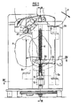
- la figure 1 est une élévation vue de face des parties essentielles du dispositif;
- la figure 2 est une couple axiale transversale selon II-II de la figure 1;
- la figure 3 est une vue de dessus du dispositif;
- la figure 4 est une coupe horizontale selon IV-IV de la figure 1;
- la figure 5 est une vue horizontale partielle selon V de la figure 3; et
- la figure 6 est une coupe horizontale partielle selon VI-VI de la figure 3.
- Figure 1 is a front view elevation of the essential parts of the device;
- Figure 2 is a transverse axial torque along II-II of Figure 1;
- Figure 3 is a top view of the device;
- Figure 4 is a horizontal section on IV-IV of Figure 1;
- Figure 5 is a partial horizontal view along V of Figure 3; and
- FIG. 6 is a partial horizontal section along VI-VI of FIG. 3.
On voit, notamment sur les figures 2 et 6, la toupie T selon l'invention qui comporte une surface 1 de révolution, dans ce cas cylindrique, susceptible de venir s'appuyer sur la surface du produit P à éplucher de manière à limiter la pénétration, cette surface ayant un très petit diamètre, par exemple de l'ordre de 20 mm. Par ailleurs, la toupie comporte un très petit nombre de saillies 2, par exemple deux pour assurer l'équilibrage en rotation. La toupie T avec sa surface d'appui 1 peut par exemple être en matière plastique moulée, tandis que les saillies 2 sont avantageusement constituées par la partie dépassante d'une lame métallique qui peut être affûtée ou non. La hauteur de dépassement de chaque saillie au-delà de la surface 1 définit la profondeur de passe maximum et peut éventuellement être modifiée en disposant de plusieurs types de toupie.We see, in particular in Figures 2 and 6, the router T according to the invention which has a surface 1 of revolution, in this case cylindrical, capable of coming to bear on the surface of the product P to be peeled so as to limit the penetration, this surface having a very small diameter, for example of the order of 20 mm. Furthermore, the router has a very small number of
Selon une caractéristique essentielle de l'invention, cette toupie tourne autour de son axe AT à une très grande vitesse de rotation, par exemple 20 000 t/minute, de manière que la vitesse tangentielle des saillies 2 soit au moins de l'ordre de 20 m/s, ou en tout cas supérieure à 8 m/s. Cette vitesse de rotation élevée ne nécessite par contre qu'un couple relativement faible, de sorte qu'elle peut aisément être assurée à l'aide d'un petit moteur 3 à entraînement direct placé à l'autre extrémité de l'arbe A d'axe AT. Toutefois, tout autre type de transmission, par exemple par courroie, ou d'entraînement, par exemple par turbine, serait utilisable.According to an essential characteristic of the invention, this router rotates around its axis AT at a very high speed of rotation, for example 20,000 rpm, so that the tangential speed of the
Conformément à l'invention, l'ensemble 4 comportant les paliers 5 et 6 de l'arbre A, et éventuellement le moteur 3 comme dans le case présent, ou l'organe récepteur de la transmission, est monté oscillant autour d'un axe d'oscillation AM perpendiculaire à AT. Cet axe AM est par exemple porté par une cage C en forme de chape, visible notamment sur les figures 3, 5 et 6, et montée elle-même tournante autour d'une axe AC qui est perpendiculaire à l'axe d'articulation moteur AM, et de préférence excentré, c'est-à-dire non concourant avec le précédent, comme on le voit en particulier sur la figure 6. En même temps, un couple de rappel, exercé par exemple par un ressort r, produit une rotation de l'ensemble 4 autour de cet axe pour produire au niveau de la toupie T un faible effort d'application de celle-ci sur le produit P, de l'ordre de 0,3 N ou au plus 0,5 N. En effet, la grande vitesse de rotation de la toupie ne nécessite pas une forte pression sur le produit.According to the invention, the assembly 4 comprising the
Le produit P lui-même, légume ou fruit, peut être entraîné d'un mouvement hélicoïdal pour assurer l'exploration systématique de sa surface par la toupie T, sans nécessiter non plus de grand couple d'entraînement en rotation ni de grande force d'entraînement en translation. Dans l'exemple représenté, ce double entraînement du produit P est assuré par une courte broche B dont l'extrémité est pointue et taillée en forme de vis à grand pas à la manière d'un tire-bouchon, de façon à pouvoir se visser directement dans une faible longueur du produit correspondant à la plus petite dimension en longueur des produits traités. De cette manière, la simple rotation de la broche B sur elle-même suffit pour assurer la pénétration de la broche dans le produit P, par exemple immobilisée momentanément à la main, puis dans un deuxième temps, l'entraînement en rotation et en translation de ce produit.The product P itself, vegetable or fruit, can be driven in a helical movement to ensure systematic exploration of its surface by the router T, without either requiring a large torque for rotation or great force d drive in translation. In the example shown, this double entrainment of the product P is ensured by a short pin B, the end of which is pointed and cut into the shape of a screw with large pitch in the manner of a corkscrew, so as to be able to be screwed directly in a short length of the product corresponding to the smallest dimension in length of the products treated. In this way, the simple rotation of the spindle B on itself is sufficient to ensure the penetration of the spindle into the product P, for example momentarily immobilized by hand, then in a second step, the drive in rotation and in translation of this product.
Dans l'exemple représenté, on dispose pour cela d'une vis verticale V, visible sur les figures 1 à 4, et qui est entraînée en rotation lente à partir d'une deuxième moteur 7 dans l'exemple représenté, par l'intermédiaire d'un démultiplication 8 appropriée située sous la base 9 de l'appareil, et entraînant l'extrémité inférieure de la vis V, de préférence par friction.In the example shown, there is available for this a vertical screw V, visible in Figures 1 to 4, and which is driven in slow rotation from a
Sur cette vis V est monté un chariot 10, visible en particulier sur les figures 2 et 4 et qui constitue un écrou susceptible de se déplacer en translation le long de la vis à la faveur de la rotation de celle-ci, dans un sens et dans l'autre. Ce cheriot 10 affecte la forme d'un bras dont l'extrémité porte les paliers 11 et 12 de la base de la broche B précédente. Une transmission appropriée permet de trasmettre le mouvement de rotation de la vis V à l'a broche B. Dans l'exemple représenté, cette transmission a lieu à l'aide d'une poulie 13, calée sur la broche B entre les paliers 11 et 12, et d'une courroie 14 qui passe directement entre deux filets de la vis V, ce qui assure tout à la fois l'entraînement par friction de la courroie et son cheminement longitudinal dans les mêmes conditions que le chariot 10. Toutefois, tout autre mode de transmission serait utilisable. Le rapport de transmission peut être égal à un ou différent de un.On this screw V is mounted a
En raison des frottements inévitables entre la vis V et le chariot 10, ainsi qu'entre la broche B et ses paliers 11 et 12 dont le couple est répercuté sur la vis par la courroie 14, et également de l'inertie et de la résistance à l'entraînement du produit P qui s'opposent au mouvement, lorsque la vis V est entraînée en rotation, le chariot 10 a tout naturellement tendance à tourner avec cette vis plutôt que de se déplacer en translation sur celle-ci. Pour assurer cette translation, on munit donc le chariot 10 d'un prolongement arrière 15 susceptible de venir buter et glisser verticalement sur une butée 16 solidaire du bâti de l'appareil lorsque la vis tourne dans le sens inverse des aiguilles d'une montre vue de dessus, et à venir de même buter et glisser verticalement contre une autre butée 17 solidaire du bâti lorsque la vis tourne dans le sens des aiguilles d'une montre. En outre, dans ce dernier cas, il est prévu également une butée intermédiaire 18 qui, comme on le voit sur la figure 2, ne s'étend que sur une faible partie de la hauteur.Due to the inevitable friction between the screw V and the
En particulier, lorsque le prolongement 15 du chariot se trouve en butée sur la butée 17, la vis tournant dans le sens des aiguilles d'une montre, la broche B se trouve en position 8, à la gauche de la figure 4, en desous de la toupie T et sensiblement à l'aplomb de celle-ci. La rotation lente de la vis V dans le sens indiqué produit donc l'avancement hélicoïdal vers le haut du produit P avec un pas correspondant exactement à celui de la vis V, divisé par le rapport de transmission indiqué ci-dessus, s'il y a lieu.In particular, when the
En même temps, selon l'invention, la cage C est positionnée au départ de telle manière qui l'axe d'articulation moteur AM soit incliné sensiblement à 45° par rapport à l'axe AB de la broche B, et dans un sens tel que la recontre de la toupie T avec le sommet du produit P produise la fuite oblique de la toupie dans le sens F qui l'éloigne de l'axe AB, comme représenté sur la figure 5. Ensuite, conformément à l'invention, l'axe AM doit tourner lentement autour de l'axe de cage AC jusqu'à dépasser la verticale et atteindre une inclinaison semblable et de sens inverse. Toutefois, cette deuxième inclinaison peut s'arrêter à une vingtaine de degrés environ par rapport à la verticale.At the same time, according to the invention, the cage C is positioned at the start in such a way that the motor articulation axis AM is inclined substantially at 45 ° relative to the axis AB of the spindle B, and in one direction. such as meeting the router T with the top of the product P produces the oblique leakage of the router in the direction F which moves it away from the axis AB, as shown in FIG. 5. Then, in accordance with the invention, the AM axis must rotate slowly around the cage axis AC until it exceeds the vertical and reaches a similar inclination and in the opposite direction. However, this second inclination can stop at about twenty degrees from the vertical.
Pendant ce mouvement, la toupie explore la surface entière du produit P en traçant des sillons parallèles dont le pas apparent est sensiblement égal à celui indiqué ci-dessus, le sens de rotation de la toupie T, représenté par la flèche S sur les figures 1 et 5, étant choisi de telle manière que la toupie attaque toujours la peau du produit P par en dessous en partant de la spire précédente déjà pelée. Ceci est particulièrement important pour les produits terreux, tels que pommes de terre ou carottes, pour éviter l'usure exagérée des saillies 2 et pour laisser le produit pelé P parfaitement propre.During this movement, the router explores the entire surface of the product P by drawing parallel grooves whose apparent pitch is substantially equal to that indicated above, the direction of rotation of the router T, represented by the arrow S in FIGS. 1 and 5, being chosen in such a way that the router always attacks the skin of the product P from below, starting from the previous turn already peeled. This is particularly important for earthy products, such as potatoes or carrots, to avoid excessive wear of the
Ce mouvement de rotation de la cage C autour de l'axe AC peut être produit par tout moyen approprié, continu ou discontinu, mais il peut être obtenu d'une manière très simple dans l'exemple représenté à l'aide d'une poulie 19 entraînant la cage C par friction et entraînée elle-même par une courroie 20 à partir de la vis V et par l'intermédiaire d'un couple à roue 21 et vis tangente 22, cette dernière étant portée en bout de la vis V. L'arbe 23 entraîné par la roue 21 entraîne par son autre extrémité la courroie 20.This rotational movement of the cage C around the axis AC can be produced by any suitable means, continuous or discontinuous, but it can be obtained in a very simple manner in the example shown using a
Lorsque la toupie T attaque la calotte supérieure du produit P, il y a intérêt à opérer bien au centre, selon l'axe AB, alors que lorsque la toupie termine l'épluchage du produit P au voisinage de la broche B, il y a intérêt à décaler la position de cette toupie par rapport à l'axe AB de cette broche de la quantité juste suffisante pour éviter la rencontre de la toupie avec la broche B ou le chariot 10. Ceci peut être obtenu très simplement dans le cas de l'invention en faisant coulisser l'ensemble de la cage C et de la poulie 19 le long de son axe AC, en prévoyant pour cela une came évolutive 24 prise entre un bossage 25 et un doigt 26 solidaires de la cage pour assurer, par ce double guidage, le recul progressif de l'ensemble et son retour en position initiale dans le mouvement inverse.When the router T attacks the upper cap of the product P, it is advantageous to operate well in the center, along the axis AB, while when the router finishes peeling the product P in the vicinity of the spindle B, there is interest in shifting the position of this router relative to the axis AB of this spindle by the quantity just sufficient to avoid the encounter of the router with spindle B or the
Par ailleurs, la longueur des produits P pouvant être très variable, le moment auquel doit commencer la rotation de la cage C autour de son axe AC doit être retardé jusqu'au contact effectif de la toupie T avec le produit P. Pour cela, il est prévu un guide sensiblement cylindrique 27, visible en particulier sur les figures 1,3,5 et 6, et sur le bord duquel vient porter un doigt de butée 28 limitant la course de basculement de l'ensemble 4 autour de l'axe AM. Dans la position de départ, ce doigt 28 pénètre au fond d'une encoche 30 du guide 27 et vient buter contre une butée 31 escamotable, qui s'oppose à la rotation de la cage C jusqu'au moment où, la toupie T ayant rencontré le produit et ayant été soulevé par celui-ci dans le sens F, le doigt 28 échappe de la butée 31 qui définissait la position de départ et commence sa rotation lente en fonction de l'entraînement indiqué.Furthermore, since the length of the products P can be very variable, the moment at which the rotation of the cage C around its axis AC must begin must be delayed until the effective contact of the router T with the product P. For this, it a substantially
Compte tenu du recul progressif de la poulie 19 comme exposé plus haut, la poulie d'entraînement solidaire de l'arbe 23 peut avantageusement être remplacée par un tronçon de vis hélicoïdale 32 comme dans l'exemple représenté, mais tout autre mode de transmission serait naturellement applicable. Naturellement, la position angulaire de la cage C en fin d'épluchage est définie par une simple butée angulaire opérant au niveau de la rampe 24 ou du guide 27.Given the progressive retraction of the
Le dispositif se complète avantageusement par une pelle de centrage 33, visible sur les figures 1 et 4 et articulée autour d'un axe 34 solidaire du bâti de l'appareil. Cette pelle comporte une partie concave 35 servant à centrer la base du produit à l'aplomb de la broche B lorsque celle-ci se trouve en position médiane, définie par la butée du prolongement arrière 15 du chariot 10 sur la butée intermédiaire 18. On voit d'autre part que la pelle 33 comporte une encoche de dégagement 36 permettant le passage de la base de la broche B lors de la rotation du chariot 10 de la position médiane à la position 81 sur la figure 4.The device is advantageously completed by a centering
On peut suivre le mouvement générale de l'appareil sur les figures, notamment sur la figure 1. On suppose, au départ, que l'appareil est arrêté dans la position représentée en traits pleins, c'est-à-dire avec le chariot 10 en position médiane et à l'extrémité inférieure de la course de la vis V. L'usager place alors à la main un produit P dans l'empreinte de centrage 35 et actionne une commande manuelle qui met en route le moteur 7. Cette commande manuelle peut simplement être constituée par un contact non représenté actionné par le début de déplacement de la pelle 33 vers le bas, déplacement durant lequel le produit vient s'appuyer par sa base sur la pointe de la broche B. Due fait de la rotation de la vis dans le sens des aiguilles d'une montre, et par l'intervention de la butée arrière 18, le chariot 10 monte verticalement, tourjours en position médiane, tandis que la broche B est entraînée dans le sens inverse des aiguilles d'une montre par la transmission 14 indiquée, ce qui produit automatiquement sa montée en même temps que son vissage dans le produit. Si le pas de la partie en tire-bouchon de la broche Be est sensiblement égal au pas de la vis V, compte tenu du rapport de transmission éventuel entre les deux axes, l'ascension de la broche se fait sans déplacement axial du produit, lequel est naturellement immobilisé en rotation par la main de l'opérateur.We can follow the general movement of the device in the figures, especially in Figure 1. It is assumed, at the outset, that the device is stopped in the position shown in solid lines, that is to say with the
Au bout d'une course déterminée du chariot 10, détectée par un contact d'arrêt approprié non représenté, la broche B s'est vissée exactement de toute sa longueur, et en même temps le prolongement arrière 15 du chariot 10 est venu à l'extrémité supérieure de la butée 18, sans toutefois échapper de celle-ci. Le moteur 7 est alors arrêté par ce contact d'arrêt.At the end of a determined stroke of the
Après avoir retiré sa main, l'opérateur actionne alors une autre commande manuelle qui peut par exemple être constituée par un supplément de course de la pelle 33, et un autre contact remet le moteur 7 en route, toujours dans le même sens, en court-circuitant par exemple le contact d'arrêt précédent. Dès que le chariot commence à monter, son prolongement arrière 15 échappe alors de la butée intermédiaire 18, de sorte que l'ensemble du chariot, 10, de la broche B, et du produit P porté par celle-ci, se met à tourner avec la vis jusqu'à intervention de la butée 17 comme exposé plus haut.After removing his hand, the operator then actuates another manual control which can for example consist of an additional stroke of the
Ensuite, toujours dans le même mouvement, le produit P entame son mouvement hélicoïdal vers le haut. En même temps, la toupie T tourne dans le sens indiqué, et la cage C, entraînée par friction par la poulie 19, reste néanmoins en position immobile, bloquée par le doigt 28 qui appuie sur la butée 31. Au bout d'un certain nombre de tours, qui dépend de la longueur du produit P, le sommet de celui-ci vient recontrer la toupie T, ce qui produit l'usinage d'une spirale d'épluchage sur sa calotte d'extrémité, en même temps que le dégagement du doigt 28 permettant la rotation ultérieure lente de la cage C autour de son axe AC comme exposé plus haut.Then, still in the same movement, the product P begins its helical movement upwards. At the same time, the router T rotates in the direction indicated, and the cage C, driven by friction by the
L'ascension du produit se continuant, la toupie explore sa surface en y traçant des spires qui passent d'une spirale quasiment plane à des spires quasiment hélicoïdales, pour se terminer à l'autre extrémité à nouveau par une spirale sensiblement plane, toutes ces spires ayant un pas apparent relativement constant grâce à la variation progressive de l'inclinaison de l'axe AM comme indiqué plus haut. En même temps, comme on l'a vu, le recul progressif de la cage C permet à la toupie T d'éviter de recontrer la broche B, cette dernière comportant, par ailleurs, une partie non filetée à sa base d'une longueur sensiblement égale au diamètre de cette toupie pour éviter la recontre de cette dernière avec le chariot.The ascent of the product continuing, the router explores its surface by tracing turns which pass from an almost planar spiral to almost helical turns, to end at the other end again by a substantially planar spiral, all these turns having a relatively constant apparent pitch thanks to the progressive variation of the inclination of the AM axis as indicated above. At the same time, as we have seen, the progressive retraction of the cage C allows the router T to avoid encountering the spindle B, the latter comprising, moreover, a non-threaded part at its base with a length substantially equal to the diameter of this router to avoid meeting it with the carriage.
Le retour de la toupie au voisinage de l'axe AB s'opère pour la position du chariot 10 correspondant au sommet de sa course, position indépendante de la longueur du produit P et qui est déterminée par un contact de fin de course supérieure non représenté.The return of the router to the vicinity of the axis AB takes place for the position of the
L'actionnement de ce contact produit simplement l'inversion de marche du moteur 7, le moteur 3, s'il y a lieu, pouvant indifféremment continuer dans le même sens, ou être arrêté, ou inverser sa marche. Cette inversion de sens de rotation de la vis V produit alors l'entraînement du chariot de la gauche vers la droite de la figure 1 jusqu'à la position représentée par B2 sur la figure 4. Dans cette position, et comme représenté sur la figure 3, la base non filetée de la broche B vient s'engager dans l'échancrure 36 d'une poste d'évacuation constitué par une surface 37 horizontale ou inclinée, suivie d'une rampe 38 ou d'une goulotte d'évacuation.The actuation of this contact simply produces the reverse operation of the
Lorsque la broche B est à l'aplomb de cette nouvelle position, c'est-à-dire lorsque le prolongement arrière 15 du chariot 10 recontre la première butée 16, la broche B entame un mouvement hélicoïdal vers le bas dans le sens du dévissage.When the spindle B is perpendicular to this new position, that is to say when the
Le produit P est donc lui-même entraîné librement de ce mouvement halicoïdal jusqu'à ce que sa base vienne recontrer la surface d'appui 37 du poste d'évacuation. Ceci a pour effet de l'immobiliser par frottement, permettant, ainsi le dévissage de la broche B qui, une fois débarrassée du produit P, continue seule son mouvement descendant jusqu'à l'extrémité inférieure de la course.The product P is therefore itself driven freely by this halicoidal movement until its base comes into contact with the bearing
Là, un autre contact de fin de course inférieure, non représenté, produit à nouveau une inversion du sens de marche du moteur 7, ce qui entraîne l'ensemble du chariot 10 dans la position médiane B sur la figure 4, son prolongement arrière 15 venant en butée sur la butée intermédiaire 18. Un autre contact électrique non représenté, détectant l'arrivée de ce prolongement arrière i5 contre la butée 18 et en position basse, provoque l'arrêt du moteur 7, et éventuellement du moteur 3, l'appareil se retrouvant ainsi dans la position initiale du début de cycle. Naturellement, lors de ce dernier mouvement, la pointe supérieure de la broche B passe juste sous la pelle 33 pour venir se placer en dessous du fond de l'échancrure 36.There, another lower limit switch, not shown, again produces a reversal of the direction of movement of the
En réalité, tout l'ensemble du cycle d'épluchage qui vient d'être décrit s'enchaîne automatiquement et dure à peine un dizaine de seconds, ce temps étant utilisé par l'opérateur pour saisir un autre produit et le placer à nouveau dans la pelle de centrage.In reality, the whole of the peeling cycle which has just been described is linked automatically and lasts barely ten seconds, this time being used by the operator to grab another product and place it again in the centering shovel.
Pendant tout ce cycle d'épluchage, les particules de peau du produit P, finement déchiquetées par les saillies 2 de la toupie T, sont projetées tangentiellement vers une zone d'étendue réduit où leur accumulation ne risque en rien de gêner la marche de l'appareil. Naturellement, cette zone est de préférence ménagée en forme de réceptacle amovible, non représenté, permettant son nettoyage. Des dispositifs de protection classique, non représentés dans un but de simplification, permettent de protéger le mécanisme, notamment la vis, contre les projections accidentelles de salissure.During this entire peeling cycle, the skin particles of the product P, finely shredded by the
Dans la pratique, un même type de toupie peut servir pratiquement pour la plupart des produits, qu'il s'agisse de légumes à chair dure tels que carottes, ou de légumes à chair tendre tels que pommes de terre, ou encore de légumes à chair filandreuse tels que navets ou oignons, et également des fruits à pelure mince comme les pommes ou les poires. Du fait qu'aucune adaptation ni qu'aucun calibrage des produits n'est nécessaire, il est donc possible à l'usager d'enchaîner des produits différents, par exemple carottes, pommes de terre, navets, oignons, etc. sans avoir à changer quoi que ce soit à l'appareil. Pour ce qui concerne les fruits à peau épaisse, en particulier les oranges et les citrons, il est possible, comme on l'a vu plus haut, d'utiliser une toupe spéciale dont le dépassement des saillies 2 est plus important. Une autre solution est d'agir sur la vitesse relative de la toupie par rapport à la vitesse de la vis, ce qui est partiulièrement simple dans le case de l'exemple décrit où on dispose de deux moteurs indépendants 3 et 7. Enfin, une dernière solution consiste à recommencer plusieurs fois le cycle d'épluchage sur le même agrume. Cette dernière solution présente en outre l'avantage qu'au premier passage on peut, si on le désire, récupérer, le zeste du fruit dans le réceptacle indiqué ci-dessus, tandis qu'au ou aux passages suivants, on élimine la peau blanche.In practice, the same type of router can be used practically for most products, whether it is hard-fleshed vegetables such as carrots, or tender-fleshed vegetables such as potatoes, or vegetables stringy flesh such as turnips or onions, and also thin-skinned fruits such as apples or pears. Since no adaptation or calibration of the products is necessary, it is therefore possible for the user to chain different products, for example carrots, potatoes, turnips, onions, etc. without having to change anything on the device. As regards thick-skinned fruits, in particular oranges and lemons, it is possible, as we have seen above, to use a special toupe, the protrusion of the
Il faut enfin remarquer que, malgré l'absence d'eau dans l'appareil, tous les produits épluchés, fruits ou légumes, sortent du poste d'évacuation parfaitement propres grâce au mode d'épluchage utilisé et n'ont pratiquement pas besoin d'être nettoyés avant utilisation.Finally, it should be noted that, despite the absence of water in the appliance, all the peeled products, fruits or vegetables, leave the evacuation station perfectly clean thanks to the peeling method used and have practically no need for '' be cleaned before use.
Claims (11)
Priority Applications (1)
| Application Number | Priority Date | Filing Date | Title |
|---|---|---|---|
| AT86107938T ATE52672T1 (en) | 1985-06-26 | 1986-06-11 | PEELING MACHINE FOR FRUITS AND VEGETABLES. |
Applications Claiming Priority (2)
| Application Number | Priority Date | Filing Date | Title |
|---|---|---|---|
| FR8509737 | 1985-06-26 | ||
| FR8509737A FR2583969B1 (en) | 1985-06-26 | 1985-06-26 | FRUIT AND VEGETABLE Peeler |
Publications (2)
| Publication Number | Publication Date |
|---|---|
| EP0207334A1 EP0207334A1 (en) | 1987-01-07 |
| EP0207334B1 true EP0207334B1 (en) | 1990-05-16 |
Family
ID=9320697
Family Applications (1)
| Application Number | Title | Priority Date | Filing Date |
|---|---|---|---|
| EP86107938A Expired - Lifetime EP0207334B1 (en) | 1985-06-26 | 1986-06-11 | Peeler for fruits and vegetables |
Country Status (7)
| Country | Link |
|---|---|
| US (1) | US4765234A (en) |
| EP (1) | EP0207334B1 (en) |
| JP (1) | JPS623777A (en) |
| AT (1) | ATE52672T1 (en) |
| DE (1) | DE3671155D1 (en) |
| ES (1) | ES8707659A1 (en) |
| FR (1) | FR2583969B1 (en) |
Families Citing this family (32)
| Publication number | Priority date | Publication date | Assignee | Title |
|---|---|---|---|---|
| US4704959A (en) * | 1986-01-22 | 1987-11-10 | Scallen David J | Apparatus for cutting potatoes and onions |
| ES2012107A6 (en) * | 1988-07-07 | 1990-03-01 | Perez Gonzalvo Jose | Fruit peeler. |
| US4937088A (en) * | 1988-12-29 | 1990-06-26 | The Procter & Gamble Company | Method of and apparatus for extracting juice and meat from a fruit |
| IL97613A (en) * | 1990-03-22 | 1994-06-24 | Ser Gonzalez Clemente Del | Fruit-peeling machine |
| US5138940A (en) * | 1990-07-18 | 1992-08-18 | National Presto Industries, Inc. | Appliance for spirally slicing fruits and vegetables |
| US5089286A (en) * | 1990-07-18 | 1992-02-18 | National Presto Industries, Inc. | Appliance for spirally slicing fruits and vegetables |
| IT1262794B (en) * | 1993-06-09 | 1996-07-04 | Tiziana Tomelleri | MACHINE FOR THE AUTOMATIC PEELING OF OBLONG FRUITS, ADVANTAGEOUSLY OF KIWI |
| US5558011A (en) * | 1995-09-05 | 1996-09-24 | Heim; Stephen J. | Fruit paring and cutting apparatus |
| NL1004058C2 (en) * | 1996-09-18 | 1998-03-19 | Schaap Beheer B V B | Method and device for mechanically peeling potatoes. |
| US5690022A (en) * | 1996-12-11 | 1997-11-25 | Chai; Liao-Chu | Peeling device |
| US6053098A (en) * | 1999-09-17 | 2000-04-25 | Benriner Co., Ltd. | Rotary root vegetable slicer |
| US6523464B1 (en) | 2001-09-19 | 2003-02-25 | Ronald J. Widelo | Automated peeler |
| US6659522B2 (en) * | 2002-04-04 | 2003-12-09 | Hallie Anne Byth | Fruit and vegetable holding utensil |
| WO2004113033A1 (en) * | 2003-06-20 | 2004-12-29 | Hermanus Willem Van Heerden | A device for cutting a fruit or vegetable in a helical shape |
| JP3878593B2 (en) * | 2003-10-20 | 2007-02-07 | 株式会社ムロコーポレーション | Fruit vegetable peeler |
| US7278346B2 (en) * | 2005-07-22 | 2007-10-09 | Odom Jr Donald | Tourne cutting method, device and kit |
| US7913600B2 (en) * | 2005-07-22 | 2011-03-29 | Odom Jr Donald | Tourne cutting method and device |
| US9375858B2 (en) * | 2008-08-06 | 2016-06-28 | Edible Arrangements, Llc | Method and device for removing rinds from a food item |
| NL2004648C2 (en) * | 2010-05-03 | 2011-11-07 | Zti Mechatronics B V | DEVICE AND METHOD FOR PEELING CROPS. |
| CA2828950A1 (en) * | 2011-03-01 | 2012-09-07 | Zip Zester Llc | Device for extracting zest from a fruit, and related extraction methods |
| US9433224B2 (en) * | 2013-06-28 | 2016-09-06 | Hua Long | Poultry processing equipment |
| CN103494501A (en) * | 2013-09-10 | 2014-01-08 | 常熟市微尘电器有限公司 | Automatic fruit peeling machine |
| US11064913B2 (en) | 2013-10-25 | 2021-07-20 | Force Impact Technologies, Inc. | Impact sensing wearable device and method |
| US10820735B2 (en) | 2015-03-05 | 2020-11-03 | Whirlpool Corporation | Modular food processing and preparation device |
| USD815888S1 (en) | 2015-11-20 | 2018-04-24 | Andrea Vianello | Food cutter |
| USD901970S1 (en) | 2015-12-30 | 2020-11-17 | Whirlpool Corporation | Food processing device |
| CN107280440A (en) * | 2016-04-04 | 2017-10-24 | 白先术 | Pineapple melon and fruit skinning machine |
| US10045650B2 (en) | 2016-12-31 | 2018-08-14 | Frederic William Brady, JR. | DC rechargeable battery powered appliance purposed to remove a thin outer layer of skin from vegetables and fruits |
| EP3542647A1 (en) * | 2018-03-22 | 2019-09-25 | Lurch AG | Fruit peeling device |
| EP4070864A1 (en) | 2018-12-20 | 2022-10-12 | Force Impact Technologies, Inc. | Mouth guard having user-notification feature of impact force and method of making the same |
| USD907448S1 (en) * | 2019-07-17 | 2021-01-12 | Progressive International Corporation | Apple paring machine frame |
| FR3136147A1 (en) * | 2022-06-03 | 2023-12-08 | Seb S.A. | Culinary preparation device and apparatus for performing a helical cut on a fruit or vegetable |
Family Cites Families (9)
| Publication number | Priority date | Publication date | Assignee | Title |
|---|---|---|---|---|
| US1872731A (en) * | 1926-06-28 | 1932-08-23 | California Packing Corp | Fruit peeling machine |
| US3013595A (en) * | 1958-12-08 | 1961-12-19 | Fmc Corp | Apparatus for processing fruit |
| US3113603A (en) * | 1961-09-11 | 1963-12-10 | Fmc Corp | Rotary cutter for peeling fruit |
| FR1481314A (en) * | 1966-05-16 | 1967-05-19 | Atlas Pacifik Eng Co | Advanced cutting mechanism that can be used to peel pears and other fruits |
| GB1224205A (en) * | 1967-04-10 | 1971-03-03 | Atlas Pacifik Eng Co | Apparatus for peeling double indented fruit |
| US3680614A (en) * | 1971-02-09 | 1972-08-01 | Ralph Polk Jr | Fruit peeling knife assembly |
| US3881406A (en) * | 1973-11-28 | 1975-05-06 | Artemio R Perez | Apparatus for peeling fruit or vegetables |
| IT1024276B (en) * | 1974-10-16 | 1978-06-20 | Tomelleri Giordano | CUTTING MECHANISM WITH ROTATING TURNING FOR THE SHAPING OF THE BOTTOMS OF ARTICHOKE HEARTS |
| GB2037147A (en) * | 1978-12-11 | 1980-07-09 | Chen Shih Lin | Peeling-apparatus |
-
1985
- 1985-06-26 FR FR8509737A patent/FR2583969B1/en not_active Expired
-
1986
- 1986-06-11 AT AT86107938T patent/ATE52672T1/en not_active IP Right Cessation
- 1986-06-11 EP EP86107938A patent/EP0207334B1/en not_active Expired - Lifetime
- 1986-06-11 DE DE8686107938T patent/DE3671155D1/en not_active Expired - Lifetime
- 1986-06-24 US US06/877,769 patent/US4765234A/en not_active Expired - Fee Related
- 1986-06-25 ES ES556737A patent/ES8707659A1/en not_active Expired
- 1986-06-26 JP JP61150628A patent/JPS623777A/en active Pending
Also Published As
| Publication number | Publication date |
|---|---|
| FR2583969B1 (en) | 1987-09-11 |
| ES556737A0 (en) | 1987-08-16 |
| FR2583969A1 (en) | 1987-01-02 |
| DE3671155D1 (en) | 1990-06-21 |
| JPS623777A (en) | 1987-01-09 |
| EP0207334A1 (en) | 1987-01-07 |
| US4765234A (en) | 1988-08-23 |
| ATE52672T1 (en) | 1990-06-15 |
| ES8707659A1 (en) | 1987-08-16 |
Similar Documents
| Publication | Publication Date | Title |
|---|---|---|
| EP0207334B1 (en) | Peeler for fruits and vegetables | |
| EP0346392B1 (en) | Appliance for extracting juice and pulp from fruit and vegetables | |
| CA2404512C (en) | Rotating tool drive unit for food processing apparatus, and food processing apparatus equipped with same | |
| FR2834436A3 (en) | Fruit and vegetable juice extractor comprises disc cutter provided at top central area with radial rows of blades arranged in cross form and having end of one central blade extending across center of disc cutter | |
| EP0319556B1 (en) | Appliance for peeling fruit and vegetables | |
| FR2503545A1 (en) | PROCESS AND APPARATUS FOR FRUIT TILING, IN PARTICULAR TOMATOES | |
| EP0081466B1 (en) | Cheese grating apparatus | |
| FR2521836A1 (en) | TURNING MACHINE FOR VEGETABLES OR SIMILAR PRODUCTS | |
| EP1759600B1 (en) | Method and apparatus for trimming salads | |
| FR2692188A1 (en) | Peeling slicing and core removal form fruit and vegetables - rotation of product support drives assembly of peeling slicing and curing blades in translation | |
| FR2625379A1 (en) | DEVICE AND METHOD FOR SELECTIVE CUTTING OF MULTILAYERING OF OPTICAL OR ELECTRIC CABLE | |
| EP0114766B1 (en) | Kitchen device for processing food | |
| EP0086499B1 (en) | Apparatus for decorating pastry and bakery products | |
| FR2707844A1 (en) | Machine for cutting the bottoms out of artichokes | |
| FR2892289A1 (en) | Food e.g. carrot, processing apparatus for hotel industry, has elastic insert guiding food across spout and having tongues moved with respect to insertion axis of food in insert and supported perpendicularly against food | |
| BE502572A (en) | ||
| FR2508283A1 (en) | PROCESS AND APPARATUS FOR PRODUCING VEGETABLE PRODUCTS IN SPHERICAL FORM | |
| CH637040A5 (en) | Method and device for cleaning cheese rounds | |
| FR2469882A1 (en) | Automatic slicing of artichokes to isolate the core of the base - to produce tinned artichoke hearts without manual cutting | |
| WO1993005934A1 (en) | Mushroom slicer | |
| FR2647387A1 (en) | Method and apparatus for cutting shapes in vegetables and fruit | |
| FR3139440A1 (en) | Sleeve for coring head, and corresponding coring head | |
| BE399394A (en) | ||
| EP0060308B1 (en) | Mollusc, especially squid processing machine | |
| FR2667484A1 (en) | Method and machine for topping and tailing plants with elongated bulbs, and in particular shallots |
Legal Events
| Date | Code | Title | Description |
|---|---|---|---|
| PUAI | Public reference made under article 153(3) epc to a published international application that has entered the european phase |
Free format text: ORIGINAL CODE: 0009012 |
|
| AK | Designated contracting states |
Kind code of ref document: A1 Designated state(s): AT BE CH DE FR GB IT LI LU NL SE |
|
| 17P | Request for examination filed |
Effective date: 19870703 |
|
| 17Q | First examination report despatched |
Effective date: 19880823 |
|
| GRAA | (expected) grant |
Free format text: ORIGINAL CODE: 0009210 |
|
| AK | Designated contracting states |
Kind code of ref document: B1 Designated state(s): AT BE CH DE FR GB IT LI LU NL SE |
|
| PG25 | Lapsed in a contracting state [announced via postgrant information from national office to epo] |
Ref country code: AT Effective date: 19900516 Ref country code: SE Effective date: 19900516 Ref country code: NL Effective date: 19900516 |
|
| REF | Corresponds to: |
Ref document number: 52672 Country of ref document: AT Date of ref document: 19900615 Kind code of ref document: T |
|
| ITF | It: translation for a ep patent filed |
Owner name: BARZANO' E ZANARDO MILANO S.P.A. |
|
| REF | Corresponds to: |
Ref document number: 3671155 Country of ref document: DE Date of ref document: 19900621 |
|
| PG25 | Lapsed in a contracting state [announced via postgrant information from national office to epo] |
Ref country code: CH Effective date: 19900630 Ref country code: BE Effective date: 19900630 Ref country code: LU Free format text: LAPSE BECAUSE OF NON-PAYMENT OF DUE FEES Effective date: 19900630 Ref country code: LI Effective date: 19900630 |
|
| PG25 | Lapsed in a contracting state [announced via postgrant information from national office to epo] |
Ref country code: GB Effective date: 19900716 |
|
| GBT | Gb: translation of ep patent filed (gb section 77(6)(a)/1977) | ||
| NLV1 | Nl: lapsed or annulled due to failure to fulfill the requirements of art. 29p and 29m of the patents act | ||
| BERE | Be: lapsed |
Owner name: CAILLIOT SERGE Effective date: 19900630 |
|
| REG | Reference to a national code |
Ref country code: CH Ref legal event code: PL |
|
| PG25 | Lapsed in a contracting state [announced via postgrant information from national office to epo] |
Ref country code: DE Effective date: 19910301 |
|
| GBPC | Gb: european patent ceased through non-payment of renewal fee | ||
| PLBE | No opposition filed within time limit |
Free format text: ORIGINAL CODE: 0009261 |
|
| STAA | Information on the status of an ep patent application or granted ep patent |
Free format text: STATUS: NO OPPOSITION FILED WITHIN TIME LIMIT |
|
| PG25 | Lapsed in a contracting state [announced via postgrant information from national office to epo] |
Ref country code: FR Effective date: 19910430 |
|
| 26N | No opposition filed | ||
| REG | Reference to a national code |
Ref country code: FR Ref legal event code: ST |
|
| PG25 | Lapsed in a contracting state [announced via postgrant information from national office to epo] |
Ref country code: IT Free format text: LAPSE BECAUSE OF NON-PAYMENT OF DUE FEES;WARNING: LAPSES OF ITALIAN PATENTS WITH EFFECTIVE DATE BEFORE 2007 MAY HAVE OCCURRED AT ANY TIME BEFORE 2007. THE CORRECT EFFECTIVE DATE MAY BE DIFFERENT FROM THE ONE RECORDED. Effective date: 20050611 |
|
| PG25 | Lapsed in a contracting state [announced via postgrant information from national office to epo] |
Ref country code: FR Effective date: 19900630 |