EP0206355B1 - Vorrichtung zur Güteprüfung einer Widerstands-Schweissverbindung - Google Patents
Vorrichtung zur Güteprüfung einer Widerstands-Schweissverbindung Download PDFInfo
- Publication number
- EP0206355B1 EP0206355B1 EP86108832A EP86108832A EP0206355B1 EP 0206355 B1 EP0206355 B1 EP 0206355B1 EP 86108832 A EP86108832 A EP 86108832A EP 86108832 A EP86108832 A EP 86108832A EP 0206355 B1 EP0206355 B1 EP 0206355B1
- Authority
- EP
- European Patent Office
- Prior art keywords
- welding
- inlet opening
- electrode
- weld
- radiation detector
- Prior art date
- Legal status (The legal status is an assumption and is not a legal conclusion. Google has not performed a legal analysis and makes no representation as to the accuracy of the status listed.)
- Expired - Lifetime
Links
- 238000003908 quality control method Methods 0.000 title description 2
- 238000003466 welding Methods 0.000 claims description 62
- 230000005855 radiation Effects 0.000 claims description 26
- 230000003287 optical effect Effects 0.000 claims description 4
- 238000000034 method Methods 0.000 description 19
- 239000013307 optical fiber Substances 0.000 description 6
- 230000002123 temporal effect Effects 0.000 description 2
- 230000007423 decrease Effects 0.000 description 1
- 238000001514 detection method Methods 0.000 description 1
- 238000007689 inspection Methods 0.000 description 1
- 239000000463 material Substances 0.000 description 1
- 239000002184 metal Substances 0.000 description 1
Images
Classifications
-
- B—PERFORMING OPERATIONS; TRANSPORTING
- B23—MACHINE TOOLS; METAL-WORKING NOT OTHERWISE PROVIDED FOR
- B23K—SOLDERING OR UNSOLDERING; WELDING; CLADDING OR PLATING BY SOLDERING OR WELDING; CUTTING BY APPLYING HEAT LOCALLY, e.g. FLAME CUTTING; WORKING BY LASER BEAM
- B23K11/00—Resistance welding; Severing by resistance heating
- B23K11/24—Electric supply or control circuits therefor
- B23K11/25—Monitoring devices
Definitions
- the invention relates to a device for quality control and a resistance welded connection, in which a radiation detector is aligned with a welding point and receives the emitted radiation.
- Such a device has two problems that are closely related. On the one hand, it is necessary to arrange the radiation detector as close as possible to the welding point, since the radiation intensity emitted is low anyway and rapidly decreases after the welding process has ended. However, this creates the difficulty that the radiation detector is increasingly exposed to welding spatter, which at least partially closes its inlet opening and makes it increasingly ineffective.
- the invention has for its object to provide a device of the type mentioned, in which it is possible with structurally simple means to arrange the radiation detector as close as possible to the welding point, but without this being exposed to welding spatter. Furthermore, it should be possible to use the radiation detector to record a thermal image of the welding point immediately after the end of the welding process.
- the invention solves this problem in that the inlet opening of the radiation detector is already aligned with the welding point during the actual welding process, but is essentially covered for the purpose of protection against welding spatter, and is released after the welding process has ended.
- the welding electrode can be moved relative to the radiation detector with respect to the welding point.
- the optical connection between the welding point and the inlet opening existing before and after the welding process is only interrupted by the welding electrode during the welding process.
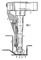
- An optical fiber optic 4 is attached to the holder 2 via a support part 3, the inlet opening 5 of which is arranged laterally above the cap 6 of the electrode 1.
- Infrared radiation falling into the entry opening passes via the optical fiber optics 4 to a radiation converter, also not shown, whose output signals are a measure of the radiation intensity falling into the entry opening and thus of the quality of a examined welding spot. The quality can be determined by comparing the measured radiation intensity with a reference value.
- the electrode 1 is moved with its cap 6 to a weld 9 and the welding process is carried out.
- the optical fiber optic 4 moved with the electrode 1 is arranged and aligned in such a way that it is protected by the cap 6 itself from welding spatter originating from the welding point 9 during the welding process, in which the cap 6 has the position 6 'shown in broken lines .
- the inlet opening 5 sits at the point 5 '.
- the electrode 1 lifts off from the welding point 9.
- the orientation of the inlet opening 5 with respect to the welding point 9 changes on the one hand and on the other hand the cap 6 exposes the “view” of the inlet opening 5 to the welding point 9.
- the radiation emanating from there preferably in the form of IR radiation, can now enter the inlet opening 5 and thus via the optical fiber optics 4 to the radiation converter. This means that the quality check of the welded joint can be carried out immediately after the welding process has ended.
- the inlet opening 5 always remains protected against welding spatter even when the electrode 1 is used for a long time. The quality inspection of welded joints can thus be carried out over the same period of use without further precautions.
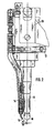
- the welding electrode 11 is movable relative to the holder 12.
- a corresponding optical fiber optic 14 with its inlet opening 15 is attached to the holder 12.
- the electrode 11 is moved together with the Holder 12 brought just above the intended welding point 19.
- the inlet opening 15 of the optical fiber optics 14 is aligned with the welding point 19.
- the electrode 11 is now moved by a cylinder 20 relative to the fixed holder 12 onto the welding point 19.
- the cap 16 of the electrode 11 slides into the optical connection between the inlet opening 15 and the welding point 19 and interrupts this connection. Welding spatter starting from the welding point 19 can then no longer get into the inlet opening 15 since the tip 16 shields this inlet opening 15.
- the electrode 11 is lifted off the welding point 19.
- the inlet opening 15, which is still at the same point is again given an optical connection with the welding point 19 and can absorb the radiation emanating from there.
- the electrode 11 shields the inlet opening 15 from welding spatter during the welding process.
Landscapes
- Engineering & Computer Science (AREA)
- Mechanical Engineering (AREA)
- Resistance Welding (AREA)
- Welding Or Cutting Using Electron Beams (AREA)
- Manufacturing Of Electrical Connectors (AREA)
Applications Claiming Priority (2)
| Application Number | Priority Date | Filing Date | Title |
|---|---|---|---|
| DE3523112 | 1985-06-28 | ||
| DE19853523112 DE3523112A1 (de) | 1985-06-28 | 1985-06-28 | Vorrichtung zur guetepruefung einer widerstands-schweissverbindung |
Publications (3)
| Publication Number | Publication Date |
|---|---|
| EP0206355A2 EP0206355A2 (de) | 1986-12-30 |
| EP0206355A3 EP0206355A3 (en) | 1988-01-13 |
| EP0206355B1 true EP0206355B1 (de) | 1990-02-21 |
Family
ID=6274409
Family Applications (1)
| Application Number | Title | Priority Date | Filing Date |
|---|---|---|---|
| EP86108832A Expired - Lifetime EP0206355B1 (de) | 1985-06-28 | 1986-06-28 | Vorrichtung zur Güteprüfung einer Widerstands-Schweissverbindung |
Country Status (4)
| Country | Link |
|---|---|
| US (1) | US4782230A (enExample) |
| EP (1) | EP0206355B1 (enExample) |
| DE (2) | DE3523112A1 (enExample) |
| ES (1) | ES8707339A1 (enExample) |
Families Citing this family (5)
| Publication number | Priority date | Publication date | Assignee | Title |
|---|---|---|---|---|
| DE4311320A1 (de) * | 1993-04-06 | 1994-10-13 | Branson Ultraschall | Verfahren und Vorrichtung zur Kontrolle der Schweißnahtqualität bei der Verbindung von Kunststoffteilen |
| US5414247A (en) * | 1993-12-29 | 1995-05-09 | The Boeing Company | Hot melt induction heater and method |
| DE4408291C2 (de) * | 1994-03-11 | 1997-04-10 | Abb Patent Gmbh | Verfahren zur automatisierten optischen Prüfung einer Schweißnaht eines Bauteils unter Anwendung des Lichtschnittverfahrens |
| US5968376A (en) * | 1998-08-19 | 1999-10-19 | Trw Inc. | Method for infrared inspection of resistence welds during assembling of an inflator |
| AT413665B (de) * | 2002-09-06 | 2006-04-15 | Fronius Int Gmbh | Verfahren zur qualitätsüberwachung von punktschweissungen |
Family Cites Families (11)
| Publication number | Priority date | Publication date | Assignee | Title |
|---|---|---|---|---|
| US2899563A (en) * | 1959-08-11 | stellmacher etal | ||
| US2817747A (en) * | 1955-04-19 | 1957-12-24 | Mckinnon Chain Corp | Method and apparatus for electric resistance welding |
| US3191441A (en) * | 1962-09-04 | 1965-06-29 | Sperry Rand Corp | Weld quality monitoring device for welding machines |
| CH545163A (de) * | 1972-05-31 | 1973-12-15 | Bbc Brown Boveri & Cie | Verfahren und Einrichtung zur Überwachung von elektrischen Widerstandsschweissungen |
| FR2248753A5 (enExample) * | 1973-10-23 | 1975-05-16 | France Etat | |
| DE2651878A1 (de) * | 1976-11-13 | 1978-05-18 | Daimler Benz Ag | Verfahren zum betrachten oder optischen registrieren eines objektes |
| FR2371685A1 (fr) * | 1976-11-17 | 1978-06-16 | Aerospatiale | Procede et dispositif pour le controle de la qualite de points de soudure par resistance |
| GB2018471B (en) * | 1978-03-23 | 1982-07-21 | Boc Ltd | Controlling depth of weld penetration |
| US4214164A (en) * | 1978-07-19 | 1980-07-22 | Vanzetti Infrared & Computer System Incorporated | Control of spot weld quality by infrared thermal sensing |
| US4359622A (en) * | 1980-05-19 | 1982-11-16 | Vanzetti Infrared & Computer Systems, Inc. | Controller for spot welding |
| US4408827A (en) * | 1981-09-02 | 1983-10-11 | United Technologies Corporation | Imaging system for hostile environment optical probe |
-
1985
- 1985-06-28 DE DE19853523112 patent/DE3523112A1/de active Granted
-
1986
- 1986-06-24 ES ES556515A patent/ES8707339A1/es not_active Expired
- 1986-06-27 US US06/879,631 patent/US4782230A/en not_active Expired - Fee Related
- 1986-06-28 DE DE8686108832T patent/DE3669068D1/de not_active Expired - Lifetime
- 1986-06-28 EP EP86108832A patent/EP0206355B1/de not_active Expired - Lifetime
Also Published As
| Publication number | Publication date |
|---|---|
| DE3523112A1 (de) | 1987-01-08 |
| DE3523112C2 (enExample) | 1987-11-26 |
| US4782230A (en) | 1988-11-01 |
| DE3669068D1 (de) | 1990-03-29 |
| ES556515A0 (es) | 1987-08-01 |
| EP0206355A3 (en) | 1988-01-13 |
| ES8707339A1 (es) | 1987-08-01 |
| EP0206355A2 (de) | 1986-12-30 |
Similar Documents
| Publication | Publication Date | Title |
|---|---|---|
| DE69108549T2 (de) | Laserbearbeitungsvorrichtung zum Schweissen und Schneiden. | |
| DE69012307T3 (de) | Apparat zum Schweissen von Kraftfahrzeugkarosserien. | |
| DE69837379T2 (de) | Verfahren und Vorrichtung zur Prüfung des Zustandes eines Schutzglases bei der Laserbearbeitung | |
| EP0134534B1 (de) | Aussen an einem Rohr ansetzbarer Prüfmanipulator | |
| CH648130A5 (de) | Optische vorrichtung mit einer lichtquelle und einer linse. | |
| DD201826A5 (de) | Optisches system zur erzeugung eines kollimierten lichtbuendels | |
| EP0206355B1 (de) | Vorrichtung zur Güteprüfung einer Widerstands-Schweissverbindung | |
| WO1983002156A1 (fr) | Dispositif pour la mesure de la temperature des parois d'un four a coke | |
| DE2653298A1 (de) | Pruefvorrichtung zum pruefen der enden von zigaretten | |
| EP0502421A2 (de) | Rauchabsaugvorrichtung an einem Schweissbrenner | |
| DE2831517C3 (de) | Tragbare Einheit zum Schweißen oder Löten | |
| EP0111215A1 (de) | Vorrichtung zur dreidimensionalen Bestimmung der Relativbewegung zwischen einem ersten und einem zweiten Körper | |
| DE3511474A1 (de) | Fotoelektrische fuehlvorrichtung mit lichtreflexion und/oder lichtschranke | |
| DE3741191A1 (de) | Vorrichtung zum ermitteln krummer schnitte zur verwendung bei einer bandsaege | |
| DE2918905C2 (de) | Röntgenapparat für medizinische Zwecke mit einem Röntgenbelichtungsautomaten | |
| DE1948042A1 (de) | Temperatur-Messvorrichtung | |
| DE3443493C2 (enExample) | ||
| DE4210555C2 (de) | Vorsatzoptik für eine Kamera | |
| DE1523282A1 (de) | Verfahren zur Temperaturregelung | |
| DE918544C (de) | Zum Zusammeschweissen von Rohren auf der Baustelle dienender Ring | |
| EP0653095B1 (de) | Einrichtung zur prüfung von stutzenschweissnähten | |
| DE1771763U (de) | Geraet zur linienweisen abtastung mit einer halbzylinderlinse. | |
| DE4203667A1 (de) | Verfahren und einrichtung zum erfassen und positionieren der nahtfuge fuer das laserschweissen | |
| DE3024679A1 (de) | Optisches kantenerkennungsgeraet | |
| DE1598941C3 (enExample) |
Legal Events
| Date | Code | Title | Description |
|---|---|---|---|
| PUAI | Public reference made under article 153(3) epc to a published international application that has entered the european phase |
Free format text: ORIGINAL CODE: 0009012 |
|
| AK | Designated contracting states |
Kind code of ref document: A2 Designated state(s): DE FR GB IT SE |
|
| PUAL | Search report despatched |
Free format text: ORIGINAL CODE: 0009013 |
|
| AK | Designated contracting states |
Kind code of ref document: A3 Designated state(s): DE FR GB IT SE |
|
| 17P | Request for examination filed |
Effective date: 19880224 |
|
| 17Q | First examination report despatched |
Effective date: 19880503 |
|
| GRAA | (expected) grant |
Free format text: ORIGINAL CODE: 0009210 |
|
| AK | Designated contracting states |
Kind code of ref document: B1 Designated state(s): DE FR GB IT SE |
|
| GBT | Gb: translation of ep patent filed (gb section 77(6)(a)/1977) | ||
| REF | Corresponds to: |
Ref document number: 3669068 Country of ref document: DE Date of ref document: 19900329 |
|
| ET | Fr: translation filed | ||
| ITF | It: translation for a ep patent filed | ||
| PG25 | Lapsed in a contracting state [announced via postgrant information from national office to epo] |
Ref country code: GB Effective date: 19900628 |
|
| PG25 | Lapsed in a contracting state [announced via postgrant information from national office to epo] |
Ref country code: SE Effective date: 19900629 |
|
| PLBE | No opposition filed within time limit |
Free format text: ORIGINAL CODE: 0009261 |
|
| STAA | Information on the status of an ep patent application or granted ep patent |
Free format text: STATUS: NO OPPOSITION FILED WITHIN TIME LIMIT |
|
| 26N | No opposition filed | ||
| GBPC | Gb: european patent ceased through non-payment of renewal fee | ||
| PG25 | Lapsed in a contracting state [announced via postgrant information from national office to epo] |
Ref country code: FR Effective date: 19910228 |
|
| PG25 | Lapsed in a contracting state [announced via postgrant information from national office to epo] |
Ref country code: DE Effective date: 19910301 |
|
| REG | Reference to a national code |
Ref country code: FR Ref legal event code: ST |
|
| EUG | Se: european patent has lapsed |
Ref document number: 86108832.6 Effective date: 19910207 |
|
| PG25 | Lapsed in a contracting state [announced via postgrant information from national office to epo] |
Ref country code: IT Free format text: LAPSE BECAUSE OF NON-PAYMENT OF DUE FEES;WARNING: LAPSES OF ITALIAN PATENTS WITH EFFECTIVE DATE BEFORE 2007 MAY HAVE OCCURRED AT ANY TIME BEFORE 2007. THE CORRECT EFFECTIVE DATE MAY BE DIFFERENT FROM THE ONE RECORDED. Effective date: 20050628 |