EP0205805A1 - Support disposé entre le carter inférieur d'un moteur à piston et la fondation d'un navire - Google Patents
Support disposé entre le carter inférieur d'un moteur à piston et la fondation d'un navire Download PDFInfo
- Publication number
- EP0205805A1 EP0205805A1 EP86105455A EP86105455A EP0205805A1 EP 0205805 A1 EP0205805 A1 EP 0205805A1 EP 86105455 A EP86105455 A EP 86105455A EP 86105455 A EP86105455 A EP 86105455A EP 0205805 A1 EP0205805 A1 EP 0205805A1
- Authority
- EP
- European Patent Office
- Prior art keywords
- foundation
- thrust
- cover plate
- plate
- ship
- Prior art date
- Legal status (The legal status is an assumption and is not a legal conclusion. Google has not performed a legal analysis and makes no representation as to the accuracy of the status listed.)
- Granted
Links
- 239000002184 metal Substances 0.000 claims abstract description 6
- 229910052751 metal Inorganic materials 0.000 claims abstract description 6
- 238000002485 combustion reaction Methods 0.000 claims abstract description 4
- 230000000284 resting effect Effects 0.000 claims abstract description 3
- 239000011347 resin Substances 0.000 description 3
- 229920005989 resin Polymers 0.000 description 3
- 238000005266 casting Methods 0.000 description 2
- 150000001875 compounds Chemical class 0.000 description 2
- 229910001060 Gray iron Inorganic materials 0.000 description 1
- 230000002411 adverse Effects 0.000 description 1
- 238000005452 bending Methods 0.000 description 1
- 238000010276 construction Methods 0.000 description 1
- 238000009434 installation Methods 0.000 description 1
- 238000012432 intermediate storage Methods 0.000 description 1
- 238000004519 manufacturing process Methods 0.000 description 1
- 230000036316 preload Effects 0.000 description 1
Images


Classifications
-
- B—PERFORMING OPERATIONS; TRANSPORTING
- B63—SHIPS OR OTHER WATERBORNE VESSELS; RELATED EQUIPMENT
- B63H—MARINE PROPULSION OR STEERING
- B63H21/00—Use of propulsion power plant or units on vessels
- B63H21/30—Mounting of propulsion plant or unit, e.g. for anti-vibration purposes
- B63H21/305—Mounting of propulsion plant or unit, e.g. for anti-vibration purposes with passive vibration damping
Definitions
- the invention relates to a support between a base plate containing an axial thrust bearing of an axially thrust-loaded piston internal combustion engine, in particular a drive machine for a ship's propeller, and the cover plate of the ship's foundation, the base plate of the machine resting on the foundation cover plate via fitting pieces made of metal or plastic and with With the help of foundation screws, each is connected to the foundation with a snug fit.
- connection described The main disadvantage of the connection described is that fit fits have to be worked into the cover plate in the hull, which is tedious and time-consuming.
- the object of the invention is to reduce the effort for the production of the fit-seat connections in the aforementioned type of support between the drive and the hull.
- This object is achieved according to the invention in that the support is provided by vertically extending thrust plates which are welded onto the foundation cover plate and which are bent at an angle and are connected in their free leg to the foot of the base plate in their free leg by means of fitting sleeves receiving the foundation bolts.
- the fit is in this way laid in a fitting sleeve which is inserted into the thrust plate; the whole fit-fit connection can thus be prefabricated in the factory - both in the base plate and in the sleeve.
- the thrust plate is bent out of the direction of the axial thrust load on its foot welded to the cover plate.
- a resulting reduction in the elastic flexibility of the thrust plates in the vertical direction can be counteracted if the thrust plate is cut out in the region of the bends.
- the stiffness of the thrust plates in the axial thrust direction in the area of the bent feet can be increased if the bent feet of the thrust plate are connected by a horizontal stiffening plate.
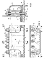
- an axial thrust bearing 2 is installed, which Axial thrust - arrow 3 - exerted by the ship's propeller, also not shown.
- This thrust force 3 is transmitted via a thrust ring 4 on the crankshaft 5 to the thrust bearing 2 and half of it is passed on to the side of the base plate 1 into the cover plate 6 of the ship's foundation 7.
- the base plate 1 lies on the cover plate 6 via a plastic compound 8 (FIGS. 1-4) or individual metal fitting pieces 9 (FIGS. 5-7).
- the metal fitting pieces 9 are made of gray cast iron, for example, and are adjusted in height so that the top of the base plate forms a horizontal surface.
- the fitting pieces 9 are in a known manner individual, relatively small blocks in the immediate area of the foundation bolts 10.
- a precise fit between the base plate 1 and the foundation cover plate 6 is ensured by a fitting sleeve 14, which is also penetrated by the screw 10 with play.
- the sleeve 14 is, on the one hand, fitted into a bore 15 (FIGS. 4 and 7) of the base plate foot 12 and, on the other hand, into thrust plates 16 bent into the horizontal, one of which is arranged symmetrically to the shaft 5 on both sides of the base plate 1.
- the thrust plate 16 is welded onto the foundation cover plate 6 with a vertical leg. With this construction it is achieved on the one hand that the fit seats 17 and 18 (FIGS. 4 and 17) in the base plate base 12 and in the thrust plate 16 can be prefabricated in the factory; on the other hand, the relatively "wide” arc of the thrust plate 16 enables elastic flexibility in the vertical direction, with which, after the plastic intermediate layer 8 has been set, the nuts can be "re-tensioned” by tightening the nuts 11.
- the feet 19 of the vertical legs of the thrust plates 16 welded onto the cover plate 6 are bent inwards (FIG. 3) or outwards (FIG. 6) from the shear stress direction 3.
- the plates 16 are provided with recesses 20 in the region of the bends, as can be seen particularly from FIGS. 2 and 5.
- a horizontal stiffening plate 21 is welded between the feet 19 of a thrust plate 16, through which the tips of the thrust loads of the thrust plates welded onto the cover plate 6 are distributed from the ends over the entire length of the weld seam 22 (FIGS. 4 and 7) will.
Landscapes
- Chemical & Material Sciences (AREA)
- Engineering & Computer Science (AREA)
- Combustion & Propulsion (AREA)
- Mechanical Engineering (AREA)
- Ocean & Marine Engineering (AREA)
- Shafts, Cranks, Connecting Bars, And Related Bearings (AREA)
- Pistons, Piston Rings, And Cylinders (AREA)
- Compressor (AREA)
- Connection Of Plates (AREA)
- Cylinder Crankcases Of Internal Combustion Engines (AREA)
Applications Claiming Priority (2)
| Application Number | Priority Date | Filing Date | Title |
|---|---|---|---|
| CH2575/85 | 1985-06-18 | ||
| CH257585 | 1985-06-18 |
Publications (2)
| Publication Number | Publication Date |
|---|---|
| EP0205805A1 true EP0205805A1 (fr) | 1986-12-30 |
| EP0205805B1 EP0205805B1 (fr) | 1988-12-07 |
Family
ID=4236882
Family Applications (1)
| Application Number | Title | Priority Date | Filing Date |
|---|---|---|---|
| EP19860105455 Expired EP0205805B1 (fr) | 1985-06-18 | 1986-04-19 | Support disposé entre le carter inférieur d'un moteur à piston et la fondation d'un navire |
Country Status (5)
| Country | Link |
|---|---|
| EP (1) | EP0205805B1 (fr) |
| JP (1) | JPS61291298A (fr) |
| DE (2) | DE3522188A1 (fr) |
| DK (1) | DK159870C (fr) |
| NO (1) | NO160425C (fr) |
Cited By (2)
| Publication number | Priority date | Publication date | Assignee | Title |
|---|---|---|---|---|
| WO1996033911A1 (fr) * | 1995-04-24 | 1996-10-31 | New Sulzer Diesel Ag | Dispositif permettant de transmettre des forces de poussee |
| CN114954837A (zh) * | 2022-06-20 | 2022-08-30 | 广船国际有限公司 | 一种船舶主机座面板与钢垫片拂配的方法和船舶 |
Families Citing this family (2)
| Publication number | Priority date | Publication date | Assignee | Title |
|---|---|---|---|---|
| JPS63194098U (fr) * | 1987-06-02 | 1988-12-14 | ||
| DE4138708C2 (de) * | 1991-11-26 | 2000-11-23 | Blohm & Voss Ind Gmbh | Anordnung zur elastischen Lagerung eines kombinierten Druck- und Traglagers, insbesondere für eine Schiffsantriebsanlage |
Citations (4)
| Publication number | Priority date | Publication date | Assignee | Title |
|---|---|---|---|---|
| US2431931A (en) * | 1944-09-14 | 1947-12-02 | Churchward & Company Inc | Engine mounting |
| DE852050C (de) * | 1941-05-03 | 1952-10-09 | Kloeckner Humboldt Deutz Ag | Sicherheitseinrichtung an Maschinenlagerungen fuer seegehende Schiffe |
| DE2230528B1 (de) * | 1972-06-22 | 1973-07-12 | Maschinenfabrik Augsburg-Nuernberg Ag, 8900 Augsburg | Elastisch gelagerte Brennkraftmaschine |
| DE3437318A1 (de) * | 1984-10-11 | 1986-04-17 | Aleksandr Aleksandrovič Aleksandrov | Verfahren zur aufstellung eines schiffs-kreuzkopf-hauptmotors auf dem fundament |
Family Cites Families (3)
| Publication number | Priority date | Publication date | Assignee | Title |
|---|---|---|---|---|
| GB501161A (en) * | 1937-11-02 | 1939-02-22 | Silentbloc | Improvements in or relating to apparatus for supporting engines |
| GB1469771A (en) * | 1973-05-02 | 1977-04-06 | English Electric Co Ltd | Support means |
| JPS5316781A (en) * | 1977-08-01 | 1978-02-16 | Mitsubishi Petrochem Co Ltd | Preparaion of resin laminate |
-
1985
- 1985-06-21 DE DE19853522188 patent/DE3522188A1/de active Granted
-
1986
- 1986-04-19 EP EP19860105455 patent/EP0205805B1/fr not_active Expired
- 1986-04-19 DE DE8686105455T patent/DE3661353D1/de not_active Expired
- 1986-05-19 JP JP11447486A patent/JPS61291298A/ja active Pending
- 1986-05-20 DK DK234786A patent/DK159870C/da not_active IP Right Cessation
- 1986-06-17 NO NO862410A patent/NO160425C/no unknown
Patent Citations (4)
| Publication number | Priority date | Publication date | Assignee | Title |
|---|---|---|---|---|
| DE852050C (de) * | 1941-05-03 | 1952-10-09 | Kloeckner Humboldt Deutz Ag | Sicherheitseinrichtung an Maschinenlagerungen fuer seegehende Schiffe |
| US2431931A (en) * | 1944-09-14 | 1947-12-02 | Churchward & Company Inc | Engine mounting |
| DE2230528B1 (de) * | 1972-06-22 | 1973-07-12 | Maschinenfabrik Augsburg-Nuernberg Ag, 8900 Augsburg | Elastisch gelagerte Brennkraftmaschine |
| DE3437318A1 (de) * | 1984-10-11 | 1986-04-17 | Aleksandr Aleksandrovič Aleksandrov | Verfahren zur aufstellung eines schiffs-kreuzkopf-hauptmotors auf dem fundament |
Cited By (4)
| Publication number | Priority date | Publication date | Assignee | Title |
|---|---|---|---|---|
| WO1996033911A1 (fr) * | 1995-04-24 | 1996-10-31 | New Sulzer Diesel Ag | Dispositif permettant de transmettre des forces de poussee |
| CN1071669C (zh) * | 1995-04-24 | 2001-09-26 | 瓦特西拉Nsd施韦兹公司 | 传递推力的装置 |
| CN114954837A (zh) * | 2022-06-20 | 2022-08-30 | 广船国际有限公司 | 一种船舶主机座面板与钢垫片拂配的方法和船舶 |
| CN114954837B (zh) * | 2022-06-20 | 2023-10-13 | 广船国际有限公司 | 一种船舶主机座面板与钢垫片拂配的方法和船舶 |
Also Published As
| Publication number | Publication date |
|---|---|
| DE3661353D1 (en) | 1989-01-12 |
| NO160425B (no) | 1989-01-09 |
| DE3522188C2 (fr) | 1987-05-27 |
| DK234786A (da) | 1986-12-19 |
| DK159870C (da) | 1991-05-21 |
| DE3522188A1 (de) | 1986-12-18 |
| JPS61291298A (ja) | 1986-12-22 |
| NO862410D0 (no) | 1986-06-17 |
| EP0205805B1 (fr) | 1988-12-07 |
| NO862410L (no) | 1986-12-19 |
| NO160425C (no) | 1989-04-19 |
| DK159870B (da) | 1990-12-24 |
| DK234786D0 (da) | 1986-05-20 |
Similar Documents
| Publication | Publication Date | Title |
|---|---|---|
| DE19604547B4 (de) | Gehäuse für eine Hubkolbenbrennkraftmaschine | |
| DE69716364T2 (de) | Kupplungsmethode und Kupplungsvorrichtung | |
| EP1032737B1 (fr) | Support de mandrin a force de cisaillement | |
| DE3810188A1 (de) | Laufschiene zum spannen einer transmission | |
| EP0205805B1 (fr) | Support disposé entre le carter inférieur d'un moteur à piston et la fondation d'un navire | |
| WO2001029447A1 (fr) | Ensemble d'arbres de compensation pour moteurs a piston alternatif | |
| DE2456379A1 (de) | Druckbehaelter, insbesondere kernreaktordruckbehaelter | |
| DE1531756B1 (de) | Wassergeschmiertes Lager fuer eine Schiffspropellerwelle | |
| DE69915981T2 (de) | Justierbares Fundament für Maschineneinheiten auf Schiffen | |
| DE2451012A1 (de) | Wellenanordnung fuer schiffe | |
| DE4024313A1 (de) | Versteifter aufbau des zylinderblocks eines verbrennungsmotors | |
| DE69405925T2 (de) | Vorrichtung zur Kompensation eines Lagefehlers eines Antriebsystems auf einer Brennkraftmaschine | |
| DE2744474A1 (de) | Endanschluss- bzw. kupplungsvorrichtung fuer ein aus armiertem beton oder spannbeton hergestelltes bauelement | |
| DE1218049B (de) | Elektrische Maschine mit vertikal angeordneter Welle und einem Staendergehaeuse aus Beton | |
| DE19801882C2 (de) | Maschinenfundamentplatte | |
| DE2905346A1 (de) | Spurrollenanordnung | |
| DE3930514A1 (de) | Schiffsantriebsanlage | |
| EP0432461A1 (fr) | Disposition pour le support isolé aux oscillations des moteurs à combustion | |
| DE881358C (de) | Aufhaengung fuer den Tatzlagermotor eines elektrisch angetriebenen Fahrzeugs | |
| DE69526245T2 (de) | Befestigungsvorrichtung für einen schiffsmotor | |
| DE2905864B1 (de) | Kreiselpumpe | |
| DE3883497T2 (de) | Flexible Verbindung eines Ankerkabels für eine vertikal verankerte Ölplattform. | |
| DE3135610A1 (de) | "vorrichtung zum verstellen von stuetzverlaengerungen, insbesondere an arbeitsmaschinen wie betonpumpen oder dergleichen" | |
| DE2734554B2 (de) | Antriebbare Förderrolle | |
| DE69410172T2 (de) | Kupplung für vorgefertigte Betonpfähle |
Legal Events
| Date | Code | Title | Description |
|---|---|---|---|
| PUAI | Public reference made under article 153(3) epc to a published international application that has entered the european phase |
Free format text: ORIGINAL CODE: 0009012 |
|
| AK | Designated contracting states |
Kind code of ref document: A1 Designated state(s): DE FR GB IT SE |
|
| 17P | Request for examination filed |
Effective date: 19870613 |
|
| 17Q | First examination report despatched |
Effective date: 19880321 |
|
| ITF | It: translation for a ep patent filed | ||
| GRAA | (expected) grant |
Free format text: ORIGINAL CODE: 0009210 |
|
| AK | Designated contracting states |
Kind code of ref document: B1 Designated state(s): DE FR GB IT SE |
|
| GBT | Gb: translation of ep patent filed (gb section 77(6)(a)/1977) | ||
| REF | Corresponds to: |
Ref document number: 3661353 Country of ref document: DE Date of ref document: 19890112 |
|
| ET | Fr: translation filed | ||
| PLBE | No opposition filed within time limit |
Free format text: ORIGINAL CODE: 0009261 |
|
| STAA | Information on the status of an ep patent application or granted ep patent |
Free format text: STATUS: NO OPPOSITION FILED WITHIN TIME LIMIT |
|
| 26N | No opposition filed | ||
| PGFP | Annual fee paid to national office [announced via postgrant information from national office to epo] |
Ref country code: GB Payment date: 19920408 Year of fee payment: 7 |
|
| PGFP | Annual fee paid to national office [announced via postgrant information from national office to epo] |
Ref country code: SE Payment date: 19920416 Year of fee payment: 7 |
|
| PG25 | Lapsed in a contracting state [announced via postgrant information from national office to epo] |
Ref country code: GB Effective date: 19930419 |
|
| PG25 | Lapsed in a contracting state [announced via postgrant information from national office to epo] |
Ref country code: SE Effective date: 19930420 |
|
| ITTA | It: last paid annual fee | ||
| GBPC | Gb: european patent ceased through non-payment of renewal fee |
Effective date: 19930419 |
|
| EUG | Se: european patent has lapsed |
Ref document number: 86105455.9 Effective date: 19931110 |
|
| PGFP | Annual fee paid to national office [announced via postgrant information from national office to epo] |
Ref country code: FR Payment date: 19950320 Year of fee payment: 10 |
|
| PG25 | Lapsed in a contracting state [announced via postgrant information from national office to epo] |
Ref country code: FR Effective date: 19961227 |
|
| REG | Reference to a national code |
Ref country code: FR Ref legal event code: ST |
|
| PGFP | Annual fee paid to national office [announced via postgrant information from national office to epo] |
Ref country code: DE Payment date: 20050418 Year of fee payment: 20 |
|
| PG25 | Lapsed in a contracting state [announced via postgrant information from national office to epo] |
Ref country code: IT Free format text: LAPSE BECAUSE OF NON-PAYMENT OF DUE FEES Effective date: 20050419 |