EP0205030B1 - Machine-outil - Google Patents
Machine-outil Download PDFInfo
- Publication number
- EP0205030B1 EP0205030B1 EP86107158A EP86107158A EP0205030B1 EP 0205030 B1 EP0205030 B1 EP 0205030B1 EP 86107158 A EP86107158 A EP 86107158A EP 86107158 A EP86107158 A EP 86107158A EP 0205030 B1 EP0205030 B1 EP 0205030B1
- Authority
- EP
- European Patent Office
- Prior art keywords
- magazine
- machine tool
- tool
- tool according
- spindle
- Prior art date
- Legal status (The legal status is an assumption and is not a legal conclusion. Google has not performed a legal analysis and makes no representation as to the accuracy of the status listed.)
- Expired - Lifetime
Links
Images


Classifications
-
- B—PERFORMING OPERATIONS; TRANSPORTING
- B23—MACHINE TOOLS; METAL-WORKING NOT OTHERWISE PROVIDED FOR
- B23Q—DETAILS, COMPONENTS, OR ACCESSORIES FOR MACHINE TOOLS, e.g. ARRANGEMENTS FOR COPYING OR CONTROLLING; MACHINE TOOLS IN GENERAL CHARACTERISED BY THE CONSTRUCTION OF PARTICULAR DETAILS OR COMPONENTS; COMBINATIONS OR ASSOCIATIONS OF METAL-WORKING MACHINES, NOT DIRECTED TO A PARTICULAR RESULT
- B23Q3/00—Devices holding, supporting, or positioning work or tools, of a kind normally removable from the machine
- B23Q3/155—Arrangements for automatic insertion or removal of tools, e.g. combined with manual handling
- B23Q3/157—Arrangements for automatic insertion or removal of tools, e.g. combined with manual handling of rotary tools
- B23Q3/15713—Arrangements for automatic insertion or removal of tools, e.g. combined with manual handling of rotary tools a transfer device taking a single tool from a storage device and inserting it in a spindle
- B23Q3/1572—Arrangements for automatic insertion or removal of tools, e.g. combined with manual handling of rotary tools a transfer device taking a single tool from a storage device and inserting it in a spindle the storage device comprising rotating or circulating storing means
- B23Q3/15753—Arrangements for automatic insertion or removal of tools, e.g. combined with manual handling of rotary tools a transfer device taking a single tool from a storage device and inserting it in a spindle the storage device comprising rotating or circulating storing means the storage means rotating or circulating in a plane perpendicular to the axis of the spindle
- B23Q3/15766—Arrangements for automatic insertion or removal of tools, e.g. combined with manual handling of rotary tools a transfer device taking a single tool from a storage device and inserting it in a spindle the storage device comprising rotating or circulating storing means the storage means rotating or circulating in a plane perpendicular to the axis of the spindle the axis of the stored tools being arranged perpendicularly to the rotating or circulating plane of the storage means
-
- B—PERFORMING OPERATIONS; TRANSPORTING
- B23—MACHINE TOOLS; METAL-WORKING NOT OTHERWISE PROVIDED FOR
- B23Q—DETAILS, COMPONENTS, OR ACCESSORIES FOR MACHINE TOOLS, e.g. ARRANGEMENTS FOR COPYING OR CONTROLLING; MACHINE TOOLS IN GENERAL CHARACTERISED BY THE CONSTRUCTION OF PARTICULAR DETAILS OR COMPONENTS; COMBINATIONS OR ASSOCIATIONS OF METAL-WORKING MACHINES, NOT DIRECTED TO A PARTICULAR RESULT
- B23Q3/00—Devices holding, supporting, or positioning work or tools, of a kind normally removable from the machine
- B23Q3/155—Arrangements for automatic insertion or removal of tools, e.g. combined with manual handling
- B23Q3/1552—Arrangements for automatic insertion or removal of tools, e.g. combined with manual handling parts of devices for automatically inserting or removing tools
- B23Q3/15526—Storage devices; Drive mechanisms therefor
- B23Q3/15534—Magazines mounted on the spindle
-
- B—PERFORMING OPERATIONS; TRANSPORTING
- B23—MACHINE TOOLS; METAL-WORKING NOT OTHERWISE PROVIDED FOR
- B23Q—DETAILS, COMPONENTS, OR ACCESSORIES FOR MACHINE TOOLS, e.g. ARRANGEMENTS FOR COPYING OR CONTROLLING; MACHINE TOOLS IN GENERAL CHARACTERISED BY THE CONSTRUCTION OF PARTICULAR DETAILS OR COMPONENTS; COMBINATIONS OR ASSOCIATIONS OF METAL-WORKING MACHINES, NOT DIRECTED TO A PARTICULAR RESULT
- B23Q3/00—Devices holding, supporting, or positioning work or tools, of a kind normally removable from the machine
- B23Q3/155—Arrangements for automatic insertion or removal of tools, e.g. combined with manual handling
- B23Q3/157—Arrangements for automatic insertion or removal of tools, e.g. combined with manual handling of rotary tools
- B23Q3/15773—Arrangements for automatic insertion or removal of tools, e.g. combined with manual handling of rotary tools a transfer device taking the tool from a storage device and passing it on to other transfer devices, which insert it in a spindle
-
- Y—GENERAL TAGGING OF NEW TECHNOLOGICAL DEVELOPMENTS; GENERAL TAGGING OF CROSS-SECTIONAL TECHNOLOGIES SPANNING OVER SEVERAL SECTIONS OF THE IPC; TECHNICAL SUBJECTS COVERED BY FORMER USPC CROSS-REFERENCE ART COLLECTIONS [XRACs] AND DIGESTS
- Y10—TECHNICAL SUBJECTS COVERED BY FORMER USPC
- Y10T—TECHNICAL SUBJECTS COVERED BY FORMER US CLASSIFICATION
- Y10T483/00—Tool changing
- Y10T483/17—Tool changing including machine tool or component
- Y10T483/1733—Rotary spindle machine tool [e.g., milling machine, boring, machine, grinding machine, etc.]
- Y10T483/1748—Tool changer between spindle and matrix
- Y10T483/1752—Tool changer between spindle and matrix including tool holder pivotable about axis
- Y10T483/1779—Linearly movable tool holder
-
- Y—GENERAL TAGGING OF NEW TECHNOLOGICAL DEVELOPMENTS; GENERAL TAGGING OF CROSS-SECTIONAL TECHNOLOGIES SPANNING OVER SEVERAL SECTIONS OF THE IPC; TECHNICAL SUBJECTS COVERED BY FORMER USPC CROSS-REFERENCE ART COLLECTIONS [XRACs] AND DIGESTS
- Y10—TECHNICAL SUBJECTS COVERED BY FORMER USPC
- Y10T—TECHNICAL SUBJECTS COVERED BY FORMER US CLASSIFICATION
- Y10T483/00—Tool changing
- Y10T483/18—Tool transfer to or from matrix
- Y10T483/1873—Indexing matrix
Definitions
- the invention relates to a machine tool with a headstock, with at least one tool magazine, in which a plurality of tool holders equipped with tools can be moved along an endless path in a plane perpendicular to the axis of the headstock and with two gripping arms for transporting the tool holder between the removal located on both sides of the headstock - or assembly positions in the tool magazine and a spindle position in a spindle head of the headstock.
- the known machine tool has a headstock that can only be moved in height, under which there is a workpiece table that can be moved in two horizontal coordinates.
- a tool magazine which is rigidly connected to the headstock, is arranged on both sides of the headstock.
- the two tool magazines essentially have the configuration of a carousel with an axis of rotation parallel to the spindle axis and they can be rotated in a horizontal plane in such a way that a freely definable position on the outer circumference of the carousel can be rotated in the vicinity of a spindle head of the headstock.
- Each carousel-like tool magazine has a transport slide which is arranged on a diameter of the circumferential circle defined by the carousel-shaped magazine and with which tools can be moved in a radial direction from the transfer position of the tool magazine into a spindle position or vice versa.
- one of these transport slides is advanced to remove the old tool from the spindle and the other slider is then moved forward to insert the new tool into the spindle.
- the height of the spindle head must be moved to pull the tools into the holder.
- the known machine tool thus has some major disadvantages.
- the configuration of the known machine tool has the result that all the tools contained in the two carousel-like magazines are in the immediate vicinity of the machining position, so that drilling fluids splashing around, but above all drilling chips flying around, can deposit on the tools.
- drilling water will initially settle on a cone of a tool holder and then small drilling chips will stick and this in turn can lead to damage if this tool is inserted into the cone of the spindle head at a later point in time because the cone surfaces lying opposite one another the tool holder are worked with high precision.
- Another major disadvantage of the known machine tool is that the advantages of a quick tool change sought by alternating exchange from the two magazines restrict the sequence of the machining steps. If, for example, a tool A is only present in one of the two magazines, a machining sequence ABCA is not possible because, as a result of the alternate replacement from both magazines, the same tool can only be used at a distance from work steps that is two or an even multiple thereof . If, on the other hand, you want to set the machining sequence explained above, it is necessary to keep the same tool A in stock in both magazines, whereby in extreme cases the advantage achievable with the known machine tool and its two optional tool magazines is completely lost.
- a tool magazine is also known from US-A-4 182 021, in which an endless chain conveyor on an approximately U-shaped path conveys the tools which are gripped at a transfer position to an interchangeable gripper and fed to a spindle of a machine tool.
- an endless chain conveyor on an approximately U-shaped path conveys the tools which are gripped at a transfer position to an interchangeable gripper and fed to a spindle of a machine tool.
- the special geometric shape of the endless path is in no way exploited and by adopting tools at only one position, the shape of the endless path is completely irrelevant in this known tool magazine.
- a machine tool with an automatic tool changing device in which carousel-like tool magazines are also provided on both sides of a spindle, but the axis of rotation of which is perpendicular to the spindle axis.
- two gripping arms are provided, which rotate the tools when moving from the magazine position into the spindle position or vice versa, so that in this known machine tool relatively complex gripping elements are required on the changing arms to prevent the tool holder do not fall out of the gripping elements when changing.
- a tool changing device for machine tools in which behind a headstock with a vertical Spindle axis a tool magazine is arranged at a distance.
- the tool magazine has an oval-shaped endless track with chain conveyor in a horizontal plane.
- Fork-like holders are hinged to the chain, into which the tool holders equipped with tools are inserted.
- Between the headstock and the tool magazine spaced therefrom is a horizontally running transport path, along which a gripping arm which is curved downward can be moved.
- the gripper arm moves back into the area of the tool magazine and takes over a tool holder at a removal position. With this tool holder, the entire gripper arm travels forward along the transport path until it reaches a spindle position and inserts the tool holder into the spindle there.
- the tool changing device has the disadvantage of a considerable space requirement, because behind the actual machine tool a large space is required for the transport device and the separate magazine.
- the relatively long travel of the gripper arm from the magazine to the headstock results in relatively long changeover times, in particular because only one gripper arm is provided, which first removes the old tool from the spindle position, transports it into the magazine, there after switching the magazine remove the new tool, drive it forward and insert it into the spindle.
- a machine tool in which a plurality of gripping arms are arranged in a carousel-like manner around a headstock with a vertical spindle axis.
- Each gripper arm is equipped with a specific tool holder / tool.
- the gripper arms have a parallelogram-like linkage with which the tool holders can be moved from a magazine position radially spaced from the spindle axis into a spindle position.
- all gripping arms are arranged together on a sleeve which encompasses the headstock and can be displaced in height thereon.
- European patent application EP-A-0157 950 (state of the art according to Art. 54 (3) EPC) describes a machine tool with a headstock movable in several axes, in which a tool magazine is also arranged at a distance behind the headstock in a horizontal plane a transport device is provided on both sides of the headstock, with which tool holders can be conveyed from the magazine into the area of the headstock.
- a transport device is provided at the front of the headstock.
- two pendulum-like gripper arms with a horizontal swivel axis are provided at the front of the headstock.
- the left gripper arm can remove a tool holder from the spindle position and feed it to the left transport device, while the right gripper arm simultaneously removes the next tool from the right transport device and inserts it into the spindle position.
- the invention is based on the object of further developing a machine tool of the type mentioned in such a way that an even larger number of different tools can be changed optionally and with minimal changeover times, without this restricting the freely available working space in the vicinity of the spindle head.
- the endless track is U-shaped, that there is a removal or loading position at both ends of the legs of the U and that the spindle head is arranged in front of and below these ends and rigid with the tool magazine in the direction of the axis connected is.
- the design of the magazine in the form of a U or a horseshoe has the advantage that, by appropriately dimensioning the length of the legs of the U, a very large number of tool holders can be stored in the magazine, it also having to be taken into account that the endless path has the shape of the U goes through once inside and once outside. Typically, 32 or significantly more tools can thus be stored in the magazine without the lateral outreach next to the headstock and thus the outward projection becoming too large, as is the case with the two lateral carousel-like tool magazines according to the prior art is.
- the spatial proximity of the removal or assembly position to the headstock is chosen so that on the one hand a minimal tool change time is possible because the small spatial distance of a gripper arm can be bridged, but on the other hand the spacing of the tool magazine towards the rear and upwards relative to the spindle head is so great that contamination of the tools, in particular the cones of the tool holders, must be feared, which are located above the tools and are therefore hardly accessible to splashing drilling water and flying drilling chips.
- the "tapping" of the U-shaped tool magazine at two positions has the advantage that by suitably controlling the transport of the tool holder along the endless path, the tool change time can be significantly reduced.
- the tool magazine can rotate so that the next required tool can be made available at one of the two positions, which now serves as the removal position, and can be removed from one of the two gripping arms.
- This is immediately followed by a search of the magazine, which provides a free space for the workpiece holder now to be removed from the spindle at the other position, which now serves as the loading position.
- the other gripper arm can now remove the "old” tool holder from the spindle and insert it into the empty position, while the other gripper arm is already inserting the "new" tool holder into the spindle.
- the measure of rigidly connecting the tool magazine to the spindle head in the direction of the spindle axis has the advantage that a so-called "variable change plane" can be realized, that is to say that the tool change process is in principle independent of the coordinate position in which the spindle head is located It is time to change the tool because the magazine follows all the movements of the headstock due to the rigid connection.
- the transport between the spindle and magazine positions can therefore take place independently of the respective coordinate position of the spindle head and the paths can therefore be optimized, in particular shortened, independently of the coordinate position.
- the axis of the headstock and the removal or loading positions are arranged symmetrically at the ends of an isosceles triangle and the transport path of the gripping arms runs in the direction of the same triangle sides, the angular position of the tool holder remaining unchanged during transport.
- This measure has the advantage that the symmetry of the arrangement of the transport paths between the spindle on the one hand and the two positions of the tool magazine on the other hand are of the same length, so that the same transport times result.
- the angularly fixed transport of the tool holder also ensures that the driving groove on the tool holder is always in a defined position, so that the insertion of the tool holder into the spindle always brings the driving groove directly into engagement with the sliding block there.
- the gripper arms have a parallelogram-like linkage and are rigidly connected to the headstock in directions perpendicular to the axis, but can be displaced in a direction parallel to the axis.
- This measure has the advantage that the tool holder can be retracted into the spindle with only a single actuating element, for example a piston-cylinder unit, in that the equipping gripper arm holds the tool holder in a position just below the spindle and the gripper arms then as a whole are moved upwards until the tool holder engages in the headstock holder. It is particularly preferred to hold the gripping arms in this upper position overall by means of a tension spring and only to move the gripping arms downward against the force of the tension spring together by means of a piston-cylinder unit in order to unclamp the tool holder.
- a single actuating element for example a piston-cylinder unit
- a transport chain is guided along the endless path, on which holders for the tool holders are articulated, and two synchronously driven drive wheels are arranged for the transport chain at the ends of the U.
- This measure has the advantage that the transport of the tool holder takes place completely free of play because, due to the synchronous drive at two points of the endless path at which the removal or the loading takes place, play due to possible lengthening of the chain is excluded.
- the tools are therefore in the correct position at the removal points, which was preferably determined by an incremental sensor on a chain shaft.
- the drive wheels are driven by means of a V-shaped endless belt, preferably a toothed belt or a chain, the drive wheels being located on the free ends of the legs of the V and a drive wheel and a roller spaced therefrom are at their intersection.
- This measure has the advantage that the desired synchronous running of the two drive wheels can be ensured in a particularly simple manner with only one drive motor.
- the roller is designed as a tensioning roller for the belt or chain that can be displaced in the direction of the drive wheel.
- This measure has the advantage that the belt or chain tension can be adjusted in a particularly simple manner if this should become necessary.
- the drive wheels, the drive wheel, the roller and the belt are located in a V-shaped drive box.
- This measure has the advantage that the drive belt or the chain run protected inside the hollow body formed by the drive box.
- drive box with its free legs carries the magazine on its free legs and is attached to the headstock with the tip of the V, drive box and magazine preferably are designed as a self-supporting aluminum construction.
- This measure has the particular advantage that a particularly light design is possible, which is of particular importance when moving the headstock in several coordinate directions, because the headstock must "drag" the magazine and the drive device.
- the tool holders are held on the U-shaped endless track of the magazine in fork-like holders, the open side of which points away from the U, a magazine-fixed guide, preferably a wall of the magazine, runs along the endless track in front of the open page and the The guide has an opening at each of the removal or loading positions.
- This measure has the advantage that the removal or loading of tool holders can be carried out particularly easily because, due to the drawer-like function of the fork-like holders, the tool holders can simply be inserted from the front or removed from the front. Because of the magazine-fixed guidance, it is impossible for the tool holders to slide out of the fork-like holders under the influence of centrifugal force at high throughput through the curves of the U. Openings are only provided at the positions for removal and loading to enable these operations.
- the opening is spanned by an arcuate section which forms the upper end of a scythe-shaped holding part which can be pivoted at its lower end.
- This measure has the advantage that the opening at a removal position can be closed again immediately after removal of the tool holder and a search run of the magazine can follow, which in the manner already described serves to find an empty space for the tool holder to be removed from the spindle .
- the design of the holding part in the form of a scythe with an axis of rotation at the lower end has the advantage that the upper, arc-shaped section can be pivoted away practically tangentially from the removal or loading position if the lower end is of sufficient length. This has the advantage that a holder of the gripping arm can already be located directly in front of the removal or loading position, without the risk of a collision with the curved section pivoting away.
- a magazine-fixed slide arrangement is arranged perpendicular to the endless web at the removal or loading positions, with which tool holders can be moved from fork-like holders of the magazine that are open on one side into or out of a likewise fork-like holder of the gripping arm in the magazine position.
- This relatively quick to operate slide arrangement has the advantage that the tool holder is transferred quickly from the magazine into the gripping arm or vice versa, so that the tool changing times can be kept short.
- the slide arrangement has a head which is provided with two sections arranged one behind the other in the direction of displacement, which hold the tool holder to be displaced in a positive manner in both displacement directions.
- the head can remain in the path of travel of the tool holder during the passage of the magazine, so that it is not initially moved out separately into this position during a transfer process got to.
- this design of the head has the advantage that transfer operations can be carried out in both directions, namely into and out of the magazine.
- the section of the head pointing away from the gripping arm can be pivoted about an axis parallel to the direction of displacement.
- This measure has the advantage that when the head is extended from the magazine while the rear section is pivoted away, the magazine can be loaded or emptied by hand because access to the fork-like receptacles of the magazine is then free.
- an embodiment of the invention is preferred, in which the magazine is surrounded by a wall which is closed on all sides with the exception of openings at the removal and loading positions.
- This measure has the advantage that the tools and tool holders in the magazine are completely protected from chips and coolant splashes, as are the transport and drive units arranged in the magazine.
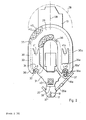
- Fig. 1 is a machine tool 10 with a headstock 11, which is arranged on a telescopically covered height adjustment 12 on a base 13.
- the headstock 11 can also be moved in two coordinate directions perpendicular to its vertical axis 19, but the units required for this are known per se and are not shown in the figures for the sake of clarity.
- a tool 16 which is held by a tool holder 17, is inserted into a spindle head 15.
- the tool holder 17 is in turn held by a holder 18 of a gripping arm 20.
- the tool holder 17 can, for example, be designed such that it can rotate in the holder 18, so that the holder 18 can remain in the working position of the tool holder 17 while the tool 16 is being used on the tool holder 17.
- the gripping arm 20 has a rigid part 21 which is fastened at the bottom to a sleeve 22 which is displaceable on the spindle head 15 in the direction of the vertical axis 19.
- a further rigid part 21a of a further gripper arm 20a is also attached to the sleeve 22.
- a tension spring 23 which acts on one of the rigid parts 21, 21a and also on the headstock 11, the unit consisting of the gripper arms 20, 20a and the sleeve 22 is in the rest position upwards into the working position of a tool holder shown in FIG. 1 17 drawn.
- a first piston-cylinder unit 24 is actuated, the upper end of which is connected to the headstock 11 and the lower end of which is connected to the sleeve 22 or one of the rigid parts 21, 21a.
- the first piston-cylinder unit 24 presses the sleeve 22 downward, so that the tool holder 17 comes out of engagement with the spindle head 15.
- the holders 18 and 18a of the gripping arms 20 and 20a are connected to the rigid parts 21 and 21a via a parallelogram-like linkage 26, 27 and 26a, 27a.
- the linkages 26, 27 and 26a, 27a are actuated by means of second piston-cylinder units 25 and 25a, one end of which engages the rigid part 21 or 21a and the other end of which engages one of the rods 26 and 26a.
- the gripping arms 20, 20a are each set back by approximately 45 °, so that they form an angle of approximately 90 ° to one another.
- the tool holders 17 or 17a therefore travel through a transport path from "rear up” to "front down” or vice versa.
- the parallelogram-like linkage 26, 27 or 26a, 27a By using the parallelogram-like linkage 26, 27 or 26a, 27a, however, the vertical orientation of the tool holder 17 or 17a is maintained, as is their rotational position about their vertical axis.
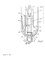
- a magazine 29 is arranged symmetrically to an axis 28, which extends perpendicular to the vertical axis 19 of the headstock 11, which has the shape of a U or a horseshoe in the plan view according to FIG. 2.
- the legs of the magazine 29 are designated 30 and 30a and their ends with 30 'and 30a'.
- V-shaped drive box 31 On the magazine 29 and firmly connected to it there is a V-shaped drive box 31 which is connected in a connecting plane 28 to the headstock 11 and with its legs 41, 41a to the magazine 29.
- the drive box 31 and the magazine 29 preferably form a self-supporting aluminum construction, which is rigidly connected as a cantilever arm in the connecting plane 38 to the headstock 11 and therefore follows all movements of the headstock 11 in the three coordinate axes.
- An outline 39 shows as an example the position of the magazine 29 when the headstock 11 is in its extreme rear position.
- Tool holders 17, 17a can be inserted into the fork-like holder 42 from the front like a drawer.
- a guide in the form of a wall 43 of the magazine 29 is provided which extends in front of the fork opening of the holder 42. This guide is interrupted only in the area of the openings 32 and 32a, as will be explained in more detail below with reference to FIGS. 5 and 6.
- Fig. 1 it can be seen that at 43 'the wall 43 can be continued so far downward and laterally extending that the magazine 29 has a closed shape except for the openings 32 and 32a.
- the tools 16, 16a projecting downward from the magazine 29 in the illustration according to FIG. 1 are protected against flying chips and coolant spraying around, as is the transport chain 33 with the associated drive units.
- a drive motor 40 can be seen which drives a drive wheel designated 45 in Fig. 3.
- the drive wheel 45 is located at the lower tip of a V-shaped endless toothed belt 46 which drives at the ends of the legs of the V drive wheels 47 and 47a, which are connected to the drive axles 34 and 34a in a rotationally rigid manner.
- a tensioning roller 48 can be seen, which can be displaced in the direction of an arrow 49.
- FIG. 4 shows in a sectional view, on the one hand, the at least upwardly closed design of the drive box 31, which, however, apart from the necessary penetrations of the drive axles 34 and 34a, can also be closed at the bottom.
- the tensioning roller 48 is held by an adjusting part 55 which is displaceable in an elongated hole 56 in the direction of the arrow 49 in FIG. 3.
- a fixing screw 57 and an adjusting screw 58 are used to fix or adjust the position.
- the tension in the toothed belt 46 which can of course also be a chain or the like, can be set to the required extent.
- FIG 3 shows a sensor 50 on the drive wheel 47a which, as an incremental sensor, recognizes the respective rotational position of the drive wheel 47a and from this can recognize the position of the tool holders 17, 17a in the holders 42 of the transport chain 33.
- the position of the tool holder 17, 17a can consequently be recognized at any moment by a control device, not shown in the figures, and a desired position can be controlled by a suitable search run.
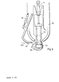
- 5 and 6 illustrate the process for the transfer of tool holders 17, 17a from holders 42 in the magazine 29 to the holder 18 of the gripping arms 20, 20a.
- 60 indicates an outer trajectory, i.e. the locus on which the outer contour of the tool holder 17, 17a moves along when the transport chain 32 moves.
- the movement path 60 is limited by a guide in order to prevent the tool holders 17, 17a from migrating out of the holders 42 of the magazine 29.
- the guide arranged in the movement path 60 ends at the opening 32.
- an arcuate section 61 of a scythe-shaped holding part 62 is provided, which is rotatable about an axis 63.
- a third piston-cylinder unit 64 serves to rotate the holding part 62 about the axis 63.
- the drive box 31 is provided at the end of its free legs 41, 41a with a V-shaped recess 70, at the bottom of which a fourth piston-cylinder unit 71 is rigidly arranged.
- the unit 71 displaces a linkage 72 in a direction parallel to the axis 28, which has a head 73 at its front end.
- the head 73 serves for gripping tool holders 17, 17a, as will be explained in more detail below in relation to FIG. 7.
- the tool holder 17, 17a gripped by the head 73 can be moved between a magazine position 74 and a gripper arm position 75.
- the third piston-cylinder unit 64 is extended and the arcuate section 61 is in the closed position, so that there is a continuous lateral guide for the outer movement path 60.
- the head 73 is in the path of the tool holder 17, 17a, the head 73 being designed such that it does not hinder the passage of the tool holder 17, 17a, as will also be explained in connection with FIG. 7.
- the holder 18 of the gripper arm 20 is located in front of the opening 32 in the immediate vicinity of the arcuate section 61.
- the third piston-cylinder unit 64 is operated, i.e. retracted so that the scythe-shaped holding part 62 is pivoted.
- the arcuate section 61 is pivoted out of the opening 32 on an almost tangential path 65 due to the great length of the holding part 62, so that it does not touch the holder 18 arranged directly in front of it.
- the fourth piston-cylinder unit 71 can be actuated, i.e. are extended so that the head 73 of the tool holder 17, 17a is transferred from the magazine position 74 into the gripper arm position 75.
- Fig. 7 shows the conditions when transferring the tool holder 17 again in detail.
- the tool holder 17 rests in a fork-shaped receptacle 84 of the holder 42, which is offset laterally in such a way that the tool holder 17 can be inserted into the fork-shaped receptacle 84 from the front and pushed out again.
- the head 73 has a front, rigid section 86 and a rear section 87 which can be pivoted about an axis 88, the axis 88 running parallel to the direction of displacement of the head 73.
- the sections 86, 87 are adapted to the inside of the standardized outer contour of the cone of the tool holder 17, there being sufficient play for the contour of the tool holder 17.
- the head 73 can be arranged in the path of the tool holder 17, even if the tool holder 17 is moved through with the transport chain 33. If the tool holder 17 is to be transferred from the magazine 29 into the holder 18 of the gripper arm 20, as previously illustrated with reference to FIGS. 5 and 6, the head 73 moves into the position shown in broken lines in FIG rear section 87 pushes the tool holder 17 into the likewise fork-shaped holder 18 of the gripping arm 20. In this case, the arcuate section 61 drawn in section and drawn through in FIG. 7 is of course pivoted away. Correspondingly, the tool holder 17 can also be transferred from the holder 18 of the gripping arm 20 into the holder 42 of the magazine 29, specifically in that the front section 86 of the head 73 pushes the tool holder 17 into the magazine 29.
- the rear section 87 can be pivoted in a plane perpendicular to the direction of displacement of the head 73.
- FIG. 8 shows that this enables manual loading of the magazine 29.
- the head 73 is brought into the extended position shown in FIG. 8, while at the same time the associated gripping arm 20 is in the spindle position (left half of FIG. 1), that is to say removed, and therefore does not interfere in the region of the opening 32.
- the rear section 87 would hinder the insertion or removal of the tool holder 17, it can now be pivoted in the direction of the arrow shown in FIG. 8 about the axis 88, so that there is now sufficient space around the tool holder 17 in the direction of arrows 90, 91 in the fork-shaped receptacle 84 of the holder 42.
Landscapes
- Engineering & Computer Science (AREA)
- Mechanical Engineering (AREA)
- Automatic Tool Replacement In Machine Tools (AREA)
Claims (14)
Applications Claiming Priority (2)
| Application Number | Priority Date | Filing Date | Title |
|---|---|---|---|
| DE3521009 | 1985-06-12 | ||
| DE19853521009 DE3521009A1 (de) | 1985-06-12 | 1985-06-12 | Werkzeugmaschine |
Publications (3)
| Publication Number | Publication Date |
|---|---|
| EP0205030A2 EP0205030A2 (fr) | 1986-12-17 |
| EP0205030A3 EP0205030A3 (en) | 1987-12-09 |
| EP0205030B1 true EP0205030B1 (fr) | 1990-08-01 |
Family
ID=6273047
Family Applications (1)
| Application Number | Title | Priority Date | Filing Date |
|---|---|---|---|
| EP86107158A Expired - Lifetime EP0205030B1 (fr) | 1985-06-12 | 1986-05-27 | Machine-outil |
Country Status (7)
| Country | Link |
|---|---|
| US (1) | US4683638A (fr) |
| EP (1) | EP0205030B1 (fr) |
| JP (1) | JPH0741498B2 (fr) |
| KR (1) | KR890005087B1 (fr) |
| BR (1) | BR8602836A (fr) |
| DE (1) | DE3521009A1 (fr) |
| ES (1) | ES8704781A1 (fr) |
Families Citing this family (21)
| Publication number | Priority date | Publication date | Assignee | Title |
|---|---|---|---|---|
| DE8526544U1 (fr) * | 1985-09-17 | 1987-04-23 | Chiron-Werke Gmbh, 7200 Tuttlingen, De | |
| DE3627515C1 (de) * | 1986-08-13 | 1987-12-03 | Maho Ag | Werkzeugmagazin fuer insbesondere Fraes- und Bohrmaschinen |
| DE3717016A1 (de) * | 1987-05-21 | 1988-12-08 | Klessmann Ima Norte Maschfab | Werkzeugmaschine mit vertikaler arbeitsspindel und werkzeugwechselvorrichtung |
| DE3732055A1 (de) * | 1987-09-23 | 1989-04-13 | Chiron Werke Gmbh | Werkzeugmaschine |
| DE3831869A1 (de) * | 1988-09-20 | 1990-03-29 | Chiron Werke Gmbh | Werkzeugmaschine |
| US5656223A (en) * | 1991-07-25 | 1997-08-12 | Tokai Kogyo Kabushiki Kaisha | Windshield molding for vehicles and the production method thereof |
| US6095586A (en) * | 1990-10-23 | 2000-08-01 | Tokai Kogyo Kabushiki Kaisha | Automobile windshield molding and the method of producing the same |
| US6196615B1 (en) | 1990-10-23 | 2001-03-06 | Tokai Kogyo Kabushiki Kaisha | Automobile windshield molding and the method of producing the same |
| US5507992A (en) * | 1991-07-25 | 1996-04-16 | Tokai Kogyo Kabushiki Kaisha | Windshield molding for vehicles and the production method thereof |
| DE9303050U1 (fr) * | 1993-03-03 | 1993-04-22 | Festo Kg, 7300 Esslingen, De | |
| JP2814058B2 (ja) * | 1993-09-11 | 1998-10-22 | チロン・ヴェルケ・ゲーエムベーハー・ウント・コー・カーゲー | 工作機械 |
| DE4421385C2 (de) * | 1994-06-18 | 1997-01-23 | Chiron Werke Gmbh | Werkzeugmaschine mit einer Werkzeugwechselvorrichtung |
| DE19830392A1 (de) * | 1998-07-08 | 2000-01-20 | Deckel Maho Seebach Gmbh | Werkzeugwechselvorrichtung für ein Bearbeitungszentrum |
| ITBO20030071A1 (it) * | 2003-02-19 | 2004-08-20 | Jobs Spa | Macchina utensile. |
| US7005359B2 (en) * | 2003-11-17 | 2006-02-28 | Intel Corporation | Bipolar junction transistor with improved extrinsic base region and method of fabrication |
| DE102006028970A1 (de) | 2006-06-19 | 2007-12-20 | Stama Maschinenfabrik Gmbh | Verfahren und Vorrichtung zum Bearbeiten eines Werkstücks, insbesondere zum spanabhebenden Bearbeiten eines metallischen Werkstücks |
| US7520847B1 (en) * | 2008-06-18 | 2009-04-21 | Campro Precision Machinery Co., Ltd. | Tool magazine of automatic tool changer |
| US8294403B2 (en) * | 2009-09-04 | 2012-10-23 | Haas Automation, Inc. | Methods and systems for determining and displaying a time to overload of machine tools |
| JP5949182B2 (ja) * | 2012-06-05 | 2016-07-06 | ブラザー工業株式会社 | 工作機械 |
| EP3351204A1 (fr) * | 2017-01-24 | 2018-07-25 | Martin Huber | Fraiseuse dentaire |
| CN109158936A (zh) * | 2018-11-06 | 2019-01-08 | 浙江理工大学瓯海研究院有限公司 | 一种换刀机构 |
Family Cites Families (17)
| Publication number | Priority date | Publication date | Assignee | Title |
|---|---|---|---|---|
| BE636566A (fr) * | 1962-08-27 | |||
| FR1507373A (fr) * | 1966-11-18 | 1967-12-29 | G S P Guillemin Sergot Pegard | Procédé et mécanisme de changement automatique d'outils sur une machine-outil |
| US3414967A (en) * | 1967-06-30 | 1968-12-10 | Sundstrand Corp | Tool changer |
| GB1349177A (en) * | 1970-09-30 | 1974-03-27 | Rocco Spa S | Automatic tool change apparatus for machine tools |
| US3760490A (en) * | 1971-07-13 | 1973-09-25 | Houdaille Industries Inc | Machine tool having tool changer |
| DE2159552B1 (de) * | 1971-12-01 | 1973-06-14 | Fa A Monforts, 4050 Monchenglad bach | Vorrichtung zum selbsttaetigen beschicken einer automatischen werkzeugmaschine |
| JPS5112476A (ja) * | 1974-07-22 | 1976-01-31 | Toshiba Machine Co Ltd | Jidokogukokansochi |
| JPS5750189Y2 (fr) * | 1977-05-19 | 1982-11-02 | ||
| SU668798A1 (ru) * | 1977-12-26 | 1979-06-25 | Тульский Политехнический Институт | Роторно-конвейерна машина |
| JPS5645734A (en) * | 1979-09-20 | 1981-04-25 | Babcock Hitachi Kk | Dry-type exhaust gas desulfurization process |
| JPS6017655B2 (ja) * | 1980-05-10 | 1985-05-04 | 東芝機械株式会社 | 工具移送ア−ム |
| US4546533A (en) * | 1982-09-07 | 1985-10-15 | Cincinnati Milacron Inc. | Automatic toolchanger system for turning machine |
| DE3376473D1 (en) * | 1982-09-13 | 1988-06-09 | Chiron Werke Gmbh | Machine tool with tool magazine |
| DE3320851A1 (de) * | 1983-06-09 | 1984-12-13 | Chiron-Werke Gmbh, 7200 Tuttlingen | Werkzeugmaschine |
| DE3233934C2 (de) * | 1982-09-13 | 1986-10-23 | Chiron-Werke Gmbh, 7200 Tuttlingen | Werkzeugmaschine mit Werkzeugmagazin |
| DE3410656A1 (de) * | 1984-03-23 | 1985-10-03 | Chiron-Werke Gmbh, 7200 Tuttlingen | Werkzeugmaschine mit einem in mehreren achsen beweglichen spindelstock |
| JPS60249549A (ja) * | 1984-05-25 | 1985-12-10 | Kitamura Kikai Kk | 工具自動交換装置 |
-
1985
- 1985-06-12 DE DE19853521009 patent/DE3521009A1/de active Granted
-
1986
- 1986-05-27 EP EP86107158A patent/EP0205030B1/fr not_active Expired - Lifetime
- 1986-06-10 US US06/872,696 patent/US4683638A/en not_active Expired - Lifetime
- 1986-06-11 BR BR8602836A patent/BR8602836A/pt not_active IP Right Cessation
- 1986-06-11 ES ES555963A patent/ES8704781A1/es not_active Expired
- 1986-06-12 JP JP61137231A patent/JPH0741498B2/ja not_active Expired - Lifetime
- 1986-06-12 KR KR1019860004683A patent/KR890005087B1/ko not_active IP Right Cessation
Also Published As
| Publication number | Publication date |
|---|---|
| US4683638A (en) | 1987-08-04 |
| KR870000135A (ko) | 1987-02-16 |
| ES555963A0 (es) | 1987-04-16 |
| KR890005087B1 (ko) | 1989-12-11 |
| EP0205030A3 (en) | 1987-12-09 |
| JPS6215044A (ja) | 1987-01-23 |
| DE3521009C2 (fr) | 1988-07-07 |
| ES8704781A1 (es) | 1987-04-16 |
| JPH0741498B2 (ja) | 1995-05-10 |
| DE3521009A1 (de) | 1986-12-18 |
| BR8602836A (pt) | 1987-02-10 |
| EP0205030A2 (fr) | 1986-12-17 |
Similar Documents
| Publication | Publication Date | Title |
|---|---|---|
| EP0205030B1 (fr) | Machine-outil | |
| DE2540979C2 (de) | Automatische Werkzeugwechselvorrichtung für eine Vertikal- oder Karusselldrehmaschine | |
| DE3813929C2 (de) | Werkzeugmaschine mit automatischem Werkzeugwechsler | |
| DE2444124C3 (de) | Zusatzeinrichtung zum automatischen Be- und/oder Entladen von Werkzeugmaschinen | |
| DE2739534C2 (de) | Werkzeugwechselvorrichtung | |
| DE3440604C2 (de) | Automatische Werkzeugwechseleinrichtung für Werkzeugmaschinen, insbesondere für Universalbearbeitungszentren | |
| DE4431814A1 (de) | Automatische Werkstoffstangen-Zuführeinrichtung für Werkzeugmaschinen, insbesondere Drehautomaten | |
| DE1552324B2 (de) | Werkzeugmaschine mit automatischem Werkzeugwechsel | |
| DE1477501A1 (de) | Werkzeugmaschine mit Werkzeugwechselvorrichtung | |
| EP0310128B1 (fr) | Système de changement d'outils | |
| DE2512254C2 (de) | Werkzeugwechsler für Horizontal-Bohr-Fräsmaschinen | |
| DE3017613C2 (fr) | ||
| DE2818018C2 (fr) | ||
| DE2710314A1 (de) | Werkzeugmaschine | |
| DE2143780A1 (de) | Werkzeugwechseleinrichtung für Werkzeugmaschinen | |
| EP1511596B1 (fr) | Tour multibroche | |
| DE3829105C2 (fr) | ||
| DE19724635C2 (de) | Werkzeugmaschine mit Werkzeugauswechselvorrichtung | |
| DE19934598A1 (de) | Universal-Fräs- und Bohrmaschine | |
| EP0157950B1 (fr) | Machine-outil avec une poupée mobile suivant plusieurs axes | |
| EP0142749B1 (fr) | Dispositif de changement d'outil pour machine-outil multibroche | |
| EP0255567B1 (fr) | Changeur d'outils pour machine universelle à percer et à fraiser | |
| DE3618959A1 (de) | Werkzeugmaschine zum spanabhebenden bearbeiten von werkstuecken | |
| DE1904093C3 (de) | Werkzeugmaschine mit selbsttätigem Werkzeugwechsel | |
| DE3541563A1 (de) | Werkzeugwechsler |
Legal Events
| Date | Code | Title | Description |
|---|---|---|---|
| PUAI | Public reference made under article 153(3) epc to a published international application that has entered the european phase |
Free format text: ORIGINAL CODE: 0009012 |
|
| AK | Designated contracting states |
Kind code of ref document: A2 Designated state(s): CH FR GB IT LI SE |
|
| PUAL | Search report despatched |
Free format text: ORIGINAL CODE: 0009013 |
|
| AK | Designated contracting states |
Kind code of ref document: A3 Designated state(s): CH FR GB IT LI SE |
|
| 17P | Request for examination filed |
Effective date: 19880225 |
|
| 17Q | First examination report despatched |
Effective date: 19890629 |
|
| GRAA | (expected) grant |
Free format text: ORIGINAL CODE: 0009210 |
|
| AK | Designated contracting states |
Kind code of ref document: B1 Designated state(s): CH FR GB IT LI SE |
|
| ET | Fr: translation filed | ||
| GBT | Gb: translation of ep patent filed (gb section 77(6)(a)/1977) | ||
| ITF | It: translation for a ep patent filed |
Owner name: BUGNION S.P.A. |
|
| ITTA | It: last paid annual fee | ||
| PLBE | No opposition filed within time limit |
Free format text: ORIGINAL CODE: 0009261 |
|
| STAA | Information on the status of an ep patent application or granted ep patent |
Free format text: STATUS: NO OPPOSITION FILED WITHIN TIME LIMIT |
|
| 26N | No opposition filed | ||
| PGFP | Annual fee paid to national office [announced via postgrant information from national office to epo] |
Ref country code: SE Payment date: 19920413 Year of fee payment: 7 |
|
| PGFP | Annual fee paid to national office [announced via postgrant information from national office to epo] |
Ref country code: CH Payment date: 19920703 Year of fee payment: 7 |
|
| PG25 | Lapsed in a contracting state [announced via postgrant information from national office to epo] |
Ref country code: SE Effective date: 19930528 |
|
| PG25 | Lapsed in a contracting state [announced via postgrant information from national office to epo] |
Ref country code: LI Effective date: 19930531 Ref country code: CH Effective date: 19930531 |
|
| REG | Reference to a national code |
Ref country code: CH Ref legal event code: PL |
|
| EUG | Se: european patent has lapsed |
Ref document number: 86107158.7 Effective date: 19931210 |
|
| PGFP | Annual fee paid to national office [announced via postgrant information from national office to epo] |
Ref country code: GB Payment date: 20000410 Year of fee payment: 15 |
|
| PGFP | Annual fee paid to national office [announced via postgrant information from national office to epo] |
Ref country code: FR Payment date: 20000530 Year of fee payment: 15 |
|
| PG25 | Lapsed in a contracting state [announced via postgrant information from national office to epo] |
Ref country code: GB Free format text: LAPSE BECAUSE OF NON-PAYMENT OF DUE FEES Effective date: 20010527 |
|
| GBPC | Gb: european patent ceased through non-payment of renewal fee |
Effective date: 20010527 |
|
| PG25 | Lapsed in a contracting state [announced via postgrant information from national office to epo] |
Ref country code: FR Free format text: LAPSE BECAUSE OF NON-PAYMENT OF DUE FEES Effective date: 20020131 |
|
| PG25 | Lapsed in a contracting state [announced via postgrant information from national office to epo] |
Ref country code: IT Free format text: LAPSE BECAUSE OF NON-PAYMENT OF DUE FEES;WARNING: LAPSES OF ITALIAN PATENTS WITH EFFECTIVE DATE BEFORE 2007 MAY HAVE OCCURRED AT ANY TIME BEFORE 2007. THE CORRECT EFFECTIVE DATE MAY BE DIFFERENT FROM THE ONE RECORDED. Effective date: 20050527 |