EP0205030B1 - Machine tool - Google Patents
Machine tool Download PDFInfo
- Publication number
- EP0205030B1 EP0205030B1 EP86107158A EP86107158A EP0205030B1 EP 0205030 B1 EP0205030 B1 EP 0205030B1 EP 86107158 A EP86107158 A EP 86107158A EP 86107158 A EP86107158 A EP 86107158A EP 0205030 B1 EP0205030 B1 EP 0205030B1
- Authority
- EP
- European Patent Office
- Prior art keywords
- magazine
- machine tool
- tool
- tool according
- spindle
- Prior art date
- Legal status (The legal status is an assumption and is not a legal conclusion. Google has not performed a legal analysis and makes no representation as to the accuracy of the status listed.)
- Expired - Lifetime
Links
Images


Classifications
-
- B—PERFORMING OPERATIONS; TRANSPORTING
- B23—MACHINE TOOLS; METAL-WORKING NOT OTHERWISE PROVIDED FOR
- B23Q—DETAILS, COMPONENTS, OR ACCESSORIES FOR MACHINE TOOLS, e.g. ARRANGEMENTS FOR COPYING OR CONTROLLING; MACHINE TOOLS IN GENERAL CHARACTERISED BY THE CONSTRUCTION OF PARTICULAR DETAILS OR COMPONENTS; COMBINATIONS OR ASSOCIATIONS OF METAL-WORKING MACHINES, NOT DIRECTED TO A PARTICULAR RESULT
- B23Q3/00—Devices holding, supporting, or positioning work or tools, of a kind normally removable from the machine
- B23Q3/155—Arrangements for automatic insertion or removal of tools, e.g. combined with manual handling
- B23Q3/157—Arrangements for automatic insertion or removal of tools, e.g. combined with manual handling of rotary tools
- B23Q3/15713—Arrangements for automatic insertion or removal of tools, e.g. combined with manual handling of rotary tools a transfer device taking a single tool from a storage device and inserting it in a spindle
- B23Q3/1572—Arrangements for automatic insertion or removal of tools, e.g. combined with manual handling of rotary tools a transfer device taking a single tool from a storage device and inserting it in a spindle the storage device comprising rotating or circulating storing means
- B23Q3/15753—Arrangements for automatic insertion or removal of tools, e.g. combined with manual handling of rotary tools a transfer device taking a single tool from a storage device and inserting it in a spindle the storage device comprising rotating or circulating storing means the storage means rotating or circulating in a plane perpendicular to the axis of the spindle
- B23Q3/15766—Arrangements for automatic insertion or removal of tools, e.g. combined with manual handling of rotary tools a transfer device taking a single tool from a storage device and inserting it in a spindle the storage device comprising rotating or circulating storing means the storage means rotating or circulating in a plane perpendicular to the axis of the spindle the axis of the stored tools being arranged perpendicularly to the rotating or circulating plane of the storage means
-
- B—PERFORMING OPERATIONS; TRANSPORTING
- B23—MACHINE TOOLS; METAL-WORKING NOT OTHERWISE PROVIDED FOR
- B23Q—DETAILS, COMPONENTS, OR ACCESSORIES FOR MACHINE TOOLS, e.g. ARRANGEMENTS FOR COPYING OR CONTROLLING; MACHINE TOOLS IN GENERAL CHARACTERISED BY THE CONSTRUCTION OF PARTICULAR DETAILS OR COMPONENTS; COMBINATIONS OR ASSOCIATIONS OF METAL-WORKING MACHINES, NOT DIRECTED TO A PARTICULAR RESULT
- B23Q3/00—Devices holding, supporting, or positioning work or tools, of a kind normally removable from the machine
- B23Q3/155—Arrangements for automatic insertion or removal of tools, e.g. combined with manual handling
- B23Q3/1552—Arrangements for automatic insertion or removal of tools, e.g. combined with manual handling parts of devices for automatically inserting or removing tools
- B23Q3/15526—Storage devices; Drive mechanisms therefor
- B23Q3/15534—Magazines mounted on the spindle
-
- B—PERFORMING OPERATIONS; TRANSPORTING
- B23—MACHINE TOOLS; METAL-WORKING NOT OTHERWISE PROVIDED FOR
- B23Q—DETAILS, COMPONENTS, OR ACCESSORIES FOR MACHINE TOOLS, e.g. ARRANGEMENTS FOR COPYING OR CONTROLLING; MACHINE TOOLS IN GENERAL CHARACTERISED BY THE CONSTRUCTION OF PARTICULAR DETAILS OR COMPONENTS; COMBINATIONS OR ASSOCIATIONS OF METAL-WORKING MACHINES, NOT DIRECTED TO A PARTICULAR RESULT
- B23Q3/00—Devices holding, supporting, or positioning work or tools, of a kind normally removable from the machine
- B23Q3/155—Arrangements for automatic insertion or removal of tools, e.g. combined with manual handling
- B23Q3/157—Arrangements for automatic insertion or removal of tools, e.g. combined with manual handling of rotary tools
- B23Q3/15773—Arrangements for automatic insertion or removal of tools, e.g. combined with manual handling of rotary tools a transfer device taking the tool from a storage device and passing it on to other transfer devices, which insert it in a spindle
-
- Y—GENERAL TAGGING OF NEW TECHNOLOGICAL DEVELOPMENTS; GENERAL TAGGING OF CROSS-SECTIONAL TECHNOLOGIES SPANNING OVER SEVERAL SECTIONS OF THE IPC; TECHNICAL SUBJECTS COVERED BY FORMER USPC CROSS-REFERENCE ART COLLECTIONS [XRACs] AND DIGESTS
- Y10—TECHNICAL SUBJECTS COVERED BY FORMER USPC
- Y10T—TECHNICAL SUBJECTS COVERED BY FORMER US CLASSIFICATION
- Y10T483/00—Tool changing
- Y10T483/17—Tool changing including machine tool or component
- Y10T483/1733—Rotary spindle machine tool [e.g., milling machine, boring, machine, grinding machine, etc.]
- Y10T483/1748—Tool changer between spindle and matrix
- Y10T483/1752—Tool changer between spindle and matrix including tool holder pivotable about axis
- Y10T483/1779—Linearly movable tool holder
-
- Y—GENERAL TAGGING OF NEW TECHNOLOGICAL DEVELOPMENTS; GENERAL TAGGING OF CROSS-SECTIONAL TECHNOLOGIES SPANNING OVER SEVERAL SECTIONS OF THE IPC; TECHNICAL SUBJECTS COVERED BY FORMER USPC CROSS-REFERENCE ART COLLECTIONS [XRACs] AND DIGESTS
- Y10—TECHNICAL SUBJECTS COVERED BY FORMER USPC
- Y10T—TECHNICAL SUBJECTS COVERED BY FORMER US CLASSIFICATION
- Y10T483/00—Tool changing
- Y10T483/18—Tool transfer to or from matrix
- Y10T483/1873—Indexing matrix
Definitions
- the invention relates to a machine tool with a headstock, with at least one tool magazine, in which a plurality of tool holders equipped with tools can be moved along an endless path in a plane perpendicular to the axis of the headstock and with two gripping arms for transporting the tool holder between the removal located on both sides of the headstock - or assembly positions in the tool magazine and a spindle position in a spindle head of the headstock.
- the known machine tool has a headstock that can only be moved in height, under which there is a workpiece table that can be moved in two horizontal coordinates.
- a tool magazine which is rigidly connected to the headstock, is arranged on both sides of the headstock.
- the two tool magazines essentially have the configuration of a carousel with an axis of rotation parallel to the spindle axis and they can be rotated in a horizontal plane in such a way that a freely definable position on the outer circumference of the carousel can be rotated in the vicinity of a spindle head of the headstock.
- Each carousel-like tool magazine has a transport slide which is arranged on a diameter of the circumferential circle defined by the carousel-shaped magazine and with which tools can be moved in a radial direction from the transfer position of the tool magazine into a spindle position or vice versa.
- one of these transport slides is advanced to remove the old tool from the spindle and the other slider is then moved forward to insert the new tool into the spindle.
- the height of the spindle head must be moved to pull the tools into the holder.
- the known machine tool thus has some major disadvantages.
- the configuration of the known machine tool has the result that all the tools contained in the two carousel-like magazines are in the immediate vicinity of the machining position, so that drilling fluids splashing around, but above all drilling chips flying around, can deposit on the tools.
- drilling water will initially settle on a cone of a tool holder and then small drilling chips will stick and this in turn can lead to damage if this tool is inserted into the cone of the spindle head at a later point in time because the cone surfaces lying opposite one another the tool holder are worked with high precision.
- Another major disadvantage of the known machine tool is that the advantages of a quick tool change sought by alternating exchange from the two magazines restrict the sequence of the machining steps. If, for example, a tool A is only present in one of the two magazines, a machining sequence ABCA is not possible because, as a result of the alternate replacement from both magazines, the same tool can only be used at a distance from work steps that is two or an even multiple thereof . If, on the other hand, you want to set the machining sequence explained above, it is necessary to keep the same tool A in stock in both magazines, whereby in extreme cases the advantage achievable with the known machine tool and its two optional tool magazines is completely lost.
- a tool magazine is also known from US-A-4 182 021, in which an endless chain conveyor on an approximately U-shaped path conveys the tools which are gripped at a transfer position to an interchangeable gripper and fed to a spindle of a machine tool.
- an endless chain conveyor on an approximately U-shaped path conveys the tools which are gripped at a transfer position to an interchangeable gripper and fed to a spindle of a machine tool.
- the special geometric shape of the endless path is in no way exploited and by adopting tools at only one position, the shape of the endless path is completely irrelevant in this known tool magazine.
- a machine tool with an automatic tool changing device in which carousel-like tool magazines are also provided on both sides of a spindle, but the axis of rotation of which is perpendicular to the spindle axis.
- two gripping arms are provided, which rotate the tools when moving from the magazine position into the spindle position or vice versa, so that in this known machine tool relatively complex gripping elements are required on the changing arms to prevent the tool holder do not fall out of the gripping elements when changing.
- a tool changing device for machine tools in which behind a headstock with a vertical Spindle axis a tool magazine is arranged at a distance.
- the tool magazine has an oval-shaped endless track with chain conveyor in a horizontal plane.
- Fork-like holders are hinged to the chain, into which the tool holders equipped with tools are inserted.
- Between the headstock and the tool magazine spaced therefrom is a horizontally running transport path, along which a gripping arm which is curved downward can be moved.
- the gripper arm moves back into the area of the tool magazine and takes over a tool holder at a removal position. With this tool holder, the entire gripper arm travels forward along the transport path until it reaches a spindle position and inserts the tool holder into the spindle there.
- the tool changing device has the disadvantage of a considerable space requirement, because behind the actual machine tool a large space is required for the transport device and the separate magazine.
- the relatively long travel of the gripper arm from the magazine to the headstock results in relatively long changeover times, in particular because only one gripper arm is provided, which first removes the old tool from the spindle position, transports it into the magazine, there after switching the magazine remove the new tool, drive it forward and insert it into the spindle.
- a machine tool in which a plurality of gripping arms are arranged in a carousel-like manner around a headstock with a vertical spindle axis.
- Each gripper arm is equipped with a specific tool holder / tool.
- the gripper arms have a parallelogram-like linkage with which the tool holders can be moved from a magazine position radially spaced from the spindle axis into a spindle position.
- all gripping arms are arranged together on a sleeve which encompasses the headstock and can be displaced in height thereon.
- European patent application EP-A-0157 950 (state of the art according to Art. 54 (3) EPC) describes a machine tool with a headstock movable in several axes, in which a tool magazine is also arranged at a distance behind the headstock in a horizontal plane a transport device is provided on both sides of the headstock, with which tool holders can be conveyed from the magazine into the area of the headstock.
- a transport device is provided at the front of the headstock.
- two pendulum-like gripper arms with a horizontal swivel axis are provided at the front of the headstock.
- the left gripper arm can remove a tool holder from the spindle position and feed it to the left transport device, while the right gripper arm simultaneously removes the next tool from the right transport device and inserts it into the spindle position.
- the invention is based on the object of further developing a machine tool of the type mentioned in such a way that an even larger number of different tools can be changed optionally and with minimal changeover times, without this restricting the freely available working space in the vicinity of the spindle head.
- the endless track is U-shaped, that there is a removal or loading position at both ends of the legs of the U and that the spindle head is arranged in front of and below these ends and rigid with the tool magazine in the direction of the axis connected is.
- the design of the magazine in the form of a U or a horseshoe has the advantage that, by appropriately dimensioning the length of the legs of the U, a very large number of tool holders can be stored in the magazine, it also having to be taken into account that the endless path has the shape of the U goes through once inside and once outside. Typically, 32 or significantly more tools can thus be stored in the magazine without the lateral outreach next to the headstock and thus the outward projection becoming too large, as is the case with the two lateral carousel-like tool magazines according to the prior art is.
- the spatial proximity of the removal or assembly position to the headstock is chosen so that on the one hand a minimal tool change time is possible because the small spatial distance of a gripper arm can be bridged, but on the other hand the spacing of the tool magazine towards the rear and upwards relative to the spindle head is so great that contamination of the tools, in particular the cones of the tool holders, must be feared, which are located above the tools and are therefore hardly accessible to splashing drilling water and flying drilling chips.
- the "tapping" of the U-shaped tool magazine at two positions has the advantage that by suitably controlling the transport of the tool holder along the endless path, the tool change time can be significantly reduced.
- the tool magazine can rotate so that the next required tool can be made available at one of the two positions, which now serves as the removal position, and can be removed from one of the two gripping arms.
- This is immediately followed by a search of the magazine, which provides a free space for the workpiece holder now to be removed from the spindle at the other position, which now serves as the loading position.
- the other gripper arm can now remove the "old” tool holder from the spindle and insert it into the empty position, while the other gripper arm is already inserting the "new" tool holder into the spindle.
- the measure of rigidly connecting the tool magazine to the spindle head in the direction of the spindle axis has the advantage that a so-called "variable change plane" can be realized, that is to say that the tool change process is in principle independent of the coordinate position in which the spindle head is located It is time to change the tool because the magazine follows all the movements of the headstock due to the rigid connection.
- the transport between the spindle and magazine positions can therefore take place independently of the respective coordinate position of the spindle head and the paths can therefore be optimized, in particular shortened, independently of the coordinate position.
- the axis of the headstock and the removal or loading positions are arranged symmetrically at the ends of an isosceles triangle and the transport path of the gripping arms runs in the direction of the same triangle sides, the angular position of the tool holder remaining unchanged during transport.
- This measure has the advantage that the symmetry of the arrangement of the transport paths between the spindle on the one hand and the two positions of the tool magazine on the other hand are of the same length, so that the same transport times result.
- the angularly fixed transport of the tool holder also ensures that the driving groove on the tool holder is always in a defined position, so that the insertion of the tool holder into the spindle always brings the driving groove directly into engagement with the sliding block there.
- the gripper arms have a parallelogram-like linkage and are rigidly connected to the headstock in directions perpendicular to the axis, but can be displaced in a direction parallel to the axis.
- This measure has the advantage that the tool holder can be retracted into the spindle with only a single actuating element, for example a piston-cylinder unit, in that the equipping gripper arm holds the tool holder in a position just below the spindle and the gripper arms then as a whole are moved upwards until the tool holder engages in the headstock holder. It is particularly preferred to hold the gripping arms in this upper position overall by means of a tension spring and only to move the gripping arms downward against the force of the tension spring together by means of a piston-cylinder unit in order to unclamp the tool holder.
- a single actuating element for example a piston-cylinder unit
- a transport chain is guided along the endless path, on which holders for the tool holders are articulated, and two synchronously driven drive wheels are arranged for the transport chain at the ends of the U.
- This measure has the advantage that the transport of the tool holder takes place completely free of play because, due to the synchronous drive at two points of the endless path at which the removal or the loading takes place, play due to possible lengthening of the chain is excluded.
- the tools are therefore in the correct position at the removal points, which was preferably determined by an incremental sensor on a chain shaft.
- the drive wheels are driven by means of a V-shaped endless belt, preferably a toothed belt or a chain, the drive wheels being located on the free ends of the legs of the V and a drive wheel and a roller spaced therefrom are at their intersection.
- This measure has the advantage that the desired synchronous running of the two drive wheels can be ensured in a particularly simple manner with only one drive motor.
- the roller is designed as a tensioning roller for the belt or chain that can be displaced in the direction of the drive wheel.
- This measure has the advantage that the belt or chain tension can be adjusted in a particularly simple manner if this should become necessary.
- the drive wheels, the drive wheel, the roller and the belt are located in a V-shaped drive box.
- This measure has the advantage that the drive belt or the chain run protected inside the hollow body formed by the drive box.
- drive box with its free legs carries the magazine on its free legs and is attached to the headstock with the tip of the V, drive box and magazine preferably are designed as a self-supporting aluminum construction.
- This measure has the particular advantage that a particularly light design is possible, which is of particular importance when moving the headstock in several coordinate directions, because the headstock must "drag" the magazine and the drive device.
- the tool holders are held on the U-shaped endless track of the magazine in fork-like holders, the open side of which points away from the U, a magazine-fixed guide, preferably a wall of the magazine, runs along the endless track in front of the open page and the The guide has an opening at each of the removal or loading positions.
- This measure has the advantage that the removal or loading of tool holders can be carried out particularly easily because, due to the drawer-like function of the fork-like holders, the tool holders can simply be inserted from the front or removed from the front. Because of the magazine-fixed guidance, it is impossible for the tool holders to slide out of the fork-like holders under the influence of centrifugal force at high throughput through the curves of the U. Openings are only provided at the positions for removal and loading to enable these operations.
- the opening is spanned by an arcuate section which forms the upper end of a scythe-shaped holding part which can be pivoted at its lower end.
- This measure has the advantage that the opening at a removal position can be closed again immediately after removal of the tool holder and a search run of the magazine can follow, which in the manner already described serves to find an empty space for the tool holder to be removed from the spindle .
- the design of the holding part in the form of a scythe with an axis of rotation at the lower end has the advantage that the upper, arc-shaped section can be pivoted away practically tangentially from the removal or loading position if the lower end is of sufficient length. This has the advantage that a holder of the gripping arm can already be located directly in front of the removal or loading position, without the risk of a collision with the curved section pivoting away.
- a magazine-fixed slide arrangement is arranged perpendicular to the endless web at the removal or loading positions, with which tool holders can be moved from fork-like holders of the magazine that are open on one side into or out of a likewise fork-like holder of the gripping arm in the magazine position.
- This relatively quick to operate slide arrangement has the advantage that the tool holder is transferred quickly from the magazine into the gripping arm or vice versa, so that the tool changing times can be kept short.
- the slide arrangement has a head which is provided with two sections arranged one behind the other in the direction of displacement, which hold the tool holder to be displaced in a positive manner in both displacement directions.
- the head can remain in the path of travel of the tool holder during the passage of the magazine, so that it is not initially moved out separately into this position during a transfer process got to.
- this design of the head has the advantage that transfer operations can be carried out in both directions, namely into and out of the magazine.
- the section of the head pointing away from the gripping arm can be pivoted about an axis parallel to the direction of displacement.
- This measure has the advantage that when the head is extended from the magazine while the rear section is pivoted away, the magazine can be loaded or emptied by hand because access to the fork-like receptacles of the magazine is then free.
- an embodiment of the invention is preferred, in which the magazine is surrounded by a wall which is closed on all sides with the exception of openings at the removal and loading positions.
- This measure has the advantage that the tools and tool holders in the magazine are completely protected from chips and coolant splashes, as are the transport and drive units arranged in the magazine.
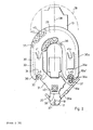
- Fig. 1 is a machine tool 10 with a headstock 11, which is arranged on a telescopically covered height adjustment 12 on a base 13.
- the headstock 11 can also be moved in two coordinate directions perpendicular to its vertical axis 19, but the units required for this are known per se and are not shown in the figures for the sake of clarity.
- a tool 16 which is held by a tool holder 17, is inserted into a spindle head 15.
- the tool holder 17 is in turn held by a holder 18 of a gripping arm 20.
- the tool holder 17 can, for example, be designed such that it can rotate in the holder 18, so that the holder 18 can remain in the working position of the tool holder 17 while the tool 16 is being used on the tool holder 17.
- the gripping arm 20 has a rigid part 21 which is fastened at the bottom to a sleeve 22 which is displaceable on the spindle head 15 in the direction of the vertical axis 19.
- a further rigid part 21a of a further gripper arm 20a is also attached to the sleeve 22.
- a tension spring 23 which acts on one of the rigid parts 21, 21a and also on the headstock 11, the unit consisting of the gripper arms 20, 20a and the sleeve 22 is in the rest position upwards into the working position of a tool holder shown in FIG. 1 17 drawn.
- a first piston-cylinder unit 24 is actuated, the upper end of which is connected to the headstock 11 and the lower end of which is connected to the sleeve 22 or one of the rigid parts 21, 21a.
- the first piston-cylinder unit 24 presses the sleeve 22 downward, so that the tool holder 17 comes out of engagement with the spindle head 15.
- the holders 18 and 18a of the gripping arms 20 and 20a are connected to the rigid parts 21 and 21a via a parallelogram-like linkage 26, 27 and 26a, 27a.
- the linkages 26, 27 and 26a, 27a are actuated by means of second piston-cylinder units 25 and 25a, one end of which engages the rigid part 21 or 21a and the other end of which engages one of the rods 26 and 26a.
- the gripping arms 20, 20a are each set back by approximately 45 °, so that they form an angle of approximately 90 ° to one another.
- the tool holders 17 or 17a therefore travel through a transport path from "rear up” to "front down” or vice versa.
- the parallelogram-like linkage 26, 27 or 26a, 27a By using the parallelogram-like linkage 26, 27 or 26a, 27a, however, the vertical orientation of the tool holder 17 or 17a is maintained, as is their rotational position about their vertical axis.
- a magazine 29 is arranged symmetrically to an axis 28, which extends perpendicular to the vertical axis 19 of the headstock 11, which has the shape of a U or a horseshoe in the plan view according to FIG. 2.
- the legs of the magazine 29 are designated 30 and 30a and their ends with 30 'and 30a'.
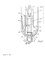
- V-shaped drive box 31 On the magazine 29 and firmly connected to it there is a V-shaped drive box 31 which is connected in a connecting plane 28 to the headstock 11 and with its legs 41, 41a to the magazine 29.
- the drive box 31 and the magazine 29 preferably form a self-supporting aluminum construction, which is rigidly connected as a cantilever arm in the connecting plane 38 to the headstock 11 and therefore follows all movements of the headstock 11 in the three coordinate axes.
- An outline 39 shows as an example the position of the magazine 29 when the headstock 11 is in its extreme rear position.
- Tool holders 17, 17a can be inserted into the fork-like holder 42 from the front like a drawer.
- a guide in the form of a wall 43 of the magazine 29 is provided which extends in front of the fork opening of the holder 42. This guide is interrupted only in the area of the openings 32 and 32a, as will be explained in more detail below with reference to FIGS. 5 and 6.
- Fig. 1 it can be seen that at 43 'the wall 43 can be continued so far downward and laterally extending that the magazine 29 has a closed shape except for the openings 32 and 32a.
- the tools 16, 16a projecting downward from the magazine 29 in the illustration according to FIG. 1 are protected against flying chips and coolant spraying around, as is the transport chain 33 with the associated drive units.
- a drive motor 40 can be seen which drives a drive wheel designated 45 in Fig. 3.
- the drive wheel 45 is located at the lower tip of a V-shaped endless toothed belt 46 which drives at the ends of the legs of the V drive wheels 47 and 47a, which are connected to the drive axles 34 and 34a in a rotationally rigid manner.
- a tensioning roller 48 can be seen, which can be displaced in the direction of an arrow 49.
- FIG. 4 shows in a sectional view, on the one hand, the at least upwardly closed design of the drive box 31, which, however, apart from the necessary penetrations of the drive axles 34 and 34a, can also be closed at the bottom.
- the tensioning roller 48 is held by an adjusting part 55 which is displaceable in an elongated hole 56 in the direction of the arrow 49 in FIG. 3.
- a fixing screw 57 and an adjusting screw 58 are used to fix or adjust the position.
- the tension in the toothed belt 46 which can of course also be a chain or the like, can be set to the required extent.
- FIG 3 shows a sensor 50 on the drive wheel 47a which, as an incremental sensor, recognizes the respective rotational position of the drive wheel 47a and from this can recognize the position of the tool holders 17, 17a in the holders 42 of the transport chain 33.
- the position of the tool holder 17, 17a can consequently be recognized at any moment by a control device, not shown in the figures, and a desired position can be controlled by a suitable search run.
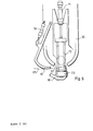
- 5 and 6 illustrate the process for the transfer of tool holders 17, 17a from holders 42 in the magazine 29 to the holder 18 of the gripping arms 20, 20a.
- 60 indicates an outer trajectory, i.e. the locus on which the outer contour of the tool holder 17, 17a moves along when the transport chain 32 moves.
- the movement path 60 is limited by a guide in order to prevent the tool holders 17, 17a from migrating out of the holders 42 of the magazine 29.
- the guide arranged in the movement path 60 ends at the opening 32.
- an arcuate section 61 of a scythe-shaped holding part 62 is provided, which is rotatable about an axis 63.
- a third piston-cylinder unit 64 serves to rotate the holding part 62 about the axis 63.
- the drive box 31 is provided at the end of its free legs 41, 41a with a V-shaped recess 70, at the bottom of which a fourth piston-cylinder unit 71 is rigidly arranged.
- the unit 71 displaces a linkage 72 in a direction parallel to the axis 28, which has a head 73 at its front end.
- the head 73 serves for gripping tool holders 17, 17a, as will be explained in more detail below in relation to FIG. 7.
- the tool holder 17, 17a gripped by the head 73 can be moved between a magazine position 74 and a gripper arm position 75.
- the third piston-cylinder unit 64 is extended and the arcuate section 61 is in the closed position, so that there is a continuous lateral guide for the outer movement path 60.
- the head 73 is in the path of the tool holder 17, 17a, the head 73 being designed such that it does not hinder the passage of the tool holder 17, 17a, as will also be explained in connection with FIG. 7.
- the holder 18 of the gripper arm 20 is located in front of the opening 32 in the immediate vicinity of the arcuate section 61.
- the third piston-cylinder unit 64 is operated, i.e. retracted so that the scythe-shaped holding part 62 is pivoted.
- the arcuate section 61 is pivoted out of the opening 32 on an almost tangential path 65 due to the great length of the holding part 62, so that it does not touch the holder 18 arranged directly in front of it.
- the fourth piston-cylinder unit 71 can be actuated, i.e. are extended so that the head 73 of the tool holder 17, 17a is transferred from the magazine position 74 into the gripper arm position 75.
- Fig. 7 shows the conditions when transferring the tool holder 17 again in detail.
- the tool holder 17 rests in a fork-shaped receptacle 84 of the holder 42, which is offset laterally in such a way that the tool holder 17 can be inserted into the fork-shaped receptacle 84 from the front and pushed out again.
- the head 73 has a front, rigid section 86 and a rear section 87 which can be pivoted about an axis 88, the axis 88 running parallel to the direction of displacement of the head 73.
- the sections 86, 87 are adapted to the inside of the standardized outer contour of the cone of the tool holder 17, there being sufficient play for the contour of the tool holder 17.
- the head 73 can be arranged in the path of the tool holder 17, even if the tool holder 17 is moved through with the transport chain 33. If the tool holder 17 is to be transferred from the magazine 29 into the holder 18 of the gripper arm 20, as previously illustrated with reference to FIGS. 5 and 6, the head 73 moves into the position shown in broken lines in FIG rear section 87 pushes the tool holder 17 into the likewise fork-shaped holder 18 of the gripping arm 20. In this case, the arcuate section 61 drawn in section and drawn through in FIG. 7 is of course pivoted away. Correspondingly, the tool holder 17 can also be transferred from the holder 18 of the gripping arm 20 into the holder 42 of the magazine 29, specifically in that the front section 86 of the head 73 pushes the tool holder 17 into the magazine 29.
- the rear section 87 can be pivoted in a plane perpendicular to the direction of displacement of the head 73.
- FIG. 8 shows that this enables manual loading of the magazine 29.
- the head 73 is brought into the extended position shown in FIG. 8, while at the same time the associated gripping arm 20 is in the spindle position (left half of FIG. 1), that is to say removed, and therefore does not interfere in the region of the opening 32.
- the rear section 87 would hinder the insertion or removal of the tool holder 17, it can now be pivoted in the direction of the arrow shown in FIG. 8 about the axis 88, so that there is now sufficient space around the tool holder 17 in the direction of arrows 90, 91 in the fork-shaped receptacle 84 of the holder 42.
Landscapes
- Engineering & Computer Science (AREA)
- Mechanical Engineering (AREA)
- Automatic Tool Replacement In Machine Tools (AREA)
Description
Die Erfindung betrifft eine Werkzeugmaschine mit einem Spindelstock, mit mindestens einem Werkzeugmagazin, in dem eine Mehrzahl von mit Werkzeugen bestückten Werkzeughaltern entlang einer Endlosbahn in einer Ebene senkrecht zur Achse des Spindelstocks verfahrbar ist und mit zwei Greifarmen zum Transportieren der Werkzeughalter zwischen beidseits des Spindelstocks befindlichen Entnahme- bzw. Bestückungspositionen im Werkzeugmagzin und einer Spindelposition in einem Spindelkopf des Spindelstocks.The invention relates to a machine tool with a headstock, with at least one tool magazine, in which a plurality of tool holders equipped with tools can be moved along an endless path in a plane perpendicular to the axis of the headstock and with two gripping arms for transporting the tool holder between the removal located on both sides of the headstock - or assembly positions in the tool magazine and a spindle position in a spindle head of the headstock.
Eine derartige Werkzeugmaschine ist aus der US-A-3 200 492 bekannt.Such a machine tool is known from US-A-3,200,492.
Die bekannte Werkzeugmaschine weist einen nur in der Höhe verfahrbaren Spindelstock auf, unter dem sich ein in zwei Horizontalkoordinaten verfahrbarer Werkstücktisch befindet. Auf beiden Seiten des Spindestocks ist je ein Werkzeugmagazin angeordnet, das mit dem Spindelstock starr verbunden ist. Die beiden Werkzeugmagazine haben im wesentlichen die Konfiguration eines Karussells mit zur Spindelachse paralleler Drehachse und sie sind so in einer Horizontalebene verdrehbar, daß eine frei vorgebbare position am Außenumfang des Karussells in die Nähe eines Spindelkopfs des Spindelstocks gedreht werden kann. Jedes karussellartige Werkzeugmagazin weist einen Transportschieber auf, der auf einem Durchmesser des von dem karussellförmigen Magazin definierten Umfangskreises angeordnet ist und mit dem Werkzeuge in einer radialen Richtung aus der Übergabeposition des Werkzeugmagazins in eine Spindelposition bzw. umgekehrt verfahren werden können. Zum Werkzeugwechsel wird einer dieser Transportschieber vorgefahren, um das alte Werkzeug aus der Spindel zu entnehmen und nachfolgend wird der jeweils andere Schieber vorgefahren, um das neue Werkzeug in die Spindel einzusetzen. Zum Einziehen der Werkzeuge in die Aufnahme des Spindelkopfes muß dieser in der Höhe verfahren werden. Wenn das neue Werkzeug in die Aufnahme des Spindelkopfs eingesetzt worden ist, fährt dieser ein kurzes Stück nach unten, bis das neue Werkzeug in Eingriff mit dem Werkstück gelangt.The known machine tool has a headstock that can only be moved in height, under which there is a workpiece table that can be moved in two horizontal coordinates. A tool magazine, which is rigidly connected to the headstock, is arranged on both sides of the headstock. The two tool magazines essentially have the configuration of a carousel with an axis of rotation parallel to the spindle axis and they can be rotated in a horizontal plane in such a way that a freely definable position on the outer circumference of the carousel can be rotated in the vicinity of a spindle head of the headstock. Each carousel-like tool magazine has a transport slide which is arranged on a diameter of the circumferential circle defined by the carousel-shaped magazine and with which tools can be moved in a radial direction from the transfer position of the tool magazine into a spindle position or vice versa. To change the tool, one of these transport slides is advanced to remove the old tool from the spindle and the other slider is then moved forward to insert the new tool into the spindle. The height of the spindle head must be moved to pull the tools into the holder. When the new tool has been inserted into the spindle head holder, it moves down a short distance until the new tool comes into engagement with the workpiece.
Die bekannte Werkzeugmaschine hat damit einige wesentliche Nachteile. Zum einen ist von Nachteil, daß durch die beiden karussellartigen Magazine in unmittelbarer Nähe des Spindelkopfes ein erheblicher Raumbedarf dort besteht, wo gerade genügend Arbeitsraum zur Verfugung stehen sollte, um auch große und sperrige Werkstücke bearbeiten zu können. Zum anderen hat die Konfiguration der bekannten Werkzeugmaschine zur Folge, daß sich alle in den beiden karussellartigen Magazinen enthaltenen Werkzeuge in unmittelbarer Nähe der Bearbeitungsposition befinden, so daß sich herumspritzende Bohrflüssigkeiten, vor allem aber auch herumfliegende Bohrspäne, auf den Werkzeugen absetzen können. Es ist daher durchaus möglich, daß sich auf einem Kegel eines Werkzeughalters zunächst Bohrwasser absetzt und dann kleine Bohrspäne kleben bleiben und dies kann wiederum zu Beschädigungen führen, wenn dieses Werkzeug zu einem späteren Zeitpunkt in den Aufnahmekonus des Spindelkopfes eingesetzt wird, weil die einander gegenüberliegenden Kegelflächen der Werkzeugaufnahme hochpräzise gearbeitet sind.The known machine tool thus has some major disadvantages. On the one hand, it is disadvantageous that the two carousel-like magazines in the immediate vicinity of the spindle head require a considerable amount of space where there is just enough work space available to be able to machine large and bulky workpieces. On the other hand, the configuration of the known machine tool has the result that all the tools contained in the two carousel-like magazines are in the immediate vicinity of the machining position, so that drilling fluids splashing around, but above all drilling chips flying around, can deposit on the tools. It is therefore quite possible that drilling water will initially settle on a cone of a tool holder and then small drilling chips will stick and this in turn can lead to damage if this tool is inserted into the cone of the spindle head at a later point in time because the cone surfaces lying opposite one another the tool holder are worked with high precision.
Ein weiterer wesentlicher Nachteil der bekannten Werkzeugmaschine liegt darin, daß die damit erstrebten Vorteile eines schnellen Werkzeugwechsels durch wechselweises Austauschen aus den beiden Magazinen die Reihenfolge der Bearbeitungsschritte einschränken. Wenn beispielsweise ein Werkzeug A nur in einem der beiden Magazine vorhanden ist, ist eine Bearbeitungsfolge-A-B-C-A nicht möglich, weil infolge des alternativen Einwechselns aus beiden Magazinen dasselbe Werkzeug nur in einem Abstand von Arbeitsschritten eingesetzt werden kann, der zwei oder ein geradzahliges Vielfaches davon beträgt. Will man hingegen die oben erläuterte Bearbeitungsfolge einstellen, ist es erforderlich, das gleiche Werkzeug A in beiden Magazinen vorrätig zu halten, wodurch im Extremfall der mit der bekannten Werkzeugmaschine und deren zwei wahlfreien Werkzeugmagazinen erreichbarer Vorteil vollkommen verloren geht.Another major disadvantage of the known machine tool is that the advantages of a quick tool change sought by alternating exchange from the two magazines restrict the sequence of the machining steps. If, for example, a tool A is only present in one of the two magazines, a machining sequence ABCA is not possible because, as a result of the alternate replacement from both magazines, the same tool can only be used at a distance from work steps that is two or an even multiple thereof . If, on the other hand, you want to set the machining sequence explained above, it is necessary to keep the same tool A in stock in both magazines, whereby in extreme cases the advantage achievable with the known machine tool and its two optional tool magazines is completely lost.
Schließlich ist bei der bekannten Werkzeugmaschine noch von Nachteil, daß durch die eindimensionale Bewegung der Transportschieber die Spindel zum Werkzeugwechsel in senkrechter Richtung verfahren werden muß, was eine Verlängerung der Werkzeugwechselzeiten zur Folge hat.Finally, it is a disadvantage of the known machine tool that the spindle has to be moved in the vertical direction for the tool change due to the one-dimensional movement of the transport slide, which results in an extension of the tool change times.
Aus der US-A-4 182 021 ist noch ein Werkzeugmagazin bekannt, bei dem ein endloser Kettenförderer auf einer näherungsweise U-förmigen Bahn die Werkzeuge fördert, die an einer Übergabeposition zu einem Wechselgreifer ergriffen und einer Spindel einer Werkzeugmaschine zugeführt werden. Allerdings ist bei diesem bekannten Magazin in keiner Weise die besondere geometrische Form der Endlosbahn ausgenutzt und durch die Übernahme von Werkzeugen an nur einer einzigen Position ist die Form der Endlosbahn bei diesem bekannten Werkzeugmagazin völlig ohne Bedeutung.A tool magazine is also known from US-A-4 182 021, in which an endless chain conveyor on an approximately U-shaped path conveys the tools which are gripped at a transfer position to an interchangeable gripper and fed to a spindle of a machine tool. However, in this known magazine the special geometric shape of the endless path is in no way exploited and by adopting tools at only one position, the shape of the endless path is completely irrelevant in this known tool magazine.
Aus der DE-A-21 63 499 ist eine Werkzeugmaschine mit automatischer Werkzeug-Wechselvorrichtung bekannt, bei der ebenfalls zu beiden Seiten einer Spindel karussellartige Werkzeugmagazine vorgesehen sind, deren Drehachse jedoch senkrecht zur Spindelachse steht. Zum Einwechseln der Werkzeughalter sind zwei Greifarme vorgesehen, die die Werkzeuge beim Verfahren von der Magazinstellung in die Spindelstellung bzw. umgekehrt um 90° drehen, so daß bei dieser bekannten Werkzeugmaschine relativ aufwendige Greifelemente an den Wechselarmen erforderlich sind, um zu verhindern, daß die Werkzeughalter beim Wechsel nicht aus den Greifelementen herausfallen.From DE-A-21 63 499 a machine tool with an automatic tool changing device is known, in which carousel-like tool magazines are also provided on both sides of a spindle, but the axis of rotation of which is perpendicular to the spindle axis. To change the tool holder, two gripping arms are provided, which rotate the tools when moving from the magazine position into the spindle position or vice versa, so that in this known machine tool relatively complex gripping elements are required on the changing arms to prevent the tool holder do not fall out of the gripping elements when changing.
Aus der DE-A-17 52 605 ist eine Werkzeugwechselvorrichtung für Werkzeugmaschinen bekannt, bei der hinter einem Spindelstock mit senkrechter Spindelachse im Abstand ein Werkzeugmagazin angeordnet ist. Das Werkzeugmagazin weist in einer horizontalen Ebene eine ovalförmige Endlosbahn mit Kettenförderung auf. An der Kette sind gabelartige Halter angelenkt, in die die mit Werkzeugen bestückten Werkzeughalter eingesetzt sind. Zwischen dem Spindelstock und dem davon beabstandeten Werkzeugmagazin befindet sich eine horizontal verlaufende Transportbahn, entlang der ein nach unten gekrümmt verlaufender Greifarm verfahrbar ist. Der Greifarm fährt zum Entnehmen eines Werkzeuges aus dem Magazin nach hinten in den Bereich des Werkzeugmagazins und übernimmt an einer Entnahmeposition einen Werkzeughalter. Mit diesem Werkzeughalter fährt der gesamte Greifarm entlang der Transportbahn nach vorne, bis er in eine Spindelposition gelangt und dort den Werkzeughalter in die Spindel einsetzt.From DE-A-17 52 605 a tool changing device for machine tools is known in which behind a headstock with a vertical Spindle axis a tool magazine is arranged at a distance. The tool magazine has an oval-shaped endless track with chain conveyor in a horizontal plane. Fork-like holders are hinged to the chain, into which the tool holders equipped with tools are inserted. Between the headstock and the tool magazine spaced therefrom is a horizontally running transport path, along which a gripping arm which is curved downward can be moved. To remove a tool from the magazine, the gripper arm moves back into the area of the tool magazine and takes over a tool holder at a removal position. With this tool holder, the entire gripper arm travels forward along the transport path until it reaches a spindle position and inserts the tool holder into the spindle there.
Die Werkzeugwechselvorrichtung gemäß DE-A-17 52 605 hat den Nachteil eines beträchtlichen Raumbedarfes, weil hinter der eigentlichen Werkzeugmaschine ein großer Raum für die Transporteinrichtung und das getrennt stehende Magazin erforderlich ist. Außerdem ergeben sich durch den relativ langen Fahrweg des Greifarmes vom Magazin zum Spindelstock verhältnismäßig lange Umrüstzeiten, insbesondere auch deswegen, weil nur ein einziger Greifarm vorgesehen ist, der zunächst das alte Werkzeug aus der Spindelposition entnehmen, in das Magazin transportieren, dort nach Weiterschalten des Magazins das neue Werkzeug entnehmen, vorfahren und in die Spindel einsetzen muß.The tool changing device according to DE-A-17 52 605 has the disadvantage of a considerable space requirement, because behind the actual machine tool a large space is required for the transport device and the separate magazine. In addition, the relatively long travel of the gripper arm from the magazine to the headstock results in relatively long changeover times, in particular because only one gripper arm is provided, which first removes the old tool from the spindle position, transports it into the magazine, there after switching the magazine remove the new tool, drive it forward and insert it into the spindle.
Aus der DE-A-33 20 851 ist eine Werkzeugmaschine bekannt, bei der um einen Spindelstock mit senkrechter Spindelachse herum eine Vielzahl von Greifarmen karussellartig angeordnet ist. Jeder Greifarm ist mit einem bestimmten Werkzeughalter/Werkzeug bestückt. Die Greifarmeweisen ein parallelogrammartiges Gestänge auf, mit dem die Werkzeughalter aus einer von der Spindelachse radial beabstandeten Magazinposition in eine Spindelposition verfahren werden können. Außerdem sind alle Greifarme gemeinsam an einer Hülse angeordnet, die den Spindelstock umfaßt und auf diesem in der Höhe verschiebbar ist.From DE-A-33 20 851 a machine tool is known in which a plurality of gripping arms are arranged in a carousel-like manner around a headstock with a vertical spindle axis. Each gripper arm is equipped with a specific tool holder / tool. The gripper arms have a parallelogram-like linkage with which the tool holders can be moved from a magazine position radially spaced from the spindle axis into a spindle position. In addition, all gripping arms are arranged together on a sleeve which encompasses the headstock and can be displaced in height thereon.
Zwar sind bei der Werkzeugmaschine gemäß DE-A-33 20 851 die Werkzeugwechselzeiten erheblich kürzer, weil sämtliche Werkzeughalter sich in unmittelbarer Nähe der Spindel, nämlich karussellartig um diese herum, befinden, der konstruktive Aufwand ist jedoch beträchtlich, weil für jeden Werkzeughalter ein eigener Greifarm mit Betätigungsmechanik vorgesehen sein muß. Außerdem ist durch diese Art der Magazinierung der Anzahl der Werkzeuge eine bestimmte Grenze gesetzt, so daß nur eine ebenfalls begrenzte Zahl von Bearbeitungsschritten ohne Umrüsten der Werkzeuge im Magazin ausgeführt werden kann.Although in the machine tool according to DE-A-33 20 851 the tool changing times are considerably shorter because all tool holders are in the immediate vicinity of the spindle, namely around it like a carousel, the design effort is considerable because each tool holder has its own gripping arm must be provided with actuating mechanism. In addition, this type of magazining places a certain limit on the number of tools, so that only a likewise limited number of machining steps can be carried out in the magazine without retooling the tools.
In der europäischen Patentanmeldung EP-A-0157 950 (Stand der Technik gemäß Art. 54(3) EPÜ) ist eine Werkzeugmaschine mit einem in mehreren Achen beweglichen Spindelstock beschrieben, bei der ein Werkzeugmagazin ebenfalls im Abstand hinter dem Spindelstock in einer horizontalen Ebene angeordnet ist, wobei an beiden Seiten des Spindelstocks je eine Transporteinrichtung vorgesehen ist, mit der Werkzeughalter vom Magazin in den Bereich des Spindelstocks gefördert werden können. An der Vorderseite des Spindelstocks sind zwei pendelartige Greifarme mit horizontaler Schwenkachse vorgesehen. So kann beispielsweise der linke Greifarm einen Werkzeughalter aus der Spindelposition entnehmen und der linken Transporteinrichtung zuführen, während simmultan der rechte Greifarm aus der rechten Transportvorrichtung das nächste Werkzeug entnimmt und in die Spindelposition einsetzt.European patent application EP-A-0157 950 (state of the art according to Art. 54 (3) EPC) describes a machine tool with a headstock movable in several axes, in which a tool magazine is also arranged at a distance behind the headstock in a horizontal plane a transport device is provided on both sides of the headstock, with which tool holders can be conveyed from the magazine into the area of the headstock. At the front of the headstock two pendulum-like gripper arms with a horizontal swivel axis are provided. For example, the left gripper arm can remove a tool holder from the spindle position and feed it to the left transport device, while the right gripper arm simultaneously removes the next tool from the right transport device and inserts it into the spindle position.
Der Erfindung liegt demgegenüber die Aufgabe zugrunde, eine Werkzeugmaschine der eingangs genannten Art dahingehend weiterzubilden, daß eine noch größere Anzahl unterschiedlicher Werkzeuge wahlfrei und bei minimalen Umrüstzeiten eingewechselt werden kann, ohne daß dies den frei verfügbaren Arbeitsraum in der Nähe des Spindelkopfs einschränkt.The invention is based on the object of further developing a machine tool of the type mentioned in such a way that an even larger number of different tools can be changed optionally and with minimal changeover times, without this restricting the freely available working space in the vicinity of the spindle head.
Diese Aufgabe wird erfindungsgemäß dadurch gelöst, daß die Endlosbahn U-förmig verläuft, daß sich an beiden Enden der Schenkel des U eine Entnahme- bzw. Bestückungsposition befindet und daß der Spindelkopf vor und unterhalb dieser Enden angeordnet und mit dem Werkzeugmagazin in Richtung der Achse starr verbunden ist.This object is achieved in that the endless track is U-shaped, that there is a removal or loading position at both ends of the legs of the U and that the spindle head is arranged in front of and below these ends and rigid with the tool magazine in the direction of the axis connected is.
Die der Erfindung zugrunde liegende Aufgabe wird damit vollkommen gelöst.The object underlying the invention is thus completely achieved.
Die Gestaltung des Magazins in Form eines U bzw. eines Hufeisens hat nämlich den Vorteil, daß durch geeignete Dimensionierung der Länge der Schenkel des U eine sehr große Zahl von Werkzeughaltern im Magazin gespeichert werden kann, wobei weiter zu berücksichtigen ist, daß die Endlosbahn die Form des U einmal innen und einmal außen durchläuft. Es können somit typischerweise 32 oder auch wesentlich mehr Werkzeuge im Magazin gespeichert werden, ohne daß hierdurch die seitliche Ausladung neben dem Spindelstock und damit auch die Ausladung nach vorne zu groß wird, wie dies bei den beiden seitlichen karussellartigen Werkzeugmagazinen nach dem Stand der Technik der Fall ist. Die räumliche Nähe der Entnahme- bzw. Bestükkungsposition zum Spindelstock ist dabei so gewählt, daß einerseits eine minimale Werkzeugwechselzeit möglich ist, weil die geringe räumliche Entfernung eines Greifarmes überbrückt werden kann, andererseits ist aber die Beabstandung des Werkzeugmagazins nach hinten und oben gegenüber dem Spindelkopf so groß, daß eine Verschmutzung der Werkzeuge, insbesondere der Konusse der Werkzeughalter nicht befürchtet werden muß, die sich oberhalb der Werkzeuge befinden und somit für herumspritzendes Bohrwasser und herumfliegende Bohrspäne kaum zugänglich sind.The design of the magazine in the form of a U or a horseshoe has the advantage that, by appropriately dimensioning the length of the legs of the U, a very large number of tool holders can be stored in the magazine, it also having to be taken into account that the endless path has the shape of the U goes through once inside and once outside. Typically, 32 or significantly more tools can thus be stored in the magazine without the lateral outreach next to the headstock and thus the outward projection becoming too large, as is the case with the two lateral carousel-like tool magazines according to the prior art is. The spatial proximity of the removal or assembly position to the headstock is chosen so that on the one hand a minimal tool change time is possible because the small spatial distance of a gripper arm can be bridged, but on the other hand the spacing of the tool magazine towards the rear and upwards relative to the spindle head is so great that contamination of the tools, in particular the cones of the tool holders, must be feared, which are located above the tools and are therefore hardly accessible to splashing drilling water and flying drilling chips.
Die "Anzapfung" des U-förmigen Werkzeugmagazins an zwei Positionen hat den Vorteil, daß durch geeignete Steuerung des Transports der Werkzeughalter entlang der Endlosbahn die Werkzeugwechselzeit nochmals deutlich verkürzt werden kann. Kurz vor Ende eines Bearbeitungsvorganges kann nämlich bereits das Werkzeugmagazin so umlaufen, daß an einer der beiden Positionen, die nun als Entnahmeposition dient, das nächste benötigte Werkzeug zur Verfügung gestellt und von einem der beiden Greifarme entnommen werden kann. Unmittelbar daran schließt sich ein Suchlauf des Magazins an, der einen Freiplatz für den nunmehr aus der Spindel zu entnehmenden Werkstückhalter an der anderen Position zur Verfügung stellt, die jetzt als Bestückungsposition dient. Der andere Greifarm kann nun den "alten" Werkzeughalter aus der Spindel entnehmen und in die Leerposition einsetzen, während der andere Greifarm bereits den "neuen" Werkzeughalter in die Spindel einsetzt.The "tapping" of the U-shaped tool magazine at two positions has the advantage that by suitably controlling the transport of the tool holder along the endless path, the tool change time can be significantly reduced. Shortly before the end of a machining process, the tool magazine can rotate so that the next required tool can be made available at one of the two positions, which now serves as the removal position, and can be removed from one of the two gripping arms. This is immediately followed by a search of the magazine, which provides a free space for the workpiece holder now to be removed from the spindle at the other position, which now serves as the loading position. The other gripper arm can now remove the "old" tool holder from the spindle and insert it into the empty position, while the other gripper arm is already inserting the "new" tool holder into the spindle.
Schließlich hat die Maßnahme, das Werkzeugmagazin mit dem Spindelkopf in Richtung der Spindelachse starr zu verbinden, den Vorteil, daß eine sogenannte "variable Wechselebene" realisiert werden kann, das heißt, daß der Werkzeugwechselvorgang prinzipiell unabhängig davon ist, in welcher Koordinatenposition sich der Spindelkopf im Augenblick des Werkzeugwechsels befindet, weil das Magazin infolge der starren Verbindung allen Bewegungen des Spindelstocks folgt. Der Transport zwischen Spindel und Magazinpositionen kann daher unabhängig von der jeweiligen Koordinatenposition des Spindelkopfs erfolgen und die Wege lassen sich daher unabhängig von der Koordinatenposition optimieren, insbesondere verkürzen.Finally, the measure of rigidly connecting the tool magazine to the spindle head in the direction of the spindle axis has the advantage that a so-called "variable change plane" can be realized, that is to say that the tool change process is in principle independent of the coordinate position in which the spindle head is located It is time to change the tool because the magazine follows all the movements of the headstock due to the rigid connection. The transport between the spindle and magazine positions can therefore take place independently of the respective coordinate position of the spindle head and the paths can therefore be optimized, in particular shortened, independently of the coordinate position.
Bei einer bevorzugten Ausgestaltung der Erfindung sind die Achse des Spindelstocks und die Entnahme- bzw. Bestückungspositionen symmetrisch an den Enden eines gleichschenkligen Dreiecks angeordnet und der Transportweg der Greifarme verläuft in Richtung der gleichen Dreieckseiten, wobei die Winkellage der Werkzeughalter während des Transportierens unverändert bleibt.In a preferred embodiment of the invention, the axis of the headstock and the removal or loading positions are arranged symmetrically at the ends of an isosceles triangle and the transport path of the gripping arms runs in the direction of the same triangle sides, the angular position of the tool holder remaining unchanged during transport.
Diese Maßnahme hat den Vorteil, daß die Symmetrie der Anordnung die Transportwege zwischen der Spindel einerseits und den beiden Positionen des Werkzeugmagazins andererseits gleich lang sind, so daß sich auch gleiche Transportzeiten ergeben. Durch den winkelfesten Transport der Werkzeughalter ist ferner gewährleistet, daß die Mitnahmenut am Werkzeughalter stets in einer definierten Position ist, so daß das Einsetzen des Werkzeughalters in die Spindel die Mitnahmenut stets unmittelbar in Eingriff mit dem dort vorhandenen Nutenstein kommt.This measure has the advantage that the symmetry of the arrangement of the transport paths between the spindle on the one hand and the two positions of the tool magazine on the other hand are of the same length, so that the same transport times result. The angularly fixed transport of the tool holder also ensures that the driving groove on the tool holder is always in a defined position, so that the insertion of the tool holder into the spindle always brings the driving groove directly into engagement with the sliding block there.
Bei einer weiteren Ausgestaltung der Erfindung, bei der der Spindelstock ebenfalls entlang mehrerer Koordinatenachsen verfahrbar ist, weisen die Greifarme ein parallelogrammartiges Gestänge auf und sind in Richtungen senkrecht zur Achse des Spindelstocks mit diesem starr verbunden, in einer Richtung parallel zur Achse jedoch verschiebbar.In a further embodiment of the invention, in which the headstock can also be moved along several coordinate axes, the gripper arms have a parallelogram-like linkage and are rigidly connected to the headstock in directions perpendicular to the axis, but can be displaced in a direction parallel to the axis.
Diese Maßnahme hat den Vorteil, daß mit lediglich einem einzigen Betätigungsorgan, beispielsweise einer Kolben-Zylinder-Einheit ein Einfahren der Werkzeughalter in die Spindel bewerkstelligt werden kann, indem der bestückende Greifarm den Werkzeughalter in einer Position kurz unterhalb der Spindel hält und die Greifarme dann insgesamt nach oben verfahren werden, bis der Werkzeughalter in der Aufnahme des Spindelstocks einrastet. Besonders bevorzugt ist, die Greifarme insgesamt mittels einer Zugfeder in dieser oberen Position zu halten und lediglich zum Ausspannen der Werkzeughalter die Greifarme gemeinsam mittels einer Kolben-Zylinder-Einheit nach unten gegen die Kraft der Zugfeder zu verfahren.This measure has the advantage that the tool holder can be retracted into the spindle with only a single actuating element, for example a piston-cylinder unit, in that the equipping gripper arm holds the tool holder in a position just below the spindle and the gripper arms then as a whole are moved upwards until the tool holder engages in the headstock holder. It is particularly preferred to hold the gripping arms in this upper position overall by means of a tension spring and only to move the gripping arms downward against the force of the tension spring together by means of a piston-cylinder unit in order to unclamp the tool holder.
Bei Ausführungsformen der Erfindung ist eine Transportkette entlang der Endlosbahn geführt, an der Halter für die Werkzeughalter angelenkt sind und zwei synchron angetriebene Antriebsräder sind für die Transportkette an den Enden des U angeordnet.In embodiments of the invention, a transport chain is guided along the endless path, on which holders for the tool holders are articulated, and two synchronously driven drive wheels are arranged for the transport chain at the ends of the U.
Diese Maßnahme hat den Vorteil, daß der Transport der Werkzeughalter vollkommen spielfrei erfolgt, weil durch den synchronen Antrieb an zwei Punkten der Endlosbahn, an denen die Entnahme bzw. das Bestücken erfolgt, ein Spiel durch eventuelles Längen der Kette ausgeschlossen ist. Die Werkzeuge stehen daher an den Entnahmestellen exakt in der richtigen Position, die vorzugsweise durch einen inkrementierenden Sensor an einer Kettenwelle ermittelt wurde.This measure has the advantage that the transport of the tool holder takes place completely free of play because, due to the synchronous drive at two points of the endless path at which the removal or the loading takes place, play due to possible lengthening of the chain is excluded. The tools are therefore in the correct position at the removal points, which was preferably determined by an incremental sensor on a chain shaft.
Bei einer besonders bevorzugten Variante dieses Ausführungsbeispiels werden die Antriebsräder mittels eines V-förmig verlaufenden endlosen Riemens, vorzugsweise eines Zahnriemens oder einer Kette, angetrieben werden, wobei sich die Antriebsräder an den freien Enden der Schenkel des V und ein Treibrad sowie eine davon beabstandete Rolle sich an deren Schnittpunkt befinden.In a particularly preferred variant of this exemplary embodiment, the drive wheels are driven by means of a V-shaped endless belt, preferably a toothed belt or a chain, the drive wheels being located on the free ends of the legs of the V and a drive wheel and a roller spaced therefrom are at their intersection.
Diese Maßnahme hat den Vorteil, daß der gewünschte Synchronlauf der beiden Antriebsräder auf besonders einfache Weise mit nur einem Antriebsmotor gewährleistet werden kann.This measure has the advantage that the desired synchronous running of the two drive wheels can be ensured in a particularly simple manner with only one drive motor.
Bei einer bevorzugten Weiterbildung dieser Variante ist die Rolle als in Richtung zum Treibrad verschiebbare Spannrolle für den Riemen bzw. die Kette ausgebildet.In a preferred development of this variant, the roller is designed as a tensioning roller for the belt or chain that can be displaced in the direction of the drive wheel.
Diese Maßnahme hat den Vorteil, daß auf besonders einfache Weise die Riemen- bzw. Kettenspannung nachgestellt werden kann, sofern dies erforderlich werden sollte.This measure has the advantage that the belt or chain tension can be adjusted in a particularly simple manner if this should become necessary.
Bei einer weiteren Ausbildung der zuletzt genannten Varianten befinden sich die Antriebsräder, das Treibrad, die Rolle sowie der Riemen in einem V-förmigen Antriebskasten.In a further embodiment of the last-mentioned variants, the drive wheels, the drive wheel, the roller and the belt are located in a V-shaped drive box.
Diese Maßnahme .hat den Vorteil, daß der Antriebsriemen, bzw. die Kette geschützt innerhalb des durch den Antriebskasten gebildeten Hohlkörpers verlaufen.This measure . has the advantage that the drive belt or the chain run protected inside the hollow body formed by the drive box.
Eine besonders gute Wirkung wird bei diesem Ausführungsbeispiel dadurch erzielt, daß der Antriebskasten mit seinen freien Schenkeln das Magazin an dessen freien Schenkeln trägt und mit der Spitze des V am Spindelstock befestigt ist, wobei Antriebskasten und Magazin vorzugsweise als selbsttragende Aluminium-Konstruktion ausgebildet sind.A particularly good effect is achieved in this embodiment in that the drive box with its free legs carries the magazine on its free legs and is attached to the headstock with the tip of the V, drive box and magazine preferably are designed as a self-supporting aluminum construction.
Diese Maßnahme hat den besonderen Vorteil, daß eine besonders leichte Bauart möglich ist, was von besonderer Wichtigkeit beim Verfahren des Spindelstocks in mehreren Koordinatenrichtungen ist, weil der Spindelstock das Magazin und die Antriebsvorrichtung "mitschleppen" muß.This measure has the particular advantage that a particularly light design is possible, which is of particular importance when moving the headstock in several coordinate directions, because the headstock must "drag" the magazine and the drive device.
Bei weiteren Ausführungsbeispielen der Erfindung werden die Werkzeughalter auf der U-förmigen Endlosbahn des Magazins in gabelartigen Haltern gehalten, deren offene Seite vom U weg zeigt, es verläuft eine magazinfeste Führung, vorzugsweise eine Wand des Magazins, entlang der Endlosbahn vor der offenen Seite und die Führung weist an den Entnahme- bzw. Bestückungspositionen jeweils eine Öffnung auf.In further exemplary embodiments of the invention, the tool holders are held on the U-shaped endless track of the magazine in fork-like holders, the open side of which points away from the U, a magazine-fixed guide, preferably a wall of the magazine, runs along the endless track in front of the open page and the The guide has an opening at each of the removal or loading positions.
Diese Maßnahme hat den Vorteil, daß die Entnahme bzw. das Bestücken von Werkzeughaltern besonders einfach erfolgen kann, weil aufgrund der schubladenartigen Funktion der gabelartigen Halter die Werkzeughalter einfach von vorne eingeschoben bzw. nach vorne herausgenommen werden können. Aufgrund der magazinfesten Führung ist ausgeschlossen, daß die Werkzeughalter unter Einfluß der Fliehkraft bei hoher Durchlaufgeschwindigkeit durch die Kurven des U aus den gabelartigen Haltern herausgleiten. Lediglich an den Positionen zur Entnahme und zum Bestücken sind Öffnungen vorgesehen, um diese Arbeitsgänge zu ermöglichen.This measure has the advantage that the removal or loading of tool holders can be carried out particularly easily because, due to the drawer-like function of the fork-like holders, the tool holders can simply be inserted from the front or removed from the front. Because of the magazine-fixed guidance, it is impossible for the tool holders to slide out of the fork-like holders under the influence of centrifugal force at high throughput through the curves of the U. Openings are only provided at the positions for removal and loading to enable these operations.
Besonders bevorzugt bei diesem Ausführungsbeispiel ist, wenn die Öffnung von einem bogenförmigen Abschnitt überspannt wird, der das obere Ende eines an seinem unteren Ende schwenkbaren sensenförmigen Halteteiles bildet.It is particularly preferred in this exemplary embodiment if the opening is spanned by an arcuate section which forms the upper end of a scythe-shaped holding part which can be pivoted at its lower end.
Diese Maßnahme hat zunächst den Vorteil, daß die Öffnung an einer Entnahmeposition nach Entnehmen des Werkzeughalters sofort wieder geschlossen werden und sich ein Suchlauf des Magazins anschließen kann, der in der bereits oben geschilderten Weise zum Auffinden eines Leerplatzes für den aus der Spindel zu entnehmenden Werkzeughalter dient. Die Gestaltung des Halteteiles in Sensenform mit einer Drehachse am unteren Ende hat den Vorteil, daß der obere, bogenförmige Abschnitt bei genügend langer Ausbildung des unteren Endes praktisch tangential von der Entnahme- bzw. Bestückungsposition weggeschwenkt werden kann. Dies hat den Vorteil, daß ein Halter des Greifarmes sich bereits unmittelbar vor der Entnahme- bzw. Bestückungsposition befinden kann, ohne daß die Gefahr einer Kollision mit dem wegschwenkenden bogenförmigen Abschnitt besteht.This measure has the advantage that the opening at a removal position can be closed again immediately after removal of the tool holder and a search run of the magazine can follow, which in the manner already described serves to find an empty space for the tool holder to be removed from the spindle . The design of the holding part in the form of a scythe with an axis of rotation at the lower end has the advantage that the upper, arc-shaped section can be pivoted away practically tangentially from the removal or loading position if the lower end is of sufficient length. This has the advantage that a holder of the gripping arm can already be located directly in front of the removal or loading position, without the risk of a collision with the curved section pivoting away.
Bei Ausgestaltungen der Erfindung ist eine magazinfeste Schieberanordnung senkrecht zur Endlosbahn an den Entnahme- bzw. Bestückungspositionen angeordnet, mit der Werkzeughalter aus einseitig offenen, gabelartigen Haltern des Magazins in einen bzw. aus einem ebenfalls gabelartigen Halter des in Magazinstellung befindlichen Greifarmes verschiebbar sind.In embodiments of the invention, a magazine-fixed slide arrangement is arranged perpendicular to the endless web at the removal or loading positions, with which tool holders can be moved from fork-like holders of the magazine that are open on one side into or out of a likewise fork-like holder of the gripping arm in the magazine position.
Diese relativ schnell zu betätigende Schieberanordnung hat den Vorteil, daß die Übergabe des Werkzeughalters vom Magazin in den Greifarm oder umgekehrt schnell erfolgt, so daß hierdurch die Werkzeugwechselzeiten kurz gehalten werden können.This relatively quick to operate slide arrangement has the advantage that the tool holder is transferred quickly from the magazine into the gripping arm or vice versa, so that the tool changing times can be kept short.
Dies gilt insbesondere dann, wenn in erfinderischer Weiterbildung dieser Variante die Schieberanordnung einen Kopf aufweist, der mit zwei in Verschieberichtung hintereinander angeordneten Abschnitten versehen ist, die den zu verschiebenden Werkzeughalter in beiden Verschieberichtungen formschlüssig halten.This applies in particular if, in an inventive further development of this variant, the slide arrangement has a head which is provided with two sections arranged one behind the other in the direction of displacement, which hold the tool holder to be displaced in a positive manner in both displacement directions.
Wenn diese Abschnitte nämlich, in Durchlaufrichtung des Magazins gesehen, der Kontur des Werkzeughalters, zuzüglich etwas Spiel, entsprechen, kann der Kopf während des Durchlaufes des Magazins im Durchlaufwege der Werkzeughalter verbleiben, so daß er bei einem Übergabevorgang nicht zunächst gesondert in diese Position ausgefahren werden muß. Außerdem hat diese Gestaltung des Kopfes den Vorteil, daß Übergabevorgänge in beiden Richtungen, nämlichin das Magazin und aus dem Magazin vorgenommen werden können. Entspricht in der beschriebenen Weise die Kontur der Abschnitte der Außenkontur des Werkzeughalters, der bekanntlich an seinem oberen Ende konisch ausgebildet ist, so kann die Schieberanordnung mit aus dem Magazin ausgefahrenen Kopf dort eine Wartestellung einnehmen, in der der Greifarm den Werkzeughalter von unten herantransportiert, so daß der in das Magazin einzuführende Werkzeughalter von unten, ohne anzustoßen, zwischen die Abschnitte des Kopfes der Schieberanordnung gelangt.If these sections, as seen in the direction of travel of the magazine, correspond to the contour of the tool holder, plus some play, the head can remain in the path of travel of the tool holder during the passage of the magazine, so that it is not initially moved out separately into this position during a transfer process got to. In addition, this design of the head has the advantage that transfer operations can be carried out in both directions, namely into and out of the magazine. Corresponds in the manner described to the contour of the sections of the outer contour of the tool holder, which is known to be conical at its upper end, so the slide arrangement with the head extended from the magazine can assume a waiting position in which the gripper arm transports the tool holder from below, so that the tool holder to be inserted into the magazine comes from below, without bumping, between the sections of the head of the slide arrangement.
Bei einer Weiterbildung dieser Variante ist der vom Greifarm weg weisende Abschnitt des Kopfes um eine zur Verschieberichtung parallele Achse verschwenkbar.In a further development of this variant, the section of the head pointing away from the gripping arm can be pivoted about an axis parallel to the direction of displacement.
Diese Maßnahme hat den Vorteil, daß bei aus dem Magazin ausgefahrenem Kopf bei gleichzeitigem Wegschwenken des hinteren Abschnittes das Magazin von Hand bestückt oder entleert werden kann, weil dann der Zugang zu den gabelartigen Aufnahmen des Magazins frei ist.This measure has the advantage that when the head is extended from the magazine while the rear section is pivoted away, the magazine can be loaded or emptied by hand because access to the fork-like receptacles of the magazine is then free.
Schließlich ist noch eine Ausführungsform der Erfindung bevorzugt, bei der das Magazin von einer Wand umgeben ist, die mit Ausnahme von Öffnungen an den Entnahme- und Bestükkungspositionen allseitig geschlossen ist.Finally, an embodiment of the invention is preferred, in which the magazine is surrounded by a wall which is closed on all sides with the exception of openings at the removal and loading positions.
Diese Maßnahme hat den Vorteil, daß die im Magazin befindlichen Werkzeuge und Werkzeughalter vollkommen von Spänen und Kühlmittelspritzern geschützt sind, ebenso wie die im Magazin angeordneten Transport- und Antriebseinheiten.This measure has the advantage that the tools and tool holders in the magazine are completely protected from chips and coolant splashes, as are the transport and drive units arranged in the magazine.
Weitere Vorteile ergeben sich aus der Beschreibung und der beigefügten Zeichnung.Further advantages result from the description and the attached drawing.
Ausführungsbeispiele der Erfindung sind in der Zeichnung dargestellt und werden in der nachfolgenden Beschreibung näher erläutert. Es zeigen:
- Fig. 1 ein Ausführungsbeispiel einer erfindungsgemäßen Werkzeugmaschine in Vorderansicht;
- Fig. 2 Die Maschine gemäß Fig. 1 in Draufsicht, teilweise abgebrochen, teilweise aufgebrochen und teilweise in vereinfachter Darstellung;
- Fig. 3 in Draufsicht eine schematische Darstellung des Antriebssystems für ein erfindungsgemäßes Magazin;
- Fig. 4 eine Schnittdarstellung entlang der Linie IV-IV von Fig. 3;
- Fig. 5 und 6 zwei schematische Darstellungen von Arbeitsstellungen eines erfindungsgemäß verwendeten Magazins
- Fig. 7 eine Schnittdarstellung entlang der Linie VII-VII von Fig. 5, in vergrößerter Darstellung zur Erläuterung des Übergabevorganges Magazin/ Greifarm;
- Fig. 8 eine Darstellung wie Fig. 7, zur Erläuterung des manuellen Bestückens eines erfindungsgemäßen Magazins.
- Figure 1 shows an embodiment of a machine tool according to the invention in front view.
- FIG. 2 The machine according to FIG. 1 in plan view, partly broken off, partly broken open and partly in a simplified representation;
- 3 shows a top view of a schematic representation of the drive system for a magazine according to the invention;
- Fig. 4 is a sectional view taken along the line IV-IV of Fig. 3;
- 5 and 6 two schematic representations of working positions of a magazine used according to the invention
- Fig. 7 is a sectional view taken along the line VII-VII of Fig. 5, in an enlarged view to explain the transfer process magazine / gripping arm;
- Fig. 8 is an illustration like Fig. 7, to explain the manual loading of a magazine according to the invention.
In Fig. 1 ist 10 gesamthaft eine Werkzeugmaschine mit einem Spindelstock 11, der auf einer teleskopartig abgedeckten Höhenverstellung 12 auf einem Sockel 13 angeordnet ist. Der Spindelstock 11 ist weiterhin in zwei Koordinatenrichtungen senkrecht zu seiner Hochachse 19 verfahrbar, die hierfür erforderlichen Einheiten sind jedoch an sich bekannt und der Übersichtlichkeit halber in den Figuren nicht dargestellt.In Fig. 1 is a
In einen Spindelkopf 15 ist ein Werkzeug 16, das von einem Werkzeughalter 17 gehalten wird, eingesetzt. Der Werkzeughalter 17 wird seinerseits von einem Halter 18 eines Greifarmes 20 gehalten. Der Werkzeughalter 17 kann dabei beispielsweise so ausgebildet sein, daß er im Halter 18 rotieren kann, so daß der Halter 18 in der Arbeitsstellung des Werkzeughalters 17 während der Benutzung des Werkzeuges 16 am Werkzeughalter 17 verbleiben kann.A
Der Greifarm 20 weist ein starres Teil 21 auf, das unten an einer Hülse 22 befestigt ist, die auf dem Spindelkopf 15 in Richtung der Hochachse 19 verschiebbar ist. An der Hülse 22 ist ferner ein weiteres starres Teil 21a eines weiteren Greifarmes 20a befestigt.The
Mittels einer Zugfeder 23, die an einem der starren Teile 21, 21a und ferner am Spindelstock 11 angreift, wird die aus den Greifarmen 20, 20a und der Hülse 22 bestehende Einheit in der Ruhestellung nach oben in die in Fig. 1 dargestellte Arbeitsposition eines Werkzeughaltes 17 gezogen. Zum Werkzeugwechsel wird eine erste Kolben-Zylinder-Einheit 24 betätigt, deren oberes Ende mit dem Spindelstock 11 und deren unteres Ende mit der Hülse 22 oder einem der starren Teile 21, 21a verbunden ist. Die erste Kolben-Zylinder-Einheit 24 drückt die Hülse 22 nach unten, so daß der Werkzeughalter 17 außer Eingriff mit dem Spindelkopf 15 kommt.By means of a
Die Halter 18 bzw. 18a der Greifarme 20 bzw. 20a sind über ein parallelogrammartiges Gestänge 26, 27 bzw. 26a, 27a mit den starren Teilen 21 bzw. 21a verbunden. Die Gestänge 26, 27 bzw. 26a, 27a werden mittels zweiter Kolben-Zylinder-Einheiten 25 bzw. 25a betätigt, deren eines Ende am starren Teil 21 bzw. 21a und deren anderes Ende an einer der Stangen 26 bzw. 26a angreift.The
Während bei ausgefahrener zweiter Kolben-Zylinder-Einheit 25, wie in der linken Hälfte von Fig. 1 dargestellt, der Greifarm 20 den Werkzeughalter 17 in die Spindelposition bringt, gelangt der Werkzeughalter 17a bei eingefahrener zweiter Kolben-Zylinder-Einheit 25a in eine sogenannte Magazinposition oberhalb des Spindelkopfes 15.While, when the second piston-
Wie man deutlich aus der Draufsicht gemäß Fig. 2 erkennt, sind die Greifarme 20, 20a jeweils um etwa 45° nach hinten angestellt, so daß sie zueinander einen Winkel von etwa 90° bilden. Beim Aus- bzw. Einfahren der zweiten Kolben-Zylinder-Einheiten 25 bzw. 25a aus der Spindelposition in die Magazinposition oder umgekehrt durchlaufen daher die Werkzeughalter 17 bzw. 17a einen Transportweg von "hinten oben" nach "vorne unten" bzw. umgekehrt. Durch die Verwendung des parallelogrammartigen Gestänges 26, 27 bzw. 26a, 27a wird dabei jedoch die vertikale Ausrichtung der Werkzeughalter 17 bzw. 17a beibehalten, ebenso wie deren Drehlage um ihre Hochachse.As can be clearly seen from the top view according to FIG. 2, the gripping
Aus Fig. 2 erkennt man ferner, daß symmetrisch zu einer Achse 28, die senkrecht zur Hochachse 19 des Spindelstocks 11 verlauft, ein Magazin 29 angeordnet ist, das in der Draufsicht gemäß Fig. 2 die Form eines U bzw. eines Hufeisens aufweist. Die Schenkel des Magazins 29 sind mit 30 bzw. 30a und deren Enden mit 30' bzw. 30a' bezeichnet.From Fig. 2 it can also be seen that a
Auf dem Magazin 29 und mit diesem fest verbunden befindet sich ein V-förmiger Antriebskasten 31, der in einer Verbindungsebene 28 mit dem Spindelstock 11 und mit seinen Schenkeln 41, 41a mit dem Magazin 29 verbunden ist. Der Antriebskasten 31 und das Magazin 29 bilden bevorzugt eine selbsttragende Aluminium-Konstruktion, die als Kragarm starr in der Verbindungsebene 38 mit dem Spindelstock 11 verbunden ist und daher sämtlichen Bewegungen des Spindelstocks 11 in den drei Koordinatenachsen folgt. Durch einen Umriß 39 ist als Beispiel dargestellt, in welcher Position sich das Magazin 29 befindet, wenn der Spindelstock 11 in seiner hinteren Extremlage ist.On the
An den Enden 30', 30a' des Magazins 29 befinden sich Öffnungen 32, 32a, über die Werkzeughalter 17, 17a aus dem Magazin 29 entnehmbar bzw. in dieses einsetzbar sind.At the ends 30 ', 30a' of the
Im Magazin 29 verläuft eine ebenfalls U-förmig verlaufende Endlosbahn in Gestalt einer endlosen Transportkette 33, die über Antriebsachsen 34 bzw. 34a an den Enden 30' bzw. 30a' angetrieben wird, wie dies zu den Fig. 3 und 4 nachstehend noch erläutert wird.In the
Bei Drehung der Antriebsachsen 34 bzw. 34a in der eingezeichneten Drehrichtung bewegen sich gabelartig ausgebildete Halter 42 in Richtung von pfeilen 35, 36 entlang der durch die Transportkette 33 definierten Endlosbahn. Bei Umschaltung der Drehrichtung ändert sich naturgemäß auch die Richtung der Pfeile 35, 36.When the drive axes 34 and 34a rotate in the direction of rotation shown, fork-
In die gabelartig ausgebildeten Halter 42 können Werkzeughalter 17, 17a von vorne schubladenartig eingesetzt werden.
Damit bei hoher Geschwindigkeit der Transportkette 33 die Werkstückhalter 17, 17a nicht in den Kurven durch Fliehkraft aus den Haltern 42 herausgeschleudert werden, ist eine Führung in Gestalt einer Wand 43 des Magazins 29 vorgesehen, die vor der Gabelöffnung der Halter 42 verläuft. Lediglich im Bereich der Öffnungen 32 bzw. 32a ist diese Führung unterbrochen, wie weiter unten zu den Fig. 5 und 6 noch näher erläutert werden wird.So that the
In Fig. 1 kann man erkennen, daß bei 43' die Wand 43 so weit nach unten fortgesetzt und seitlich verlaufend ausgebildet sein kann, daß das Magazin 29 eine bis auf die Öffnungen 32 bzw. 32a geschlossene Form aufweist. Hierdurch werden die in der Darstellung gemäß Fig. 1 nach unten aus dem Magazin 29 vorstehenden Werkzeuge 16, 16a vor herumfliegenden Spänen und herumspritzendem Kühlmittel geschützt, ebenso wie die Transportkette 33 mit den zugehörigen Antriebseinheiten.In Fig. 1 it can be seen that at 43 'the
In Fig. 2 ist hinter dem Spindelstock 11 ein Antriebsmotor 40 zu erkennen, der ein in Fig. 3 mit 45 bezeichnetes Treibrad antreibt. Das Treibrad 45 befindet sich an der unteren Spitze eines ebenfalls V-förmig verlaufenden endlosen Zahnriemens 46, der an den Enden der Schenkel des V Antriebsräder 47 bzw. 47a antreibt, die drehstarr mit den Antriebsachsen 34 bzw. 34a verbunden sind. In der Spitze des oberen Trums in der Darstellung gemäß Fig. 3 ist eine Spannrolle 48 zu erkennen, die in Richtung eines Pfeiles 49 verschiebbar ist.In Fig. 2 behind the
Fig. 4 zeigt in einer Schnittdarstellung zum einen die zumindest nach oben geschlossene Ausbildung des Antriebskastens 31, der jedoch, abgesehen von den erforderlichen Durchtritten der Antriebsachsen 34 und 34a auch nach unten geschlossen ausgebildet sein kann. Die Spannrolle 48 wird von einem Justierteil 55 gehalten, das in einem Langloch 56 in Richtung des Pfeiles 49 von Fig. 3 verschiebbar ist. Zur Lagefeststellung bzw. -einstellung dienen eine Fixierschraube 57 sowie eine Justierschraube 58. Hierdurch kann die Spannung im Zahnriemen 46, der selbstverständlich auch eine Kette oder dergleichen sein kann, im erforderlichen Umfang eingestellt werden.FIG. 4 shows in a sectional view, on the one hand, the at least upwardly closed design of the
In Fig. 3 erkennt man am Antriebsrad 47a einen Sensor 50, der als inkrementierender Sensor die jeweilige Drehlage des Antriebsrades 47a erkennt und daraus die Position der Werkzeughalter 17, 17a in den Haltern 42 der Transportkette 33 erkennen kann. Durch eine in den Figuren nicht näher dargestellte Steuereinrichtung kann demzufolge die Position der Werkzeughalter 17,17a in jedem Augenblick erkannt und es kann eine gewünschte Position durch geeigneten Suchlauf angesteuert werden.3 shows a
In den Fig. 5 und 6 ist der Vorgang bei der Übergabe von Werkzeughaltern 17, 17a von Haltern 42 im Magazin 29 zum Halter 18 der Greifarme 20, 20a veranschaulicht.5 and 6 illustrate the process for the transfer of
In Fig. 5 ist mit 60 eine äußere Bewegungsbahn angedeutet, d.h. die Ortskurve, an der sich die Außenkontur der Werkzeughalter 17, 17a entlangbewegt, wenn sich die Transportkette 32 bewegt. Die Bewegungsbahn 60 wird, wie bereits zu Fig. 2 erläutert, von einer Führung begrenzt, um ein Auswandern der Werkzeughalter 17, 17a aus den Haltern 42 des Magazins 29 zu verhindern. Die in der Bewegungsbahn 60 angeordnete Führung endet an der Öffnung 32. Dort ist ein bogenförmiger Abschnitt 61 eines sensenförmigen Halteteils 62 vorgesehen, das um eine Achse 63 drehbar ist. Zur Drehung des Halteteils 62 um die Achse 63 dient eine dritte Kolben-Zylinder-Einheit 64.In Fig. 5, 60 indicates an outer trajectory, i.e. the locus on which the outer contour of the
Der Antriebskasten 31 ist am Ende seiner freien Schenkel 41, 41a mit einer V-förmigen Aussparung 70 versehen, an deren Grund eine vierte Kolben-Zylinder-Einheit 71 starr angeordnet ist. Die Einheit 71 verschiebt ein Gestänge 72 in einer Richtung parallel zur Achse 28, das an seinem vorderen Ende einen Kopf 73 trägt. Der Kopf 73 dient zum Ergreifen von Werkzeughaltern 17, 17a, wie dies weiter unten zu Fig. 7 noch ausführlich erläutert wird. Der vom Kopf 73 ergriffene Werkzeughalter 17, 17a kann zwischen einer Magazinposition 74 und einer Greifarmposition 75 verschoben werden.The
In der Arbeitsstellung gemäß Fig. 5 ist die dritte Kolben-Zylinder-Einheit 64 ausgefahren und der bogenförmige Abschnitt 61 befindet sich in Schließstellung, so daß für die äußere Bewegungsbahn 60 eine durchgehende seitliche Führung vorhanden ist. Der Kopf 73 befindet sich in der Durchlaufbahn der Werkzeughalter 17, 17a, wobei der Kopf 73 so gestaltet ist, daß er den Durchlauf der Werkzeughalter 17,17a nicht behindert, wie dies ebenfalls noch zu Fig. 7 erläutert werden wird.5, the third piston-
Der Halter 18 des Greifarms 20 befindet sich vor der Öffnung 32 in unmittelbarer Nähe des bogenförmigen Abschnittes 61.The
Soll nun beispielsweise ein Werkzeughalter 17a aus der Magazinposition 74 in die Greifarmposition 75 überführt werden, werden Arbeitsvorgänge eingeleitet, die in Fig. 6 veranschaulicht sind.If, for example, a
Zunächst wird die dritte Kolben-Zylinder-Einheit 64 betätigt, d.h. eingezogen, so daß das sensenförmige Halteteil 62 verschwenkt wird. Der bogenförmige Abschnitt 61 wird aufgrund der großen Länge des Halteteils 62 auf einer nahezu tangential verlaufenden Bahn 65 aus der Öffnung 32 herraus verschwenkt, so daß er den unmittelbar vor ihm angeordneten Halter 18 nicht berührt. Auf diese Weise kann der Halter 18' mit extrem geringem Abstand vor den in Fig. 5 nicht dargestellten Haltern 42 des Magazins 29 angeordnet sein, so daß die Werkzeughalter 17, 17a nur über einen sehr geringen Zwischenraum geschoben werden müssen.First, the third piston-
Sobald der bogenförmige Abschnitt 61 die Öffnung 32 freigegeben hat, kann die vierte Kolben-Zylinder-Einheit 71 betätigt, d.h. ausgefahren werden, so daß den Kopf 73 der Werkzeughalter 17, 17a aus der Magazinposition 74 in die Greifarmposition 75 überführt.Once the
Unmittelbar nach Abschluß dieser Überführung wird der Kopf 73 wieder eingezogen und der bogenförmige Abschnitt 61 kehrt in seine in Fig. 5 gezeichnete Ausgangsstellung zurück, so daß unmittelbar danach die Transportkette 33 des Magazins 29 wieder anlaufen kann.Immediately after completion of this transfer, the
Fig. 7 zeigt die Verhältnisse beim Überführen des Werkzeughalters 17 nochmals im einzelnen.Fig. 7 shows the conditions when transferring the
Man erkennt in Fig. 7 zunächst, daß die Halter 42 des Magazins 29 beispielsweise mit drei Rollen 81, 82, 83 im Magazin 29 bzw. dessen Ende 30' überführt sind, wobei eine dieser Rollen 81 bis 83 als Drehgelenk in der Transportkette 33 ausgebildet sein kann.7 that the
Der Werkzeughalter 17 ruht in einer gabelförmigen Aufnahme 84 des Halters 42, die seitlich so abgesetzt ist, daß der Werkzeughalter 17 von vorne schubladenartig in die gabelförmige Aufnahme 84 eingeschoben und wieder herausgeschoben werden kann.The
Der Kopf 73 weist einen vorderen, starren Abschnitt 86 und einen hinteren, um eine Achse 88 verschwenkbaren Abschnitt 87 auf, wobei die Achse 88 parallel zur Verschieberichtung des Kopfes 73 verläuft. Die Abschnitte 86, 87 sind innen der genormten Außenkontur des Konus des Werkzeughalters 17 angepaßt, wobei ein ausreichendes Spiel zur Kontur des Werkzeughalters 17 besteht.The
Man erkennt aus der durchgezogen eingezeichneten eingefahrenen Stellung des Kopfes 73 in Fig. 7, daß der Kopf 73 in der Durchlaufbahn der Werkzeughalter 17 angeordnet sein kann, auch wenn die Werkzeughalter 17 mit der Transportkette 33 durchgefahren werden. Soll nun der Werkzeughalter 17, wie dies zuvor anhand der Fig. 5 und 6 veranschaulicht wurde, aus dem Magazin 29 in den Halter 18 des Greifarms 20 überführt werden, bewegt sich der Kopf 73 in die in Fig. 7 gestrichelt eingezeichnete Stellung, wobei der hintere Abschnitt 87 den Werkzeughalter 17 in den ebenfalls gabelförmigen Halter 18 des Greifarmes 20 schiebt. Der in Fig. 7 im Schnitt und durchgezogen eingezeichnete bogenförmige Abschnitt 61 ist in diesem Falle natürlich weggeschwenkt. Entsprechend kann der Werkzeughalter 17 auch von dem Halter 18 des Greifarmes 20 in den Halter 42 des Magazins 29 überführt werden und zwar, in dem der vordere Abschnitt 86 des Kopfes 73 den Werkzeughalter 17 in das Magazin 29 schiebt.It can be seen from the drawn-in retracted position of the
Wie bereits erwähnt wurde, ist der hintere Abschnitt 87 in einer Ebene senkrecht zur Verschieberichtung des Kopfes 73 verschwenkbar. In Fig. 8 ist dargestellt, daß hierdurch ein manuelles Bestücken des Magazins 29 möglich ist. Um nämlich das Magazin 29 zu entleeren bzw. einen neuen Satz Werkzeughalter für ein neues Bearbeitungsprogramm darin einzusetzen, wird der Kopf 73 in die in Fig. 8 eingezeichnete ausgefahrene Stellung gebracht, während gleichzeitig der zugehörige Greifarm 20 sich in Spindelstellung (linke Hälfte von Fig. 1), also entfernt, befindet und somit im Bereich der Öffnung 32 nicht stört. Da in dieser Position jedoch der hintere Abschnitt 87 ein Einsetzen bzw. Entnehmen der Werkzeughalter 17 behindern würde, kann er nun in Richtung des in Fig. 8 eingezeichneten Pfeiles um die Achse 88 verschwenkt werden, so daß nun genügend Freiraum besteht, um den Werkzeughalter 17 in Richtung der Pfeile 90, 91 in die gabelförmige Aufnahme 84 des Halters 42 einzusetzen.As already mentioned, the
Claims (14)
Applications Claiming Priority (2)
| Application Number | Priority Date | Filing Date | Title |
|---|---|---|---|
| DE3521009 | 1985-06-12 | ||
| DE19853521009 DE3521009A1 (en) | 1985-06-12 | 1985-06-12 | MACHINE TOOL |
Publications (3)
| Publication Number | Publication Date |
|---|---|
| EP0205030A2 EP0205030A2 (en) | 1986-12-17 |
| EP0205030A3 EP0205030A3 (en) | 1987-12-09 |
| EP0205030B1 true EP0205030B1 (en) | 1990-08-01 |
Family
ID=6273047
Family Applications (1)
| Application Number | Title | Priority Date | Filing Date |
|---|---|---|---|
| EP86107158A Expired - Lifetime EP0205030B1 (en) | 1985-06-12 | 1986-05-27 | Machine tool |
Country Status (7)
| Country | Link |
|---|---|
| US (1) | US4683638A (en) |
| EP (1) | EP0205030B1 (en) |
| JP (1) | JPH0741498B2 (en) |
| KR (1) | KR890005087B1 (en) |
| BR (1) | BR8602836A (en) |
| DE (1) | DE3521009A1 (en) |
| ES (1) | ES8704781A1 (en) |
Families Citing this family (21)
| Publication number | Priority date | Publication date | Assignee | Title |
|---|---|---|---|---|
| DE8526544U1 (en) * | 1985-09-17 | 1987-04-23 | Chiron-Werke Gmbh, 7200 Tuttlingen, De | |
| DE3627515C1 (en) * | 1986-08-13 | 1987-12-03 | Maho Ag | Tool magazine for milling and drilling machines in particular |
| DE3717016A1 (en) * | 1987-05-21 | 1988-12-08 | Klessmann Ima Norte Maschfab | MACHINE TOOL WITH VERTICAL WORK SPINDLE AND TOOL CHANGE DEVICE |
| DE3732055A1 (en) * | 1987-09-23 | 1989-04-13 | Chiron Werke Gmbh | MACHINE TOOL |
| DE3831869A1 (en) * | 1988-09-20 | 1990-03-29 | Chiron Werke Gmbh | MACHINE TOOL |
| US6196615B1 (en) | 1990-10-23 | 2001-03-06 | Tokai Kogyo Kabushiki Kaisha | Automobile windshield molding and the method of producing the same |
| US6095586A (en) * | 1990-10-23 | 2000-08-01 | Tokai Kogyo Kabushiki Kaisha | Automobile windshield molding and the method of producing the same |
| US5656223A (en) * | 1991-07-25 | 1997-08-12 | Tokai Kogyo Kabushiki Kaisha | Windshield molding for vehicles and the production method thereof |
| US5507992A (en) * | 1991-07-25 | 1996-04-16 | Tokai Kogyo Kabushiki Kaisha | Windshield molding for vehicles and the production method thereof |
| DE9303050U1 (en) * | 1993-03-03 | 1993-04-22 | Festo Kg, 7300 Esslingen, De | |
| JP2814058B2 (en) * | 1993-09-11 | 1998-10-22 | チロン・ヴェルケ・ゲーエムベーハー・ウント・コー・カーゲー | Machine Tools |
| DE4421385C2 (en) * | 1994-06-18 | 1997-01-23 | Chiron Werke Gmbh | Machine tool with a tool changing device |
| DE19830392A1 (en) * | 1998-07-08 | 2000-01-20 | Deckel Maho Seebach Gmbh | Tool changing device for a machining center |
| ITBO20030071A1 (en) * | 2003-02-19 | 2004-08-20 | Jobs Spa | MACHINE TOOL. |
| US7005359B2 (en) * | 2003-11-17 | 2006-02-28 | Intel Corporation | Bipolar junction transistor with improved extrinsic base region and method of fabrication |
| DE102006028970A1 (en) | 2006-06-19 | 2007-12-20 | Stama Maschinenfabrik Gmbh | Metallic workpiece machining processing method, involves providing workpieces with defined timing sequence of cutting tools, where previous cutting tool clamped in retainer is replaced by following cutting tool in run of timing sequence |
| US7520847B1 (en) * | 2008-06-18 | 2009-04-21 | Campro Precision Machinery Co., Ltd. | Tool magazine of automatic tool changer |
| US8294403B2 (en) * | 2009-09-04 | 2012-10-23 | Haas Automation, Inc. | Methods and systems for determining and displaying a time to overload of machine tools |
| JP5949182B2 (en) * | 2012-06-05 | 2016-07-06 | ブラザー工業株式会社 | Machine Tools |
| EP3351204A1 (en) * | 2017-01-24 | 2018-07-25 | Martin Huber | Dental milling machine |
| CN109158936A (en) * | 2018-11-06 | 2019-01-08 | 浙江理工大学瓯海研究院有限公司 | A kind of cutter-exchange mechanism |
Family Cites Families (17)
| Publication number | Priority date | Publication date | Assignee | Title |
|---|---|---|---|---|
| BE636566A (en) * | 1962-08-27 | |||
| FR1507373A (en) * | 1966-11-18 | 1967-12-29 | G S P Guillemin Sergot Pegard | Method and mechanism for automatic tool change on a machine tool |
| US3414967A (en) * | 1967-06-30 | 1968-12-10 | Sundstrand Corp | Tool changer |
| GB1349177A (en) * | 1970-09-30 | 1974-03-27 | Rocco Spa S | Automatic tool change apparatus for machine tools |
| US3760490A (en) * | 1971-07-13 | 1973-09-25 | Houdaille Industries Inc | Machine tool having tool changer |
| DE2159552B1 (en) * | 1971-12-01 | 1973-06-14 | Fa A Monforts, 4050 Monchenglad bach | DEVICE FOR THE INDEPENDENT LOADING OF AN AUTOMATIC MACHINE TOOL |
| JPS5112476A (en) * | 1974-07-22 | 1976-01-31 | Toshiba Machine Co Ltd | JIDOKOGUKOKANSOCHI |
| JPS5750189Y2 (en) * | 1977-05-19 | 1982-11-02 | ||
| SU668798A1 (en) * | 1977-12-26 | 1979-06-25 | Тульский Политехнический Институт | Rotary-conveyer machine |
| JPS5645734A (en) * | 1979-09-20 | 1981-04-25 | Babcock Hitachi Kk | Dry-type exhaust gas desulfurization process |
| JPS6017655B2 (en) * | 1980-05-10 | 1985-05-04 | 東芝機械株式会社 | Tool transfer arm |
| US4546533A (en) * | 1982-09-07 | 1985-10-15 | Cincinnati Milacron Inc. | Automatic toolchanger system for turning machine |
| DE3376473D1 (en) * | 1982-09-13 | 1988-06-09 | Chiron Werke Gmbh | Machine tool with tool magazine |
| DE3320851A1 (en) * | 1983-06-09 | 1984-12-13 | Chiron-Werke Gmbh, 7200 Tuttlingen | Machine tool |
| DE3233934C2 (en) * | 1982-09-13 | 1986-10-23 | Chiron-Werke Gmbh, 7200 Tuttlingen | Machine tool with tool magazine |
| DE3410656A1 (en) * | 1984-03-23 | 1985-10-03 | Chiron-Werke Gmbh, 7200 Tuttlingen | MACHINE TOOL WITH A HEADSTOCK MOVABLE IN SEVERAL AXES |
| JPS60249549A (en) * | 1984-05-25 | 1985-12-10 | Kitamura Kikai Kk | Automatic tool replacing apparatus |
-
1985
- 1985-06-12 DE DE19853521009 patent/DE3521009A1/en active Granted
-
1986
- 1986-05-27 EP EP86107158A patent/EP0205030B1/en not_active Expired - Lifetime
- 1986-06-10 US US06/872,696 patent/US4683638A/en not_active Expired - Lifetime
- 1986-06-11 BR BR8602836A patent/BR8602836A/en not_active IP Right Cessation
- 1986-06-11 ES ES555963A patent/ES8704781A1/en not_active Expired
- 1986-06-12 KR KR1019860004683A patent/KR890005087B1/en not_active IP Right Cessation
- 1986-06-12 JP JP61137231A patent/JPH0741498B2/en not_active Expired - Lifetime
Also Published As
| Publication number | Publication date |
|---|---|
| JPH0741498B2 (en) | 1995-05-10 |
| KR890005087B1 (en) | 1989-12-11 |
| DE3521009C2 (en) | 1988-07-07 |
| KR870000135A (en) | 1987-02-16 |
| ES555963A0 (en) | 1987-04-16 |
| ES8704781A1 (en) | 1987-04-16 |
| US4683638A (en) | 1987-08-04 |
| BR8602836A (en) | 1987-02-10 |
| EP0205030A2 (en) | 1986-12-17 |
| JPS6215044A (en) | 1987-01-23 |
| EP0205030A3 (en) | 1987-12-09 |
| DE3521009A1 (en) | 1986-12-18 |
Similar Documents
| Publication | Publication Date | Title |
|---|---|---|
| EP0205030B1 (en) | Machine tool | |
| DE2540979C2 (en) | Automatic tool changing device for a vertical or vertical lathe | |
| DE3813929C2 (en) | Machine tool with automatic tool changer | |
| DE2444124C3 (en) | Additional device for the automatic loading and / or unloading of machine tools | |
| DE2739534C2 (en) | Tool changing device | |
| DE3440604C2 (en) | Automatic tool changing device for machine tools, in particular for universal machining centers | |
| DE4431814A1 (en) | Automatic material bar feed device for machine tools, in particular automatic lathes | |
| DE1552324B2 (en) | Machine tool with automatic tool change | |
| DE1477501A1 (en) | Machine tool with tool changing device | |
| EP0310128B1 (en) | Tool exchange system | |
| DE2512254C2 (en) | Tool changer for horizontal drilling and milling machines | |
| DE3017613C2 (en) | ||
| DE2818018C2 (en) | ||
| DE2710314A1 (en) | MACHINE TOOL | |
| DE2143780A1 (en) | Tool changing device for machine tools | |
| EP1511596B1 (en) | Multi-spindle lathe | |
| DE3829105C2 (en) | ||
| DE19724635C2 (en) | Machine tool with tool changing device | |
| DE19934598A1 (en) | Universal drilling and milling machine has quick-change tool changer with protruding horizontal and vertical tool grippers which can change positions by turning support 180 degrees | |
| EP0157950B1 (en) | Machine tool with a headstock movable in several axes | |
| EP0142749B1 (en) | Tool-changing device for a multiple-spindle machine tool | |
| EP0255567B1 (en) | Changing tool for a universal drilling and milling machine | |
| DE3618959A1 (en) | Machine tool for the metal-cutting processing of workpieces | |
| DE1904093C3 (en) | Machine tool with automatic tool change | |
| DE3541563A1 (en) | TOOL CHANGER |
Legal Events
| Date | Code | Title | Description |
|---|---|---|---|
| PUAI | Public reference made under article 153(3) epc to a published international application that has entered the european phase |
Free format text: ORIGINAL CODE: 0009012 |
|
| AK | Designated contracting states |
Kind code of ref document: A2 Designated state(s): CH FR GB IT LI SE |
|
| PUAL | Search report despatched |
Free format text: ORIGINAL CODE: 0009013 |
|
| AK | Designated contracting states |
Kind code of ref document: A3 Designated state(s): CH FR GB IT LI SE |
|
| 17P | Request for examination filed |
Effective date: 19880225 |
|
| 17Q | First examination report despatched |
Effective date: 19890629 |
|
| GRAA | (expected) grant |
Free format text: ORIGINAL CODE: 0009210 |
|
| AK | Designated contracting states |
Kind code of ref document: B1 Designated state(s): CH FR GB IT LI SE |
|
| ET | Fr: translation filed | ||
| GBT | Gb: translation of ep patent filed (gb section 77(6)(a)/1977) | ||
| ITF | It: translation for a ep patent filed |
Owner name: BUGNION S.P.A. |
|
| ITTA | It: last paid annual fee | ||
| PLBE | No opposition filed within time limit |
Free format text: ORIGINAL CODE: 0009261 |
|
| STAA | Information on the status of an ep patent application or granted ep patent |
Free format text: STATUS: NO OPPOSITION FILED WITHIN TIME LIMIT |
|
| 26N | No opposition filed | ||
| PGFP | Annual fee paid to national office [announced via postgrant information from national office to epo] |
Ref country code: SE Payment date: 19920413 Year of fee payment: 7 |
|
| PGFP | Annual fee paid to national office [announced via postgrant information from national office to epo] |
Ref country code: CH Payment date: 19920703 Year of fee payment: 7 |
|
| PG25 | Lapsed in a contracting state [announced via postgrant information from national office to epo] |
Ref country code: SE Effective date: 19930528 |
|
| PG25 | Lapsed in a contracting state [announced via postgrant information from national office to epo] |
Ref country code: LI Effective date: 19930531 Ref country code: CH Effective date: 19930531 |
|
| REG | Reference to a national code |
Ref country code: CH Ref legal event code: PL |
|
| EUG | Se: european patent has lapsed |
Ref document number: 86107158.7 Effective date: 19931210 |
|
| PGFP | Annual fee paid to national office [announced via postgrant information from national office to epo] |
Ref country code: GB Payment date: 20000410 Year of fee payment: 15 |
|
| PGFP | Annual fee paid to national office [announced via postgrant information from national office to epo] |
Ref country code: FR Payment date: 20000530 Year of fee payment: 15 |
|
| PG25 | Lapsed in a contracting state [announced via postgrant information from national office to epo] |
Ref country code: GB Free format text: LAPSE BECAUSE OF NON-PAYMENT OF DUE FEES Effective date: 20010527 |
|
| GBPC | Gb: european patent ceased through non-payment of renewal fee |
Effective date: 20010527 |
|
| PG25 | Lapsed in a contracting state [announced via postgrant information from national office to epo] |
Ref country code: FR Free format text: LAPSE BECAUSE OF NON-PAYMENT OF DUE FEES Effective date: 20020131 |
|
| PG25 | Lapsed in a contracting state [announced via postgrant information from national office to epo] |
Ref country code: IT Free format text: LAPSE BECAUSE OF NON-PAYMENT OF DUE FEES;WARNING: LAPSES OF ITALIAN PATENTS WITH EFFECTIVE DATE BEFORE 2007 MAY HAVE OCCURRED AT ANY TIME BEFORE 2007. THE CORRECT EFFECTIVE DATE MAY BE DIFFERENT FROM THE ONE RECORDED. Effective date: 20050527 |