EP0204982A2 - Dispositif d'injection de combustible pour moteurs à combustion interne - Google Patents
Dispositif d'injection de combustible pour moteurs à combustion interne Download PDFInfo
- Publication number
- EP0204982A2 EP0204982A2 EP86106497A EP86106497A EP0204982A2 EP 0204982 A2 EP0204982 A2 EP 0204982A2 EP 86106497 A EP86106497 A EP 86106497A EP 86106497 A EP86106497 A EP 86106497A EP 0204982 A2 EP0204982 A2 EP 0204982A2
- Authority
- EP
- European Patent Office
- Prior art keywords
- pressure
- fuel injection
- valve
- pump
- space
- Prior art date
- Legal status (The legal status is an assumption and is not a legal conclusion. Google has not performed a legal analysis and makes no representation as to the accuracy of the status listed.)
- Granted
Links
Images


Classifications
-
- F—MECHANICAL ENGINEERING; LIGHTING; HEATING; WEAPONS; BLASTING
- F02—COMBUSTION ENGINES; HOT-GAS OR COMBUSTION-PRODUCT ENGINE PLANTS
- F02M—SUPPLYING COMBUSTION ENGINES IN GENERAL WITH COMBUSTIBLE MIXTURES OR CONSTITUENTS THEREOF
- F02M55/00—Fuel-injection apparatus characterised by their fuel conduits or their venting means; Arrangements of conduits between fuel tank and pump F02M37/00
- F02M55/04—Means for damping vibrations or pressure fluctuations in injection pump inlets or outlets
-
- F—MECHANICAL ENGINEERING; LIGHTING; HEATING; WEAPONS; BLASTING
- F02—COMBUSTION ENGINES; HOT-GAS OR COMBUSTION-PRODUCT ENGINE PLANTS
- F02M—SUPPLYING COMBUSTION ENGINES IN GENERAL WITH COMBUSTIBLE MIXTURES OR CONSTITUENTS THEREOF
- F02M57/00—Fuel-injectors combined or associated with other devices
- F02M57/02—Injectors structurally combined with fuel-injection pumps
-
- F—MECHANICAL ENGINEERING; LIGHTING; HEATING; WEAPONS; BLASTING
- F02—COMBUSTION ENGINES; HOT-GAS OR COMBUSTION-PRODUCT ENGINE PLANTS
- F02M—SUPPLYING COMBUSTION ENGINES IN GENERAL WITH COMBUSTIBLE MIXTURES OR CONSTITUENTS THEREOF
- F02M59/00—Pumps specially adapted for fuel-injection and not provided for in groups F02M39/00 -F02M57/00, e.g. rotary cylinder-block type of pumps
- F02M59/44—Details, components parts, or accessories not provided for in, or of interest apart from, the apparatus of groups F02M59/02 - F02M59/42; Pumps having transducers, e.g. to measure displacement of pump rack or piston
- F02M59/46—Valves
- F02M59/462—Delivery valves
-
- F—MECHANICAL ENGINEERING; LIGHTING; HEATING; WEAPONS; BLASTING
- F02—COMBUSTION ENGINES; HOT-GAS OR COMBUSTION-PRODUCT ENGINE PLANTS
- F02B—INTERNAL-COMBUSTION PISTON ENGINES; COMBUSTION ENGINES IN GENERAL
- F02B2275/00—Other engines, components or details, not provided for in other groups of this subclass
- F02B2275/14—Direct injection into combustion chamber
-
- Y—GENERAL TAGGING OF NEW TECHNOLOGICAL DEVELOPMENTS; GENERAL TAGGING OF CROSS-SECTIONAL TECHNOLOGIES SPANNING OVER SEVERAL SECTIONS OF THE IPC; TECHNICAL SUBJECTS COVERED BY FORMER USPC CROSS-REFERENCE ART COLLECTIONS [XRACs] AND DIGESTS
- Y02—TECHNOLOGIES OR APPLICATIONS FOR MITIGATION OR ADAPTATION AGAINST CLIMATE CHANGE
- Y02T—CLIMATE CHANGE MITIGATION TECHNOLOGIES RELATED TO TRANSPORTATION
- Y02T10/00—Road transport of goods or passengers
- Y02T10/10—Internal combustion engine [ICE] based vehicles
- Y02T10/12—Improving ICE efficiencies
Definitions
- the invention is based on a fuel injection device according to the preamble of claim 1.
- the valve is designed as a slide valve, the pump piston serving as the movable valve closing member, which, with an oblique control edge on its lateral surface, the outlet of the relief channel on the peripheral wall of the pump cylinder from one by the rotational position of the Pump piston connects certain pump delivery stroke with the pump work space.
- the rotational position of the pump piston determines the amount of fuel that is injected per pump stroke under high pressure.
- Such fuel injection devices are, in particular, as shown in the above-mentioned document, units of fuel injection pump and fuel injection valve with a very short and dimensionally stable pressure line between the pump work chamber and the injection valve opening (pump nozzle) and are used to achieve an exact injection even with very fast rotating and with direct injection into the To reach combustion chambers working internal combustion engines.
- pump nozzle injection valve opening
- the closing speed of the valve closing member is limited, which lie in the dynamic behavior of the compressed fuel and in the implementation of large relief cross sections for rapid pressure reduction at the end of the spray and large spring closing forces.
- the wear behavior and at the same time the opening characteristics of the valve must also be taken into account.
- the desired characteristic curve of the injection process at the time of the end of the injection can be achieved, with which it is achieved that essentially all of the fuel metered for fuel injection, in particular in the final phase of the injection, has the high level necessary for good atomization or preparation Injection pressure reaches the injection.
- Rapid pressure relief which should lead to the termination of the injection, is accompanied by the formation of high-amplitude pressure waves, cavitation damage and post-injections caused by pressure wave peak pressures after the desired end of injection.
- the pressure wave peak pressures must be reduced in a known manner by appropriately designed pressure valves, which, however, have very different behavior over the entire operating range of the internal combustion engine.
- the fuel injection device according to the invention with the characterizing features of claim 1 has the advantage that at the same time with the geometric spray end when opening the relief channel through the control edge on the pump piston or through the valve, the pressure valve closing member in the closing direction, supporting the valve spring, is acted upon with compressed fuel. This has the advantage that the fuel supply to the fuel injection valve opening can be interrupted suddenly at a point close to the pump work space.
- the Ausge Design of the pressure valve closing member with a pressure shoulder can advantageously reduce the pressure waves running back and forth between the injection valve opening point and pressure valve or their peak values in its function as a constant pressure valve during the injection pauses and, on the other hand, can at the start of the injection by - gradually applying pressure to the pressure surfaces and by the swallowing volume of the cylindrical Body of the pressure valve closing member produce a smoothly rising injection course taking into account the ignition delay. This has a positive effect on the noise emission of the combustion process.
- the discharge quantity that flows through the relief channel can also be introduced into a storage device, the rate of which can be dynamically influenced by restoring forces on the one hand and hydraulic forces on the other hand.
- the fuel flowing through the relief channel becomes fully dynamic in the sense of an increase in the closing force at the pressure valve.
- the subsequent fuel delivery into the space accommodating the closing spring of the pressure valve is also taken up by the storage space while avoiding excessive pressure stress on the pressure valve.
- the embodiment according to claim 2 together with an advantageous, very precise and - fast-working fuel quantity and injection timing control, has the advantage of realizing a quick, abrupt spray end together with a spray pattern which is adapted to the requirements for quiet running and economy at the start of spraying.
- valve closing member of the fuel injector is acted upon immediately with the opening of the relief channel without delay, with the fuel still under injection pressure in the pump work chamber. At the same time, the injection line is relieved.
- the measure on the subject matter of claim 3 is advantageously combined with the measure according to claim 4, which further improves the closing behavior.
- the harmful effect of vibration conditions in the connection between the pump work space and the injection valve opening is switched off.
- An overload of the pressure chamber can be avoided according to claim 5.
- the advantages mentioned in claim 2 also result in direct relief in the pressure chamber.
- the volume displaced by the valve closing element of the injection valve and the pressure valve closing element is taken up by the storage space and feeds this fuel quantity back to the pump working space. This in turn increases the injection accuracy. All leakage losses, such as that of the injection valve closing element guide, are fed back into the pump work space, so that a better approximation to the theoretical horizontal quantity characteristic over the operating range of the internal combustion engine can be obtained.
- the injection rate can be influenced in that the opening movement of the pressure valve closing element and the injection valve closing element is controlled by the pressure held on the rear side by the accumulator.
- the volume comprising the pressure space and the space enclosed by the pressure valve closing member is advantageously decoupled from the pump work space, in particular in the metering phase and the delivery phase, so that this volume cannot act as a harmful space.
- This volume can also be kept at a constant high pressure without cavitation occurring during the suction stroke of the pump piston or cavitation.
- claim 9 offers an advantageous, very inexpensive to implement solution, which is further improved according to claims 10 to 12 in its effect.
- the configuration according to claim 10 in order to keep the pressure behind the pressure valve closing element or the injection valve closing element constant, the volume displaced by these elements can be fed to the accumulator at the start of injection, which closes the connection during the suction stroke.
- a pressure ratio is advantageously obtained in accordance with claim 13, which can be further developed in accordance with claims 14 to 16.
- a rapid closing of the injection valve closing element with the aid of the exhaust shock, which acts in the closing direction of the injection valve closing element, can also be achieved in a fuel device, in which with the help an electrically controlled valve arranged in a filling and relief line of the pump work space, the effective delivery stroke of the pump piston and at the same time the start of injection is determined.
- FIG. 1 shows a first exemplary embodiment with the parts of a pump nozzle that are essential to the invention
- FIG. 2 shows a second section through such a pump nozzle offset in the angle of rotation
- FIG. 3 shows a second exemplary embodiment of the invention as a schematic diagram with design variants
- FIG. 1 shows a first exemplary embodiment with the parts of a pump nozzle that are essential to the invention
- FIG. 2 shows
- FIG. 4 shows a third exemplary embodiment of the invention using a Pump nozzle in the same way as in the embodiment of Figure 1 with an overflow accumulator, which also serves as a piston for pressurizing the spring space of the injector part
- Figure 5 shows a fourth embodiment of the invention, in which, in a modification of the embodiment of Figure 4, the storage piston moves a smaller piston, the fuel in the course of the evasive movement of the accumulator piston to the valve closing element of the injection valve
- FIG. 6 shows a fifth embodiment of the invention with a special form of pressurization of the valve closing element of the injection valve
- FIG. 7 shows a sixth A Embodiment example of the invention with a storage piston, which has subdivided pressure stage surfaces
- FIG. 8 shows a seventh embodiment example of the invention in use with a pump nozzle, the pressure phase of which is controlled by a solenoid valve
- FIG. 9 shows a section of a pump nozzle with an embodiment variant according to FIG. 8.
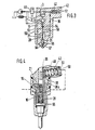
- FIG. 1 shows a pump nozzle as a fuel injection device in partial section, the parts not essential to the invention being omitted.
- a pump cylinder 2 is provided in a pump housing 1, in which a pump piston 3 is set into a reciprocating, pumping movement in a manner not shown here by a drive cam.
- the end of the pump piston 5 encloses a pump work chamber 6 in the pump cylinder 2, which is closed on the end side.
- the front-side closure of the pump cylinder 2 takes place via an intermediate piece 8, which is coaxially connected to a fuel injection valve 9, which is pressed tightly against the intermediate piece 8 by a retaining nut 11 acting on a shoulder 10 of the fuel injection valve, forming the housing unit of the pump nozzle.
- the retaining nut is screwed to the pump housing 1 and forms in its interior together with the lateral surface of the intermediate piece 8 a low pressure chamber 14 which is connected to the fuel supply source 94, which here has a fuel reservoir 91 from which a fuel pump 90 sucks fuel which can also be connected in parallel to a pressure control valve 92.
- An injection line 16 leads from the end face 15 of the pump cylinder 2, the cross-section of which is directly adjacent to the pump work space and is delimited by a conical valve seat 17 of a pressure valve 19, the injection line subsequently opening into this valve seat in an annular space 18, from which it opens in its further course in the intermediate piece 8 leads to the injection valve 9 in a known manner.
- the outlet of the injection line from the pump work area and the conical valve seat are coaxial to the axis of the pump piston.
- a guide cylinder 20 Coaxially connected to the space 18 is a guide cylinder 20 with a diameter that is larger than the outermost diameter of the conical valve seat 17.
- a pressure valve closing member 21 of the pressure valve 19 is tightly displaceable, which is loaded on its rear side by a valve spring 22 which is supported on the front side of the guide cylinder.
- the cylindrical pressure valve closing member 21 projects into the space 18 and tapers there to form a pressure shoulder 23 to form a pin 24 which carries a conical sealing surface corresponding to the valve seat 17.
- the pressure valve closing element is held on the conical seat 17 by the valve spring and closes the connection of the injection line between the pump work chamber 6 and the injection valve 9.
- the injection valve has, for example, in a known manner an inwardly opening valve needle, which has a pressure shoulder 57, to which the fuel brought to high pressure is directed via the injection line 16, through which the valve needle can be actuated in the opening direction.
- a prestressed valve closing spring 27 acts on the valve needle via a spring plate 26 located at the end of the valve needle, which spring spring is arranged in a spring chamber 28 of the injection valve and is supported at its opposite end via a spring plate 29 on the front end of the spring chamber 28.
- the cylindrical spring chamber is also coaxial with the axis of the pump piston 3.
- the pump piston 3 has in its outer surface a longitudinal groove 31, which connects the pump working space with an annular groove or partial annular groove 32. Furthermore, the longitudinal groove 31 connects the pump working space to a recess 33 in the lateral surface of the pump piston, which has a boundary edge formed at right angles to the pump piston axis on the side facing away from the pump working space and has a sloping boundary edge 35 designed as a control edge towards the pump working space.
- the partial annular groove 32 is connected to the opening of a relief channel 36 which leads from the pump cylinder 2 into a storage space 38.
- This is formed by a cylinder 39, in which a piston 40 forming a movable wall is arranged in a tightly displaceable manner, on the rear side of which a compression spring 42 is supported, which on the other hand rests on a sealing plug 43 closing the cylinder 39.
- the relief channel 36 leads from the storage space further through the pump housing 1, the intermediate piece 8 into the space 44 enclosed by the rear of the valve closing member 21 in the guide cylinder 20.
- the valve spring 22 is also arranged in this space.
- FIG. 2 which shows a section offset in the rotational position through the exemplary embodiment according to FIG. 1, shows a solenoid valve 46 which controls the connection of a fuel supply line 47 to the fuel supply source 94 with its closing element, which is not shown here in any more detail.
- the fuel supply line 47 opens into the cylinder 2 in the region of the partial annular groove 32 when the pump piston 3 is at the bottom dead center position UT shown at the end of its suction stroke.
- the pump piston 3 In operation, in the pump nozzle shown in FIG. 1, the pump piston 3 is set into a reciprocating pumping movement. In the starting position shown in the bottom dead center, the piston 40, which delimits the storage space 38, has introduced the contents of the same into the pump working space 6. In addition, a certain amount of fuel has been metered into the pump work chamber 6 via the solenoid valve. During the subsequent delivery stroke of the pump piston, the relief channel 36 is closed by the outer surface of the pump piston and remains so until it is opened again by the oblique control edge 35. In the intermediate stroke, the pump piston delivers the displaced fuel under high pressure into the injection line 16, the pressure valve closing member 21 being lifted off its seat. The injection pressure acting on the valve needle opens the fuel injection valve.
- the fuel flows into the storage space 38 with simultaneous expansion.
- the pressure which is established there is determined by the compression spring 42.
- the fuel is also conveyed into the space 44 via the relief channel 36.
- the fuel that has reached here is still at a very high pressure level, which has the effect that the forces acting in the closing direction of the pressure valve closing element 21 increase considerably and bring it into the closed position.
- the fuel delivery from the pump work space 6 into the injection line 16 or to the opening of the injection valve is interrupted.
- the pressure waves running back and forth with the closing of the injection valve in the area between valve seat 17 and injection valve needle can reduce their peaks in that the pressure valve closing member on its pressure shoulder 23 opens again and relieves the injection line 16 to the pump work chamber 6, which is now reduced Pressure level stands.
- This pressure level is determined by the spring force acting on the piston 40 and is noticeably lower than the injection pressure, but higher than the pressure of the fuel supply source.
- the closing process of the pressure valve closing member 21 is favored in that, in the first moment of actuation, an exhaust surge of the fuel compressed to high pressure of over 1000 bar reaches the space 44.
- the piston 40 loaded by a higher restoring force, has, together with the spring 42, a sufficiently large inertia behavior, so that the control shock is essentially effective on the pressure valve closing member 21.
- the fuel which is still displaced after passing over the relief channel opening is delivered into the storage space 38.
- a part of this displaced remaining fuel is initially conveyed back into the pump workspace as long as the mouth of the relief channel is in the region of the recess 33, whereas the rest of the stored fuel is conveyed into the pump workspace via the partial annular groove 32.
- the pressure level in the pump work space is considerably reduced, which favors the pushing of the fuel out of the storage space 38.
- the amount of fuel introduced into the pump work space in this way is determined by the rotational position of the pump piston or by the stroke from which the relief channel is opened by the obliquely running control edge. Then or at the same time the solenoid valve is used for the next fuel injected amount of fuel metered. Together with the amount of fuel that has already been in the pump work chamber, the point of the start of spraying then results, at which the pressure in the pump work chamber is increased to such an extent that the opening pressure of the injection valve is reached.
- the rotational position of the pump piston determines the end of spraying and at the same time the start of spraying with a constant fuel quantity via the solenoid valve. With the help of the solenoid valve, the amount of fuel to be injected per pump stroke is determined and at the same time the start of injection is influenced.
- the fuel pressure acts on the entire cross section, which leads to a noticeably faster evasion of the pressure valve closing member 21.
- This provides a swallowing volume that initially slows down the further increase in fuel pressure, which is also associated with a lower injection rate.
- this is entirely in line with the initially delayed introduction of fuel into the combustion chamber, since an ignition delay time is to be expected at the start of injection. It is thus avoided that too much fuel suddenly ignites after the end of this delay time and generates an undesirable combustion noise (knocking, nailing).
- the evasive stroke of the pressure valve closing member 21 is determined by its stop 49 at the end of the guide cylinder 20. The stroke of the pressure valve closing member is adapted to the effects to be achieved.
- the fuel volume displaced by the pressure valve closing element during the opening process is returned to the storage space 38.
- the characteristic of the accumulator then additionally determines the evasion speed of the pressure valve closing element, since this compresses fuel on its rear side during its evasion process.
- the pressure which is established is determined by the piston 40 of the accumulator. This also gives you the option to intervene in the injection process at the start of injection.
- the dynamic behavior of the piston 40 can also be controlled by applying fuel pressure to the rear of the piston 40.
- the space 51 can also be connected to the low-pressure space 14, which is relieved of pressure to the fuel reservoir or to the suction side of the fuel delivery pump, or also to pressure levels controlled by a pressure source.
- the relief duct can also open into the spring space 28 or into the pressure line 53.
- the spring chamber can advantageously also be connected to the low-pressure side or the low-pressure chamber 14 via a connection 59 which is throttled in relation to the inflow cross section, as a result of which a flushing effect is achieved. If necessary, in the latter version, an additional throttle 58 in the. Line 53 may be arranged, which, together with the throttle 54, influences the dynamic effect of the control surge in the spring chamber 28 and in the chamber 44.
- the exemplary embodiment according to FIG. 4 is an embodiment which is likewise implemented on a pump nozzle as in the exemplary embodiment according to FIG. 1. Essentially the same parts are present here, only the relief channel 36 initially ends in the storage space 38. On the rear side of the storage piston 40, the space 51 is in turn enclosed, but now via a pressure line 36a branching off there as a continuation of the relief channel 36 into the spring space 28 of the Fuel injector leads. In this exemplary embodiment, only the injection valve closing member 55 is acted upon in the closing direction by the control surge, the pressure valve 19, on the other hand, operates in the usual way.
- This device specifically increases the closing pressure at the end of the spray, with hydraulic separation between the relief channel 36 and the further relief channel 36a or spring chamber 28 in the sense of precise metering.
- the exhaust surge also reaches the spring chamber, but it is decoupled as a harmful volume during the suction phase of fuel in the pump work chamber during the suction stroke of the pump piston.
- the hydraulic spaces, which comprise the space 51 and the space 28, are pressure-balanced at the point in time at which the relief channel 36 is opened, for which purpose a throttle connection 50 to a low-pressure space corresponding to the configuration according to FIG. 1 can be used.
- the volume decoupling via the piston 40 shown in the exemplary embodiment in FIG. 4 can of course also be transferred to the designs shown in FIGS. 1 and 3 with pressurization of the spring space and the space 44 enclosed by the valve closing member. This also results in the corresponding advantages described there in connection with the uncoupling of the harmful volume behind the piston 40.
- FIG. 4 A development of the embodiment according to FIG. 4 shows the piston 40 'in the embodiment according to FIG. 5.
- the piston 40' can also be displaced tightly in the cylinder 39 and encloses the storage space 38 with its one end face in this cylinder, which via the relief channel 36 communicates with the pump cylinder 2.
- the rear of the accumulator piston 40 ' is also acted upon by the compression spring 42 which is supported on the end face of the closure piece 43' which closes the cylinder 39.
- the storage piston 40 ' is pot-shaped and has on its rear side acted upon by the spring 42 a piston 64 which extends coaxially to the storage piston axis and which is surrounded by the compression spring 42 and cooperates with a working cylinder 65 which is arranged in the closure piece 43' and there includes a work space 68.
- the piston 64 In the rest position of the accumulator piston 40 'shown, the piston 64 is located outside the working cylinder 65.
- the pressure chamber connected can be relieved during the opening stroke of the injection valve closing member without a pressure which hinders the opening stroke building up in the pressure chamber.
- the piston 64 displaces the fuel contained in the working cylinder 65.
- the chamber 51 enclosed by the rear side of the accumulator piston 40 ' is connected to a fuel source via a line 66 low pressure, in a similar manner to that already described in Figure 1.
- the working space 68 enclosed by the piston 64 can also be connected via a throttle 67 to the low-pressure space or space 51.
- the throttle can, as shown in FIG a connecting line between the further relief channel 36a "and the line 66, or the piston 64 can have a throttle gap with respect to the cylinder diameter of the working cylinder 65. This can also be produced separately by means of a corresponding recess, bevel or bore.
- a stepped piston is realized, which permits pressure translation in such a way that a higher pressure is generated in the working space 68 than in the storage space 38.
- the configuration can thus serve to increase the pressure in the spring chamber 28 or in the chamber 44 even more, with the additional advantage of hydraulic separation.
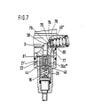
- FIG. 6 shows an embodiment variant in which a high additional closing force on the valve closing member of the fuel injection valve can be generated with the aid of the exhaust surge with the lowest possible pressure volume.
- the relief duct 36 or the further relief duct 36a, 36a ', 36a "opens into a pressure chamber 69, which is enclosed in a cylinder 71 by an end part 74 of a stamp-like extension part 70 of the injection valve closing element 55 or the valve plate 26 70 surrounding spring chamber 28 'is relieved of pressure via a leakage line 72.
- throttle connection 73' between the pressure chamber 69 and the spring chamber 28 ', which can also be realized in that the stamp part 74 is guided with play in the cylinder 71 or with it
- the throttle connection prevents the pressure in the pressure chamber 69 from rising to high values, and also avoids excessive obstruction of the valve needle opening movement if this embodiment is combined with the embodiment according to FIG In combination with the configuration according to FIG. 5, on the other hand, is already the dro provided 67 through which the purpose just described is already achieved. With this configuration, a high additional closing force can be applied to the valve closing member of the injection valve at the end of the spraying process, without the inherent elasticity of the hydraulic space, for example the spring chamber 28, making part of the energy of the control shock ineffective.
- the storage piston 40 " is now designed such that it has a frustoconical end face 75 toward the storage space 38 '.
- the lateral surfaces 76 of this frustoconical end face 75 are designed as sealing surfaces which are provided with an annular, into the storage space 38' projecting web 77 as a valve seat.
- the web 77 is designed as an insert in the cylinder guiding the piston 40 ", which seals tightly with the cylinder wall and divides the storage space 38 'into a first partial storage space 78 and a second partial storage space 79 when the storage piston 40" is in contact
- the second partial storage space 79 is connected directly to the pump cylinder 2, while the first partial storage space 78 is connected to the further relief channel 36a "'.
- the first partial storage space 78 is delimited by the outermost part 80 of the conical lateral surface 76 in the axial direction of the pump piston. This surface 80 serves as a pressure shoulder, via which the piston 40 ′′ can be deflected from its rest position on the web 77 when the pressure in the spring chamber 28 or pressure chamber 44 increases. This takes place in particular when the fuel injection valve opens or the valve closing member 21 is brought into the open position.
- the fuel displaced in the process is stored in the storage space 38 ′′ and can be compensated for with the exhaust surge. Thus, no fuel is lost to the exact fuel metering via leak lines, which were necessary in particular to avoid excessive pressure in the spring chamber 28 or chamber 44 in the other exemplary embodiments.
- a pressure valve closing member 21 ' is also provided in a modified form, which corresponds in its arrangement to the exemplary embodiment according to FIG. 3 or FIG. 1, but which plunges into the injection line section 82 between the space 18 and the pump working space with a pin 81 if that Pressure valve closing member 21 goes into the closed position.
- the space 44 enclosed at the rear of the valve closing member 21 ' is connected to the spring space 28 as in the exemplary embodiment according to FIG. 3 and via this to the storage space 38'.
- the pressure valve closing member 21 is first deflected against the force of the valve spring 22 until the pin 81 completely emerges from the injection line section 82 and establishes the connection between the pump work chamber 6 and the chamber 18. Only then can the high pressure spread unthrottled via the further injection line 16 to the injection valve.
- the injection line 16 or the volume between the pressure valve closing member and valve needle 55 is somewhat relieved and must first be filled up by the fuel displaced by the pump piston.
- the pressure valve closing member 21 ' continues its evasive movement until it reaches the stop 49 already known from FIG.
- the exemplary embodiment according to FIGS. 8 and 9 works with a pump nozzle in which the fuel quantity to be injected per pump piston stroke is controlled with the aid of a solenoid valve which, unlike the previous exemplary embodiments, has a valve closing member which on the one hand is subject to the pump delivery pressure during the entire pump piston delivery stroke hit.
- This type of fuel injector does not require the storage space 38 described in the aforementioned examples, since the phase in which this valve is closed alone determines the fuel injection quantity and the injection timing.
- this device advantageously also works together with a pressure valve closing element 21 ′′ as in the previous exemplary embodiments, and the exhaust surge is also used to generate an additional force on the valve closing element of the injection valve and / or the pressure valve closing element.
- FIG. 8 shows part of a fuel injection device in section. This also builds on a fuel injection device, such as those shown in FIGS. 1, 4 and 8. This is also a so-called pump nozzle. In principle, however, the configuration based on this exemplary pump could also be implemented in other fuel injection pumps. When designing a pump nozzle, however, there are the advantages of a short injection time with high injection pressure, already mentioned in the above exemplary embodiments, while avoiding harmful line influences between the fuel injection pump and the fuel injection valve. Of the pump nozzle, only the pump piston 103 is shown in the embodiment in FIG. 8, which is driven by means already mentioned in the previous example and slides in the pump housing 101 in a pump cylinder 102 and encloses the pump working space 106 there.
- an intermediate piece 108 adjoins the pump housing 101, in which the pressure valve closing element 121 is arranged in the same configuration in the guide cylinder 120.
- the pressure valve closing member 121 has a sealing surface which cooperates with a conical valve seat 117 and has a pressure shoulder 123 which is exposed to the pressure in the space 118 adjoining the valve seat 117 and, when pressure is applied, the pressure valve closing member counteracts its valve spring 122 up to a stop 149 at the end of the guide cylinder moves.
- the intermediate piece 108 there is also a relief and filling channel 136, the connection to the pump work space 106 of which is controlled via a solenoid valve or electrically controllable valve 84.
- the electrically controllable valve is controlled by an electrical control device 85 as a function of the operating parameters of the internal combustion engine.
- the relief and filling channel 136 is divided into a first further partial channel 136a and a second partial channel 86, which opens into the guide cylinder 120 at the stop-side end thereof.
- the intermediate piece 108 is followed by a second intermediate piece 87, against which the housing 109 of the fuel injection valve comes into contact and is screwed with a nut similar to the nut 11 in FIG.
- the first part 136a leads into a pressure chamber 169, as is already shown in FIG. 7 and which is enclosed by a stamp-shaped extension part 170, which is connected to the valve closing member 155 of the fuel injection valve.
- the valve spring chamber 128 which receives the extension part 170 and also contains the injection valve closing spring 127 has a throttle connection 173 to the pressure chamber 169, or the pressure chamber 169 has a throttle connection 88 to a fuel supply line 89 which is fed by a fuel feed pump 90 from a fuel reservoir 91, the fuel feed pump together with a pressure control valve 92 serves as a constant pressure fuel supply source from which the pump arm beitsraum can be supplied with fuel and to which the amount of fuel not required for injection can flow out.
- the fuel supply line 89 is also connected to the space 144 enclosed by the pressure valve closing element 121 in the guide cylinder 120, which in turn can be connected to the relief and filling channel 136 via the second sub-channel 86. In this way, during the suction stroke of the pump piston, with the electrically controlled valve 84 open, the pump working space 106 can be filled with fuel via the relief and filling channel 136.
- the second sub-channel 86 is controlled by the outer surface of the pressure valve closing element together with the stop edge 93 of the same.
- this leading edge has opened the second sub-channel 86.
- This state corresponds to the suction stroke of the pump piston 103.
- this fuel can convey back into the fuel supply line 89 in the same way, as long as the electrically controlled valve 84 is open.
- the valve 84 closes the relief channel 136.
- the pressure valve closing member opens under the increasing pressure in the pump work space 106 and the fuel delivered can reach the fuel injection valve via the fuel injection line 116.
- the electrically controlled valve 84 opens the relief channel 136 again and the remaining fuel delivered by the pump piston flows directly into the pressure chamber 169, since at this point in time the pressure valve closing element 121 initially closes the second sub-channel 86 and thus also the Has closed connection to the fuel supply line 89 or to the relief chamber.
- a high pressure can build up in the pressure chamber 169 in support of the closing movement of the valve closing element of the fuel injection valve.
- the throttle connection 88 or 173 With the throttle connection 88 or 173, the pump work space is relieved after the end of the injection.
- the pressure valve closing element is moved upward by its valve spring towards the valve seat 117, the second subchannel 86 also opening at the same time.
- the second subchannel 86 can also open, as shown in FIG. 10, in an annular groove 95 provided in the wall of the guide cylinder 120, which is likewise controlled by a control edge provided on the outer surface of the pressure valve closing element becomes.
- the fuel injection valve closes very quickly at the end of the injection time, the end of the injection time being essentially determined by the build-up of the pressure in the pressure chamber 169 and not by the relief of the pump work chamber with subsequent closing of the pressure valve closing element.
- the force acting on the fuel injection valve closing member can be determined.
- the free cross-section of the throttle connection 88 or 173 must also be taken into account.
Landscapes
- Engineering & Computer Science (AREA)
- Chemical & Material Sciences (AREA)
- Combustion & Propulsion (AREA)
- Mechanical Engineering (AREA)
- General Engineering & Computer Science (AREA)
- Fuel-Injection Apparatus (AREA)
Priority Applications (1)
| Application Number | Priority Date | Filing Date | Title |
|---|---|---|---|
| AT86106497T ATE69488T1 (de) | 1985-06-14 | 1986-05-13 | Kraftstoffeinspritzvorrichtung fuer brennkraftmaschinen. |
Applications Claiming Priority (2)
| Application Number | Priority Date | Filing Date | Title |
|---|---|---|---|
| DE3521428 | 1985-06-14 | ||
| DE19853521428 DE3521428A1 (de) | 1985-06-14 | 1985-06-14 | Kraftstoffeinspritzvorrichtung fuer brennkraftmaschinen |
Publications (3)
| Publication Number | Publication Date |
|---|---|
| EP0204982A2 true EP0204982A2 (fr) | 1986-12-17 |
| EP0204982A3 EP0204982A3 (en) | 1989-02-22 |
| EP0204982B1 EP0204982B1 (fr) | 1991-11-13 |
Family
ID=6273327
Family Applications (1)
| Application Number | Title | Priority Date | Filing Date |
|---|---|---|---|
| EP19860106497 Expired - Lifetime EP0204982B1 (fr) | 1985-06-14 | 1986-05-13 | Dispositif d'injection de combustible pour moteurs à combustion interne |
Country Status (5)
| Country | Link |
|---|---|
| US (1) | US4750462A (fr) |
| EP (1) | EP0204982B1 (fr) |
| JP (1) | JPS61291764A (fr) |
| AT (1) | ATE69488T1 (fr) |
| DE (2) | DE3521428A1 (fr) |
Cited By (3)
| Publication number | Priority date | Publication date | Assignee | Title |
|---|---|---|---|---|
| EP0372238A1 (fr) * | 1988-12-02 | 1990-06-13 | Robert Bosch Gmbh | Pompe d'injection de combustible pour moteurs à combustion interne |
| CH677132A5 (en) * | 1990-01-05 | 1991-04-15 | Sulzer Ag | Injection device for reciprocating piston engine - has valve closure member with piston section in valve chamber bore |
| EP0377103B1 (fr) * | 1988-12-31 | 1992-08-26 | Robert Bosch Gmbh | Dispositif d'injection de combustible |
Families Citing this family (10)
| Publication number | Priority date | Publication date | Assignee | Title |
|---|---|---|---|---|
| JP2523759B2 (ja) * | 1987-02-04 | 1996-08-14 | フエスト − アルピネ オウトモチブ ゲゼルシャフト ミットベシュレンクテル ハフツンク | 燃料噴射ノズル |
| US5282574A (en) * | 1991-12-19 | 1994-02-01 | Caterpillar Inc. | Hydraulic flow shutoff device for a unit fuel pump/injector |
| GB9506959D0 (en) * | 1995-04-04 | 1995-05-24 | Lucas Ind Plc | Fuel system |
| US6047899A (en) * | 1998-02-13 | 2000-04-11 | Caterpillar Inc. | Hydraulically-actuated fuel injector with abrupt end to injection features |
| US6059203A (en) * | 1998-09-03 | 2000-05-09 | Caterpillar Inc. | Valve assembly with concentrically linked components and fuel injector using same |
| DE10119603A1 (de) * | 2001-04-21 | 2002-10-24 | Bosch Gmbh Robert | Kraftsotffeinspritzeinrichtung für eine Brennkraftmaschine |
| DE10119602A1 (de) * | 2001-04-21 | 2002-10-24 | Bosch Gmbh Robert | Kraftstoffeinspritzeinrichtung für eine Brennkraftmaschine |
| DE10143947A1 (de) * | 2001-09-07 | 2003-04-03 | Bosch Gmbh Robert | Injektorkörper mit tangentialem Druckanschluss |
| DE10155973A1 (de) * | 2001-11-14 | 2003-05-22 | Bosch Gmbh Robert | Kraftstoffeinspritzeinrichtung für eine Brennkraftmaschine |
| DE10207974A1 (de) * | 2002-02-25 | 2003-09-18 | Bosch Gmbh Robert | Geräuschoptimierte Einrichtung zum Einspritzen von Kraftstoff |
Citations (9)
| Publication number | Priority date | Publication date | Assignee | Title |
|---|---|---|---|---|
| DE585015C (de) * | 1932-09-24 | 1933-09-27 | Robert Bosch Akt Ges | Anordnung des Sicherheitsventils bei Einspritzpumpen fuer Brennkraftmaschinen |
| US2628570A (en) * | 1946-04-26 | 1953-02-17 | American Bosch Corp | Fuel injection device |
| US3115304A (en) * | 1961-10-11 | 1963-12-24 | Gen Motors Corp | Fuel injector pump with hydraulically controlled injection valve |
| US3810453A (en) * | 1971-10-18 | 1974-05-14 | G Wolfe | Fuel injection system |
| US3818882A (en) * | 1972-03-27 | 1974-06-25 | O Leonov | Fuel system of internal combustion engine |
| DE2301419A1 (de) * | 1973-01-12 | 1974-07-18 | Bosch Gmbh Robert | Kraftstoffeinspritzanlage |
| FR2366460A1 (fr) * | 1976-10-04 | 1978-04-28 | Friedmann & Maier Ag | Dispositif d'injection de carburant |
| US4317541A (en) * | 1980-07-10 | 1982-03-02 | General Motors Corporation | Fuel injector-pump unit with hydraulic needle fuel injector |
| EP0132798A2 (fr) * | 1983-07-29 | 1985-02-13 | Robert Bosch Gmbh | Pompe-injecteur pour l'injection du combustible dans des moteurs à combustion interne |
Family Cites Families (9)
| Publication number | Priority date | Publication date | Assignee | Title |
|---|---|---|---|---|
| US2950709A (en) * | 1956-08-14 | 1960-08-30 | Bessiere Pierre Etienne | Injection devices including a reciprocating piston injection pump |
| DE2126777A1 (de) * | 1971-05-28 | 1972-12-14 | Bosch Gmbh Robert | Pumpe Düse zur Kraftstoffeinspritzung fur Brennkraftmaschinen |
| US4129256A (en) * | 1977-09-12 | 1978-12-12 | General Motors Corporation | Electromagnetic unit fuel injector |
| DE3023731A1 (de) * | 1980-06-25 | 1982-01-14 | Mtu Motoren- Und Turbinen-Union Friedrichshafen Gmbh, 7990 Friedrichshafen | Einspritzpumpe |
| JPS5738631A (en) * | 1980-07-01 | 1982-03-03 | Bosch Gmbh Robert | Fuel injection method of and apparatus for internal combustion engine |
| US4475515A (en) * | 1981-09-05 | 1984-10-09 | Lucas Industries Public Limited Company | Fuel systems for compression ignition engines |
| DE3307826A1 (de) * | 1983-03-05 | 1984-09-06 | Robert Bosch Gmbh, 7000 Stuttgart | Kraftstoffeinspritzeinrichtung fuer brennkraftmaschinen |
| US4527737A (en) * | 1983-09-09 | 1985-07-09 | General Motors Corporation | Electromagnetic unit fuel injector with differential valve |
| DE3411407A1 (de) * | 1984-03-28 | 1985-10-03 | Robert Bosch Gmbh, 7000 Stuttgart | Pumpduese fuer die kraftstoffeinspritzung bei brennkraftmaschinen |
-
1985
- 1985-06-14 DE DE19853521428 patent/DE3521428A1/de not_active Ceased
-
1986
- 1986-05-13 AT AT86106497T patent/ATE69488T1/de active
- 1986-05-13 EP EP19860106497 patent/EP0204982B1/fr not_active Expired - Lifetime
- 1986-05-13 DE DE8686106497T patent/DE3682439D1/de not_active Expired - Lifetime
- 1986-06-11 US US06/873,002 patent/US4750462A/en not_active Expired - Fee Related
- 1986-06-13 JP JP61136368A patent/JPS61291764A/ja active Pending
Patent Citations (9)
| Publication number | Priority date | Publication date | Assignee | Title |
|---|---|---|---|---|
| DE585015C (de) * | 1932-09-24 | 1933-09-27 | Robert Bosch Akt Ges | Anordnung des Sicherheitsventils bei Einspritzpumpen fuer Brennkraftmaschinen |
| US2628570A (en) * | 1946-04-26 | 1953-02-17 | American Bosch Corp | Fuel injection device |
| US3115304A (en) * | 1961-10-11 | 1963-12-24 | Gen Motors Corp | Fuel injector pump with hydraulically controlled injection valve |
| US3810453A (en) * | 1971-10-18 | 1974-05-14 | G Wolfe | Fuel injection system |
| US3818882A (en) * | 1972-03-27 | 1974-06-25 | O Leonov | Fuel system of internal combustion engine |
| DE2301419A1 (de) * | 1973-01-12 | 1974-07-18 | Bosch Gmbh Robert | Kraftstoffeinspritzanlage |
| FR2366460A1 (fr) * | 1976-10-04 | 1978-04-28 | Friedmann & Maier Ag | Dispositif d'injection de carburant |
| US4317541A (en) * | 1980-07-10 | 1982-03-02 | General Motors Corporation | Fuel injector-pump unit with hydraulic needle fuel injector |
| EP0132798A2 (fr) * | 1983-07-29 | 1985-02-13 | Robert Bosch Gmbh | Pompe-injecteur pour l'injection du combustible dans des moteurs à combustion interne |
Cited By (3)
| Publication number | Priority date | Publication date | Assignee | Title |
|---|---|---|---|---|
| EP0372238A1 (fr) * | 1988-12-02 | 1990-06-13 | Robert Bosch Gmbh | Pompe d'injection de combustible pour moteurs à combustion interne |
| EP0377103B1 (fr) * | 1988-12-31 | 1992-08-26 | Robert Bosch Gmbh | Dispositif d'injection de combustible |
| CH677132A5 (en) * | 1990-01-05 | 1991-04-15 | Sulzer Ag | Injection device for reciprocating piston engine - has valve closure member with piston section in valve chamber bore |
Also Published As
| Publication number | Publication date |
|---|---|
| ATE69488T1 (de) | 1991-11-15 |
| JPS61291764A (ja) | 1986-12-22 |
| US4750462A (en) | 1988-06-14 |
| EP0204982A3 (en) | 1989-02-22 |
| DE3682439D1 (de) | 1991-12-19 |
| DE3521428A1 (de) | 1986-12-18 |
| EP0204982B1 (fr) | 1991-11-13 |
Similar Documents
| Publication | Publication Date | Title |
|---|---|---|
| EP0685646B1 (fr) | Dispositif d'injection de combustible pour moteurs à combustion interne | |
| EP0116168B1 (fr) | Pompe d'injection de combustible | |
| EP0163078B1 (fr) | Soupape de refoulement | |
| DE2558789C2 (fr) | ||
| EP0141044B1 (fr) | Dispositif d'injection de carburant avec pré-injection et injection principale dans un moteur à combustion interne | |
| DE3910793C2 (de) | Brennstoffeinspritzvorrichtung | |
| DE3521427C2 (fr) | ||
| DE3217887A1 (de) | Kraftstoff-einspritzsystem fuer brennkraftmaschinen | |
| EP0375928B1 (fr) | Dispositif d'injection de combustible | |
| DE2643466A1 (de) | Kraftstoffeinspritzpumpe | |
| EP0204982B1 (fr) | Dispositif d'injection de combustible pour moteurs à combustion interne | |
| DE2704688A1 (de) | Kraftstoffeinspritzvorrichtung | |
| EP0688950B1 (fr) | Système d'injection de carburant | |
| EP0290797B1 (fr) | Pompe d'injection de combustible | |
| DE3719831A1 (de) | Kraftstoffeinspritzpumpe | |
| EP0150471B1 (fr) | Pompe d'injection de combustible | |
| EP1141539A1 (fr) | Pompe a piston pour carburant sous haute pression | |
| DE19531870C2 (de) | Kraftstoffeinspritzsystem | |
| EP0502315A1 (fr) | Pompe d'injection de combustible pour moteurs à combustion interne | |
| DE3524241A1 (de) | Kraftstoffeinspritzpumpe fuer brennkraftmaschinen | |
| DE4304967A1 (de) | Kraftstoffeinspritzeinrichtung für Brennkraftmaschinen | |
| DE3236828A1 (de) | Brennstoffeinspritzvorrichtung | |
| DE10023960A1 (de) | Kraftstoffeinspritzvorrichtung für eine Brennkraftmaschine | |
| DE4006084A1 (de) | Verfahren und verminderung der resteinspritzmenge von einspritzpumpen | |
| DE3436042A1 (de) | Kraftstoffeinspritzpumpe fuer selbstzuendende brennkraftmaschinen |
Legal Events
| Date | Code | Title | Description |
|---|---|---|---|
| PUAI | Public reference made under article 153(3) epc to a published international application that has entered the european phase |
Free format text: ORIGINAL CODE: 0009012 |
|
| AK | Designated contracting states |
Kind code of ref document: A2 Designated state(s): AT DE FR GB IT |
|
| PUAL | Search report despatched |
Free format text: ORIGINAL CODE: 0009013 |
|
| AK | Designated contracting states |
Kind code of ref document: A3 Designated state(s): AT DE FR GB IT |
|
| 17P | Request for examination filed |
Effective date: 19890718 |
|
| 17Q | First examination report despatched |
Effective date: 19891026 |
|
| GRAA | (expected) grant |
Free format text: ORIGINAL CODE: 0009210 |
|
| AK | Designated contracting states |
Kind code of ref document: B1 Designated state(s): AT DE FR GB IT |
|
| REF | Corresponds to: |
Ref document number: 69488 Country of ref document: AT Date of ref document: 19911115 Kind code of ref document: T |
|
| ET | Fr: translation filed | ||
| REF | Corresponds to: |
Ref document number: 3682439 Country of ref document: DE Date of ref document: 19911219 |
|
| GBT | Gb: translation of ep patent filed (gb section 77(6)(a)/1977) | ||
| ITF | It: translation for a ep patent filed |
Owner name: STUDIO JAUMANN |
|
| RAP4 | Party data changed (patent owner data changed or rights of a patent transferred) |
Owner name: ROBERT BOSCH GMBH |
|
| PGFP | Annual fee paid to national office [announced via postgrant information from national office to epo] |
Ref country code: AT Payment date: 19920428 Year of fee payment: 7 |
|
| PLBE | No opposition filed within time limit |
Free format text: ORIGINAL CODE: 0009261 |
|
| STAA | Information on the status of an ep patent application or granted ep patent |
Free format text: STATUS: NO OPPOSITION FILED WITHIN TIME LIMIT |
|
| 26N | No opposition filed | ||
| PG25 | Lapsed in a contracting state [announced via postgrant information from national office to epo] |
Ref country code: AT Effective date: 19930513 |
|
| PGFP | Annual fee paid to national office [announced via postgrant information from national office to epo] |
Ref country code: GB Payment date: 19940504 Year of fee payment: 9 |
|
| PGFP | Annual fee paid to national office [announced via postgrant information from national office to epo] |
Ref country code: FR Payment date: 19940530 Year of fee payment: 9 |
|
| PGFP | Annual fee paid to national office [announced via postgrant information from national office to epo] |
Ref country code: DE Payment date: 19940727 Year of fee payment: 9 |
|
| PG25 | Lapsed in a contracting state [announced via postgrant information from national office to epo] |
Ref country code: GB Effective date: 19950513 |
|
| GBPC | Gb: european patent ceased through non-payment of renewal fee |
Effective date: 19950513 |
|
| PG25 | Lapsed in a contracting state [announced via postgrant information from national office to epo] |
Ref country code: DE Effective date: 19960201 |
|
| PG25 | Lapsed in a contracting state [announced via postgrant information from national office to epo] |
Ref country code: FR Effective date: 19960229 |
|
| REG | Reference to a national code |
Ref country code: FR Ref legal event code: ST |
|
| REG | Reference to a national code |
Ref country code: FR Ref legal event code: ST |
|
| PG25 | Lapsed in a contracting state [announced via postgrant information from national office to epo] |
Ref country code: IT Free format text: LAPSE BECAUSE OF NON-PAYMENT OF DUE FEES;WARNING: LAPSES OF ITALIAN PATENTS WITH EFFECTIVE DATE BEFORE 2007 MAY HAVE OCCURRED AT ANY TIME BEFORE 2007. THE CORRECT EFFECTIVE DATE MAY BE DIFFERENT FROM THE ONE RECORDED. Effective date: 20050513 |