EP0204889A2 - Absturzsicherung in Kombination mit einer Vorrichtung zum Ausziehen eines Rohres aus einem Rohrboden eines Wärmetauschers - Google Patents
Absturzsicherung in Kombination mit einer Vorrichtung zum Ausziehen eines Rohres aus einem Rohrboden eines Wärmetauschers Download PDFInfo
- Publication number
- EP0204889A2 EP0204889A2 EP86102316A EP86102316A EP0204889A2 EP 0204889 A2 EP0204889 A2 EP 0204889A2 EP 86102316 A EP86102316 A EP 86102316A EP 86102316 A EP86102316 A EP 86102316A EP 0204889 A2 EP0204889 A2 EP 0204889A2
- Authority
- EP
- European Patent Office
- Prior art keywords
- cylinder
- hollow piston
- chamber
- heat exchanger
- rodless cylinder
- Prior art date
- Legal status (The legal status is an assumption and is not a legal conclusion. Google has not performed a legal analysis and makes no representation as to the accuracy of the status listed.)
- Granted
Links
- 238000000034 method Methods 0.000 claims abstract description 10
- 230000001105 regulatory effect Effects 0.000 claims abstract description 3
- 210000000078 claw Anatomy 0.000 claims description 6
- 230000006835 compression Effects 0.000 claims description 5
- 238000007906 compression Methods 0.000 claims description 5
- 230000001276 controlling effect Effects 0.000 claims description 4
- 239000000853 adhesive Substances 0.000 description 1
- 230000001070 adhesive effect Effects 0.000 description 1
- 239000002826 coolant Substances 0.000 description 1
- 238000007689 inspection Methods 0.000 description 1
- 230000005855 radiation Effects 0.000 description 1
Images


Classifications
-
- F—MECHANICAL ENGINEERING; LIGHTING; HEATING; WEAPONS; BLASTING
- F22—STEAM GENERATION
- F22B—METHODS OF STEAM GENERATION; STEAM BOILERS
- F22B37/00—Component parts or details of steam boilers
- F22B37/02—Component parts or details of steam boilers applicable to more than one kind or type of steam boiler
- F22B37/58—Removing tubes from headers or drums; Extracting tools
-
- B—PERFORMING OPERATIONS; TRANSPORTING
- B25—HAND TOOLS; PORTABLE POWER-DRIVEN TOOLS; MANIPULATORS
- B25B—TOOLS OR BENCH DEVICES NOT OTHERWISE PROVIDED FOR, FOR FASTENING, CONNECTING, DISENGAGING OR HOLDING
- B25B27/00—Hand tools, specially adapted for fitting together or separating parts or objects whether or not involving some deformation, not otherwise provided for
- B25B27/02—Hand tools, specially adapted for fitting together or separating parts or objects whether or not involving some deformation, not otherwise provided for for connecting objects by press fit or detaching same
-
- B—PERFORMING OPERATIONS; TRANSPORTING
- B23—MACHINE TOOLS; METAL-WORKING NOT OTHERWISE PROVIDED FOR
- B23P—METAL-WORKING NOT OTHERWISE PROVIDED FOR; COMBINED OPERATIONS; UNIVERSAL MACHINE TOOLS
- B23P19/00—Machines for simply fitting together or separating metal parts or objects, or metal and non-metal parts, whether or not involving some deformation; Tools or devices therefor so far as not provided for in other classes
- B23P19/02—Machines for simply fitting together or separating metal parts or objects, or metal and non-metal parts, whether or not involving some deformation; Tools or devices therefor so far as not provided for in other classes for connecting objects by press fit or for detaching same
- B23P19/025—For detaching only
-
- F—MECHANICAL ENGINEERING; LIGHTING; HEATING; WEAPONS; BLASTING
- F22—STEAM GENERATION
- F22B—METHODS OF STEAM GENERATION; STEAM BOILERS
- F22B37/00—Component parts or details of steam boilers
- F22B37/002—Component parts or details of steam boilers specially adapted for nuclear steam generators, e.g. maintenance, repairing or inspecting equipment not otherwise provided for
- F22B37/003—Maintenance, repairing or inspecting equipment positioned in or via the headers
-
- Y—GENERAL TAGGING OF NEW TECHNOLOGICAL DEVELOPMENTS; GENERAL TAGGING OF CROSS-SECTIONAL TECHNOLOGIES SPANNING OVER SEVERAL SECTIONS OF THE IPC; TECHNICAL SUBJECTS COVERED BY FORMER USPC CROSS-REFERENCE ART COLLECTIONS [XRACs] AND DIGESTS
- Y10—TECHNICAL SUBJECTS COVERED BY FORMER USPC
- Y10S—TECHNICAL SUBJECTS COVERED BY FORMER USPC CROSS-REFERENCE ART COLLECTIONS [XRACs] AND DIGESTS
- Y10S29/00—Metal working
- Y10S29/042—Tension applied during working
-
- Y—GENERAL TAGGING OF NEW TECHNOLOGICAL DEVELOPMENTS; GENERAL TAGGING OF CROSS-SECTIONAL TECHNOLOGIES SPANNING OVER SEVERAL SECTIONS OF THE IPC; TECHNICAL SUBJECTS COVERED BY FORMER USPC CROSS-REFERENCE ART COLLECTIONS [XRACs] AND DIGESTS
- Y10—TECHNICAL SUBJECTS COVERED BY FORMER USPC
- Y10T—TECHNICAL SUBJECTS COVERED BY FORMER US CLASSIFICATION
- Y10T29/00—Metal working
- Y10T29/49—Method of mechanical manufacture
- Y10T29/49815—Disassembling
- Y10T29/49822—Disassembling by applying force
-
- Y—GENERAL TAGGING OF NEW TECHNOLOGICAL DEVELOPMENTS; GENERAL TAGGING OF CROSS-SECTIONAL TECHNOLOGIES SPANNING OVER SEVERAL SECTIONS OF THE IPC; TECHNICAL SUBJECTS COVERED BY FORMER USPC CROSS-REFERENCE ART COLLECTIONS [XRACs] AND DIGESTS
- Y10—TECHNICAL SUBJECTS COVERED BY FORMER USPC
- Y10T—TECHNICAL SUBJECTS COVERED BY FORMER US CLASSIFICATION
- Y10T29/00—Metal working
- Y10T29/51—Plural diverse manufacturing apparatus including means for metal shaping or assembling
- Y10T29/5199—Work on tubes
-
- Y—GENERAL TAGGING OF NEW TECHNOLOGICAL DEVELOPMENTS; GENERAL TAGGING OF CROSS-SECTIONAL TECHNOLOGIES SPANNING OVER SEVERAL SECTIONS OF THE IPC; TECHNICAL SUBJECTS COVERED BY FORMER USPC CROSS-REFERENCE ART COLLECTIONS [XRACs] AND DIGESTS
- Y10—TECHNICAL SUBJECTS COVERED BY FORMER USPC
- Y10T—TECHNICAL SUBJECTS COVERED BY FORMER US CLASSIFICATION
- Y10T29/00—Metal working
- Y10T29/53—Means to assemble or disassemble
- Y10T29/53113—Heat exchanger
-
- Y—GENERAL TAGGING OF NEW TECHNOLOGICAL DEVELOPMENTS; GENERAL TAGGING OF CROSS-SECTIONAL TECHNOLOGIES SPANNING OVER SEVERAL SECTIONS OF THE IPC; TECHNICAL SUBJECTS COVERED BY FORMER USPC CROSS-REFERENCE ART COLLECTIONS [XRACs] AND DIGESTS
- Y10—TECHNICAL SUBJECTS COVERED BY FORMER USPC
- Y10T—TECHNICAL SUBJECTS COVERED BY FORMER US CLASSIFICATION
- Y10T29/00—Metal working
- Y10T29/53—Means to assemble or disassemble
- Y10T29/53657—Means to assemble or disassemble to apply or remove a resilient article [e.g., tube, sleeve, etc.]
-
- Y—GENERAL TAGGING OF NEW TECHNOLOGICAL DEVELOPMENTS; GENERAL TAGGING OF CROSS-SECTIONAL TECHNOLOGIES SPANNING OVER SEVERAL SECTIONS OF THE IPC; TECHNICAL SUBJECTS COVERED BY FORMER USPC CROSS-REFERENCE ART COLLECTIONS [XRACs] AND DIGESTS
- Y10—TECHNICAL SUBJECTS COVERED BY FORMER USPC
- Y10T—TECHNICAL SUBJECTS COVERED BY FORMER US CLASSIFICATION
- Y10T29/00—Metal working
- Y10T29/53—Means to assemble or disassemble
- Y10T29/53796—Puller or pusher means, contained force multiplying operator
- Y10T29/5383—Puller or pusher means, contained force multiplying operator having fluid operator
-
- Y—GENERAL TAGGING OF NEW TECHNOLOGICAL DEVELOPMENTS; GENERAL TAGGING OF CROSS-SECTIONAL TECHNOLOGIES SPANNING OVER SEVERAL SECTIONS OF THE IPC; TECHNICAL SUBJECTS COVERED BY FORMER USPC CROSS-REFERENCE ART COLLECTIONS [XRACs] AND DIGESTS
- Y10—TECHNICAL SUBJECTS COVERED BY FORMER USPC
- Y10T—TECHNICAL SUBJECTS COVERED BY FORMER US CLASSIFICATION
- Y10T29/00—Metal working
- Y10T29/53—Means to assemble or disassemble
- Y10T29/53987—Tube, sleeve or ferrule
Definitions
- the invention relates to a fall protection device for a device for pulling a tube out of a tube sheet of a heat exchanger, the device arranged in a chamber of the heat exchanger having a hollow piston cylinder, the hollow piston of which serves as a stationary support with respect to the tube sheet during the drawing process, and a pull rod carrying a claw is movable together with the jacket of the hollow piston cylinder.
- a sleeve equipped with two support elements and a prism guide is assigned to the hollow piston cylinder of the device.
- the fall arrest device carries the support elements, the device and the prism guide serve as a connecting link to a manipulator with the aid of which the device is suspended in the console.
- the cuff preferably consists of two halves which can be moved relative to one another via screw connections, the supporting elements being carried by both halves and being adjustable after the cuff has been clamped in place.
- the circuit arrangement for controlling the fall protection has a control line opening into the upper and the lower cylinder space of the rodless cylinder. It is characterized in that the control line opening into the lower cylinder chamber can be connected to a secondary line, that the control medium flowing in the secondary line is throttled to a pressure that compensates for the weight of the device, and that, viewed in the flow direction, a pressure switching valve is connected to the secondary line behind the throttle valve is connected, which reduces the compression pressure generated by the pipe pulling movement in the lower cylinder space to the throttled pressure value. Without switching on the secondary line, the device with the rodless cylinder extending parallel to it can be brought into the pulling position or removed from the pulling position. By connecting the secondary line during the drawing process it is ensured that an air cushion compensating for the weight of the device is always maintained in the lower cylinder space and that no compression pressure exceeding this compensation pressure can build up in the lower cylinder space.
- the device according to the invention is described using an exemplary embodiment and FIGS. 1 to 5.
- a chamber 1 shows the partial area of a heat exchanger 1 provided for generating steam, in particular in nuclear power plants.
- a chamber 2 provided for introducing or removing the primary coolant is delimited by a hemispherical base 3 and a tube plate 4, in which a plurality of tubes 5 end.
- a hemispherical base 3 and a tube plate 4, in which a plurality of tubes 5 end.
- the holding plate 14 also carries a rodless cylinder 16, by screws 38 (FIG. 3) whose piston 19 protrudes a console 17 consisting of two spars 39 and a connecting bracket 40.
- the console 17 is screwed via its connecting bracket 40 to a stop plate 41 of the piston 19.
- a hydraulic cylinder 10 of the device 7 which is designed as a hollow piston cylinder and which, in addition to a prismatic guide 8a, has two support elements 12.
- the two halves of the sleeve 11 can be moved relative to one another by means of two screws 13 and can establish a reliable clamping connection with the device 7.
- the support elements 12 are connected to the sleeve 11 with the aid of the screws 36 in such a way that a support element is carried by both halves of the sleeve.
- the passage openings for the screws 36 are designed as elongated holes, so that an adjustment of the support elements 12 is possible.
- the device 7 is shown in FIG. 2 during its lowering movement in the direction of arrow 37, that is to say before the wedge-shaped support elements 12 are placed in the wedge-shaped recesses 18 of the console 17.
- the rodless cylinder 16 arranged parallel to the device 7 is now moved in the direction of the tube plate 4 until the claw 34 of the device 7 has reached its working position.
- the device 7, which weighs approximately 20 kg, is always secured against falling.
- a circuit arrangement for controlling the rodless cylinder 16 of the fall arrest device 9 is described with reference to FIG. 5.
- the piston 19 of the cylinder 16 separates a lower cylinder space 21 connected to a control line 20 from an upper cylinder space 23 connected to a control line 22.
- These control lines 20, 22 are connected to an air connection 24 which feeds air at a pressure of approximately 6 bar .
- these control lines allow the piston 19 and thus the device 7 carried by the piston 19 via the bracket 17 to be moved in the vertical direction. This movement is necessary for the purpose of moving the device 7 into or moving it away from its pulling position.
- the rodless cylinder 16 serves as fall protection for the device 7, which weighs approximately 20 kg.
- a secondary line 29 is connected to the lower cylinder chamber 21. With the corresponding position of the multi-way valve 25 and when the multi-way valves 30, 31 assigned to the secondary line 29 are open, air comes from the air source 24 at a pressure of 6 bar into the secondary line 29.
- a throttle valve 32 installed in the secondary line reduces the pressure to such an extent that it is Equilibrium force to the dead weight of the device 7 represents. When the device 7 is pulled, the piston 19 is inevitably moved downward.
- a pressure switching valve 33 is connected to the secondary line 29 above the throttle valve 32. If the compression pressure in the lower cylinder space 21 rises above the Equilibrium force set by means of the throttle valve 32, the pressure switching valve 33 switches and releases the excess pressure. During the entire drawing process, there is always only a pressure in the lower cylinder space 21 which compensates for the weight of the device 7. This pressure is maintained even in the event of an undesired release of the claw 34 from a tube 5. The device 7 is thus reliably secured against falling in every operating phase without the fall protection 9 itself having a greater force than it represents the weight of the device 7.
Landscapes
- Engineering & Computer Science (AREA)
- Mechanical Engineering (AREA)
- Physics & Mathematics (AREA)
- Thermal Sciences (AREA)
- General Engineering & Computer Science (AREA)
- High Energy & Nuclear Physics (AREA)
- Manipulator (AREA)
- Automatic Assembly (AREA)
- Heat-Exchange Devices With Radiators And Conduit Assemblies (AREA)
Abstract
Description
- Die Erfindung betrifft eine Absturzsicherung für eine Vorrichtung zum Ausziehen eines Rohres aus einem Rohrboden eines Wärmetauschers, wobei die in einer Kammer des Wärmetauschers angeordnete Vorrichtung einen Hohlkolbenzylinder aufweist, dessen Hohlkolben während des Ziehvorganges als stationäre Abstützung gegenüber dem Rohrboden dient und wobei eine eine Ziehkralle tragende Zugstange zusammen mit dem Mantel des Hohlkolbenzylinders bewegbar ist.
- Für eine derartige aus der deutschen Patentanmeldung P 34 44 279 bekannte Vorrichtung wurde seither keine Absturzsicherung vorgesehen, da die unter einer ständigen Vorspannung stehende Ziehkralle einen Absturz verhindern soll. Wird jedoch vor Beginn des Ziehvorganges das auszuziehende Rohr mit einem Innenschneider in leichte ausziehbare Teilstücke von beispielsweise 500 mm getrennt, so ist zum Schluß des Ziehvorganges der Zeitpunkt zu dem die Haftkraft des auszuziehenden Rohrstückes im Rohrboden das Eigengewicht der Rohrziehvorrichtung nicht mehr hält, schwierig abzuschätzen. Zumindest für den letzten Abschnitt des Ziehvorganges ist daher eine Absturzsicherung vorzusehen. Ein möglicher Absturz der Ausziehvorrichtung ist jedoch aus sicherheitstechnischen Überlegungen in Erwägung zu ziehen.
- Es ist daher die Aufgabe der Erfindung eine sowohl während des Stillstandes als auch während der Auf- und Abbewegung der Ausziehvorrichtung mit derselben verbundene Absturzsicherung anzugeben.
- Gelöst wird diese Aufgabe erfindungsgemäß dadurch, daß achsparallel zum Hohlkolbenzylinder der Vorrichtung in der Kammer ein relativ zum Rohrboden festgelegter kolbenstangenloser Zylinder angeordnet ist, daß etwa rechtwinklig zur Achse des kolbenstangenlosen Zylinders eine von dessen Kolben auskragende Konsole vorgesehen ist, auf der die Vorrichtung abgestützt ist und daß die Stützkraft des kolbenstangenlosen Zylinders derart regelbar ist, daß sie in jeder Position der Ausziehvorrichtung lediglich deren Eigengewicht kompensiert. Durch die ständig in Richtung Rohrboden wirkende Gegenkraft wird die Ausziehvorrichtung zuverlässig gesichert. Die in jeder Betriebsphase auf das Eigengewicht der Ausziehvorrichtung beschränkte Gegenkraft stellt sicher, daß die Rohrziehkräfte der Vorrichtung nicht auf die Absturzsicherung wirken.
- Gemäß einer bevorzugten Ausgestaltung ist dem Hohlkolbenzylinder der Vorrichtung eine mit zwei Abstützelementen und einer Prismenführung ausgestattete Manschette zugeordnet. Dabei trägt die Absturzsicherung über die Abstützelemente, die Vorrichtung und die Prismenführung dient als Verbindungsglied zu einem Manipulator mit dessen Hilfe die Vorrichtung in die Konsole eingehängt wird.
- Zwischen der Manschette und dem Hohlkolbenzylinder der Vorrichtung besteht eine Klemmverbindung. Diese Verbindung ist leicht zu lösen und erfordert keine zusätzlichen Halteelemente an dem Hohlkolbenzylinder.
- Vorzugsweise besteht die Manschette aus zwei über Schraubverbindungen relativ zueinander bewegbaren Hälften wobei die Abstützelemente jeweils von beiden Hälften getragen und nach dem Festklemmen der Manschette justierbar sind.
- Die Schaltungsanordnung zur Steuerung der Absturzsicherung weist je eine in den oberen und den unteren Zylinderraum des kolbenstangenlosen Zylinders mündende Steuerleitung auf. Sie zeichnet sich dadurch aus, daß.die in den unteren Zylinderraum mündende Steuerleitung mit einem Nebenstrang verbindbar ist, daß das im Nebenstrang strömende Steuermedium auf einen das Eigengewicht der Vorrichtung kompensierenden Druck gedrosselt ist und daß in Durchflußrichtung betrachtet hinter dem Drosselventil ein Druckschaltventil an den Nebenstrang angeschlossen ist, das den durch die Rohrausziehbewegung erzeugten Kompressionsdruck in dem unteren Zylinderraum auf den gedrosselten Druckwert reduziert. Ohne Zuschalten des Nebenstranges läßt sich die Vorrichtung mit dem parallel zu ihr erstreckten kolbenstangenlosen Zylinder in die Ziehposition bringen oder aus der Ziehposition entfernen. Durch Zuschalten des Nebenstranges wird während dem Ziehvorgang gewährleistet, daß stets ein das Eigengewicht der Vorrichtung kompensierendes Luftpolster im unteren Zylinderraum aufrecht erhalten ist und das sich im unteren Zylinderraum kein diesen Kompensationsdruck übersteigender Kompressionsdruck aufbauen kann.
- Anhand eines Ausführungsbeispieles und der Figuren 1 bis 5 wird die erfindungsgemäße Vorrichtung beschrieben.
- Dabei zeigen die
- Figur 1 einen Teilschnitt durch eine Kammer eines Wärmetauschers mit einer darin angeordneten Vorrichtung zum Ausziehen von Rohren und einer Absturzsicherung,
- Figur 2 einen Teilbereich der Fig. 1 in einem größeren Maßstab,
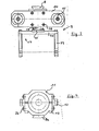
- Figur 3 eine Ansicht der Absturzsicherung in Pfeilrichtung III der Fig. 2,
- Figur 4 eine Aufsicht einer Manschette zum Halten der Vorrichtung in Pfeilrichtung IV der Fig. 2,
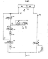
- Figur 5 eine Schaltungsanordnung zur Steuerung der Absturzsicherung.
- Die Fig. 1 zeigt den Teilbereich eines zur Dampferzeugung insbesondere in Kernkraftwerken vorgesehenen Wärmetauschers 1. Eine zur Einleitung bzw. Abführung des Primärkühlmittels vorgesehene Kammer 2 wird durch einen halbkugelförmigen Boden 3 und einen Rohrboden 4, in den eine Vielzahl von Rohren 5 enden, begrenzt. Zur Gewährleistung einer übersichtlichen Darstellung sind nur wenige der ca. 4000 im Rohrboden endenden Rohre angedeutet. Zur Vermeidung einer Strahlengefährdung müssen Reparatur- oder Inspektionseinrichtungen möglichst fernbedient durch ein Mannloch 6 in die Kammer 2 eingebracht und dort gehandhabt werden. Dies trifft auch für eine Vorrichtung 7 zum Ausziehen von Rohren 5 aus dem Rohrboden 4 zu. Ein bereits in der Kammer 2 befindlicher mit 35 angedeuteter Manipulator greift über eine Prismenführung 8, deren ineinander greifende Teile einerseits mit der Absturzsicherung 9 verschraubt und andererseits mit dem Manipulator 35 verbunden sind, eine in der Figur 2 in einem größeren Maßstab dargestellte Absturzsicherung 9 und bringt sie derart relativ zum Rohrboden in Position, daß zwei an einer Halteplatte 14 befestigte Spreizfinger 15 in Rohre 5 eingreifen und dort arretiert werden. Die Halteplatte 14 trägt weiterhin über Schrauben 38 (Fig. 3) einen kolbenstangenlosen Zylinder 16, von dessen Kolben 19 eine aus zwei Holmen 39 und einer Verbindungslasche 40 bestehende Konsole 17 auskragt. Die Konsole 17 ist über ihre Verbindungslasche 40 mit einer Anschlagplatte 41 des Kolbens 19 verschraubt. Einem als Hohlkolbenzylinder ausgebildeten hydraulichen Zylinder 10 der Vorrichtung 7 ist eine insbesondere in der Fig. 4 dargestellter Manschette 11 zugeordnet, die neben einer Prismenführung 8a zwei Abstützelemente 12 aufweist. Über zwei Schrauben 13 sind die zwei Hälften der Manschette 11 relativ zueinander bewegbar und können eine zuverlässige Klemmverbindung mit der Vorrichtung 7 eingehen. Nachdem die Klemmverbindung hergestellt ist werden mit Hilfe der Schrauben 36 die Abstützelemente 12 derart mit der Manschette 11 verbunden, daß ein Abstützelement von beiden Hälften der Manschette getragen wird. Die Durchtrittsöffnungen für die Schrauben 36 sind als Langlöcher ausgebildet, so daß eine Justierung der Abstützelemente 12 möglich ist. Durch Angreifen an der Prismenführung 8a übergibt der Manipulator 35 die Vorrichtung 7 an die Absturzsicherung 9. Sobald die Vorrichtung 7 über die keilförmig ausgebildeten Abstützelemente 12 in ebenso ausgebildete Aussparungen 18 der Konsole 17 eingehängt ist, ist die Aufgabe des Manipulators abgeschlossen. Aus Gründen der besseren Übersicht ist in der Fig. 2 die Vorrichtung 7 während ihrer Absenkbewegung in Pfeilrichtung 37, also vor dem Aufsetzen der keilförmig ausgebildeten Abstützelemente 12 in den keilförmig ausgebildeten Aussparungen 18 der Konsole 17 dargestellt. Der parallel zur Vorrichtung 7 angeordnete kolbenstangenlose Zylinder 16 wird nunmehr so weit in Richtung Rohrboden 4 verfahren, bis die Ziehkralle 34 der Vorrichtung 7 in ihre Arbeitsposition gelangt ist. Während der Bewegung der Vorrichtung 7 in und aus ihrer Ziehposition als auch während des eigentlichen Ziehvorganges ist die ca. 20 kg schwere Vorrichtung 7 stets gegen ein Abstürzen gesichert.
- Eine Schaltungsanordnung zur Steuerung des kolbenstangenlosen Zylinders 16 der Absturzsicherung 9 wird anhand der Figur 5 beschrieben. Der Kolben 19 des Zylinders 16 trennt einen mit einem Steuerstrang 20 verbundenen unteren Zylinderraum 21 von einem mit einem Steuerstrang 22 verbundenen oberen Zylinderraum 23. Diese Steuerstränge 20, 22 sind mit einem Luftanschluß 24 verbunden, der Luft mit einem Druck von ca. 6 bar einspeist. In Verbindung mit in diesen Steuersträngen eingebauten Mehrwegeventilen 25, 26 und Drosselventilen 27, 28 erlauben diese Steuerstränge ein Bewegen des Kolbens 19 und damit der über die Konsole 17 von dem Kolben 19 getragenen Vorrichtung 7 in vertikaler Richtung. Diese Bewegung ist zum Zwecke des Heranfahrens der Vorrichtung 7 in ihre bzw. des Wegfahrens derselben aus ihrer Ziehposition erforderlich.
- Während des Ziehvorganges dient der kolbenstangenlose Zylinder 16 als Absturzsicherung für die ca. 20 kg schwere Vorrichtung 7. Dazu wird dem unteren Zylinderraum 21 ein Nebenstrang 29 zugeschaltet. Bei entsprechender Stellung des Mehrwegeventils 25 und bei Offenstellung der dem Nebenstrang 29 zugeordneten Mehrwegeventile 30, 31 gelangt von der Luftquelle 24 Luft mit einem Druck von 6 bar in den Nebenstrang 29. Ein in dem Nebenstrang eingebautes Drosselventil 32 reduziert den Druck soweit, daß er eine Gleichgewichtskraft zu dem Eigengewicht der Vorrichtung 7 darstellt. Bei der Ziehbewegung der Vorrichtung 7 wird der Kolben 19 zwangsläufig nach unten bewegt. Damit sich im unteren Zylinderraum 21 kein Kompressionsdruch aufbauen kann, was letztendlich einer Übertragung der Ziehkraft auf die Spreizfinger-Befestigung des Zylinders 16 bedeuten würde ist oberhalb des Drosselventils 32 ein Druckschaltventil 33 an den Nebenstrang 29 angeschlossen. Steigt der Kompressionsdruck im unteren Zylinderraum 21 über den als Gleichgewichtskraft mit Hilfe des Drosselventils 32 eingestellten Druck, so schaltet das Druckschaltventil 33 und läßt den Überdruck ab. Während des gesamten Ziehvorganges herrscht also in dem unteren Zylinderraum 21 stets nur ein das Eigengewicht der Vorrichtung 7 kompensierender Druck. Dieser Druck wird auch bei einem unerwünschten Lösen der Ziehkralle 34 aus einem Rohr 5 aufrechterhalten. Die Vorrichtung 7 wird somit in jeder Betriebsphase zuverlässig gegen einen Absturz gesichert ohne daß auf die Absturzsicherung 9 selbst jeweils eine größere Kraft, als sie das Eigengewicht der Vorrichtung 7 darstellt, einwirkt.
-
- 1 Wärmetauscher
- 2 Kammer
- 3 Boden
- 4 Rohrboden
- 5 Rohr
- 6 Mannloch
- 7 Vorrichtung
- 8,8a Prismenführung
- 9 Absturzsicherung
- 10 Hydraulikzylinder
- 11 Manschette
- 12 Abstützelemente
- 13,36,38 Schrauben
- 14 Halteplatte
- 15 Spreizfinger
- 16 kolbenstangenloser Zylinder
- 17 Konsole
- 18 Aussparungen
- 19 Kolben
- 20,22 Steuerstrang
- 21 unterer Zylinderraum
- 23 oberer Zylinderraum
- 24 Luftanschluß
- 25,26,30,31 Mehrwegeventil
- 27,28,32 Drosselventil
- 29 Nebenstrang
- 33 Druckschaltventil
- 34 Ziehkralle
- 35 Manipulator
- 37 Pfeilrichtung
- 39 Holmen
- 40 Verbindungslasche
- 41 Anschlagplatte
Claims (5)
Applications Claiming Priority (2)
| Application Number | Priority Date | Filing Date | Title |
|---|---|---|---|
| DE19853521355 DE3521355A1 (de) | 1985-06-14 | 1985-06-14 | Absturzsicherung fuer eine vorrichtung zum ausziehen eines rohres aus einem rohrboden eines waermetauschers |
| DE3521355 | 1985-06-14 |
Publications (3)
| Publication Number | Publication Date |
|---|---|
| EP0204889A2 true EP0204889A2 (de) | 1986-12-17 |
| EP0204889A3 EP0204889A3 (en) | 1988-09-07 |
| EP0204889B1 EP0204889B1 (de) | 1990-10-17 |
Family
ID=6273268
Family Applications (1)
| Application Number | Title | Priority Date | Filing Date |
|---|---|---|---|
| EP86102316A Expired - Lifetime EP0204889B1 (de) | 1985-06-14 | 1986-02-22 | Absturzsicherung in Kombination mit einer Vorrichtung zum Ausziehen eines Rohres aus einem Rohrboden eines Wärmetauschers |
Country Status (5)
| Country | Link |
|---|---|
| US (1) | US4707912A (de) |
| EP (1) | EP0204889B1 (de) |
| JP (1) | JPS61288944A (de) |
| KR (1) | KR870000132A (de) |
| DE (2) | DE3521355A1 (de) |
Cited By (1)
| Publication number | Priority date | Publication date | Assignee | Title |
|---|---|---|---|---|
| WO1997017168A1 (de) * | 1995-11-07 | 1997-05-15 | Siemens Aktiengesellschaft | Verfahren und vorrichtung zum entsorgen eines radioaktiv kontaminierten dampferzeugers |
Families Citing this family (2)
| Publication number | Priority date | Publication date | Assignee | Title |
|---|---|---|---|---|
| DE3812351C1 (de) * | 1988-04-14 | 1990-01-11 | Abb Reaktor Gmbh, 6800 Mannheim, De | |
| DE4204657C1 (de) * | 1992-02-15 | 1993-08-05 | Abb Reaktor Gmbh, 6800 Mannheim, De |
Family Cites Families (12)
| Publication number | Priority date | Publication date | Assignee | Title |
|---|---|---|---|---|
| US1964023A (en) * | 1933-10-21 | 1934-06-26 | Armstrong Robert | Tube pulling device |
| US3785026A (en) * | 1972-06-07 | 1974-01-15 | Ohmstede Machine Works Inc | Method of dismantling tube bundles |
| US3836015A (en) * | 1973-03-29 | 1974-09-17 | B Travis | Tube bundle extractor |
| NL7307086A (de) * | 1973-05-21 | 1974-11-25 | ||
| US3979816A (en) * | 1975-01-17 | 1976-09-14 | Green Bernard S | Boiler tube extractor and method |
| US4095335A (en) * | 1977-01-12 | 1978-06-20 | Trouvay & Cauvin | Automatic tube puller |
| US4168782A (en) * | 1977-06-13 | 1979-09-25 | Westinghouse Electric Corp. | Remote access manipulator |
| NO150237C (no) * | 1977-07-11 | 1984-09-12 | Ici Ltd | Anordning til aa skyve en roerbunt ut av eller inn i mantelen til en varmeveksler |
| US4205939A (en) * | 1978-01-30 | 1980-06-03 | Westinghouse Electric Corp. | Apparatus for remotely repairing tubes in a steam generator |
| US4205940A (en) * | 1978-03-21 | 1980-06-03 | Westinghouse Electric Corp. | Apparatus for remotely repairing tubes in a steam generator |
| DE2912797A1 (de) * | 1979-03-30 | 1980-10-02 | Tu Ex Co Uwe Schneider | Vorrichtung zum ausziehen von rohren aus den rohrboeden von insbesondere grossen waermetauschanlagen |
| US4369569A (en) * | 1981-06-06 | 1983-01-25 | Armstrong & Sons | Tube-pulling apparatus |
-
1985
- 1985-06-14 DE DE19853521355 patent/DE3521355A1/de active Granted
-
1986
- 1986-02-22 EP EP86102316A patent/EP0204889B1/de not_active Expired - Lifetime
- 1986-02-22 DE DE8686102316T patent/DE3674950D1/de not_active Expired - Fee Related
- 1986-06-04 KR KR1019860004442A patent/KR870000132A/ko not_active Ceased
- 1986-06-12 US US06/873,370 patent/US4707912A/en not_active Expired - Fee Related
- 1986-06-13 JP JP61136344A patent/JPS61288944A/ja active Pending
Cited By (1)
| Publication number | Priority date | Publication date | Assignee | Title |
|---|---|---|---|---|
| WO1997017168A1 (de) * | 1995-11-07 | 1997-05-15 | Siemens Aktiengesellschaft | Verfahren und vorrichtung zum entsorgen eines radioaktiv kontaminierten dampferzeugers |
Also Published As
| Publication number | Publication date |
|---|---|
| DE3521355C2 (de) | 1989-06-29 |
| KR870000132A (ko) | 1987-02-16 |
| EP0204889A3 (en) | 1988-09-07 |
| DE3674950D1 (de) | 1990-11-22 |
| EP0204889B1 (de) | 1990-10-17 |
| JPS61288944A (ja) | 1986-12-19 |
| DE3521355A1 (de) | 1986-12-18 |
| US4707912A (en) | 1987-11-24 |
Similar Documents
| Publication | Publication Date | Title |
|---|---|---|
| DE2815705C2 (de) | Verfahren und Vorrichtung zum Zentrieren von Futterrohren | |
| DE2830233A1 (de) | Vorrichtung zum ein- und ausbau von waermetauscher-rohrbuendeln | |
| DE2304875C2 (de) | Vorrichtung zum Einblasen von Heisswind in einen Schachtofen, insbesondere Hochofen | |
| DE3217169C2 (de) | Falzmesserzylinder | |
| DE3509177C1 (de) | Einrichtung zum Einbringen eines zylindrischen Koerpers,insbesondere einer Huelse,in ein Rohr eines Dampferzeugers | |
| EP0693330A1 (de) | Verfahren und Vorrichtung zum Biegen von Rohren | |
| EP0204889B1 (de) | Absturzsicherung in Kombination mit einer Vorrichtung zum Ausziehen eines Rohres aus einem Rohrboden eines Wärmetauschers | |
| DE10235577B4 (de) | Positionier- und Spannvorrichtung | |
| EP0132619B1 (de) | Axialkompensator | |
| DE3535942C2 (de) | ||
| DE4029996C2 (de) | ||
| DE2106050B2 (de) | Vorrichtung zur werksmontage von ueberhitzerbaugruppen | |
| DE2602313A1 (de) | Verfahren zum herausziehen eines langen rohrfoermigen bauteils aus einer in einer halterung angebrachten bohrung und vorrichtung zum ausueben des verfahrens | |
| DE2607212B2 (de) | Kern zur Bildung eines Hohlraumes in einer Gießform herzustellenden plattenartigen Bauelementen | |
| DE8902521U1 (de) | Vorrichtung zum Runddrücken von Rohren | |
| EP1116859B1 (de) | Werkzeug zum Zusammenfügen und/oder Trennen von Rohren | |
| DE2263572B2 (de) | Walzgerüst für Walzensätze mit unterschiedlichen Ballenlängen | |
| AT280739B (de) | Vorrichtung zum Stanzen von Löchern in die Wandung von Hohlkörpern beliebigen Querschnitts | |
| AT397939B (de) | Vorrichtung zum abziehen eines formgebenden ringes von einem falz an der stirnseite eines ringförmigen werkstückes aus beton, insbesondere eines schachtringes | |
| DE2643582C2 (de) | Vorrichtung zur Längenverstellung von Gerüsten, Stützen o.dgl | |
| DE2954086C2 (de) | ||
| DE2755733A1 (de) | Manipulator mit nachfolgesteuerung (master-slave-manipulator) | |
| DE3313461C1 (de) | Anlage zur druckdichten Befestigung eines Rohres in einem Rohrboden mit Hilfe einer Druckflüssigkeit | |
| EP0283484B1 (de) | Spreizangel für eine rohrziehmaschine | |
| DE2153007A1 (en) | Pipe welding clamping unit - esp for holding large thermoplastics pipes for welding in trenches |
Legal Events
| Date | Code | Title | Description |
|---|---|---|---|
| PUAI | Public reference made under article 153(3) epc to a published international application that has entered the european phase |
Free format text: ORIGINAL CODE: 0009012 |
|
| AK | Designated contracting states |
Kind code of ref document: A2 Designated state(s): BE CH DE FR IT LI NL SE |
|
| PUAL | Search report despatched |
Free format text: ORIGINAL CODE: 0009013 |
|
| AK | Designated contracting states |
Kind code of ref document: A3 Designated state(s): BE CH DE FR IT LI NL SE |
|
| 17P | Request for examination filed |
Effective date: 19880926 |
|
| RAP1 | Party data changed (applicant data changed or rights of an application transferred) |
Owner name: ABB REAKTOR GMBH |
|
| 17Q | First examination report despatched |
Effective date: 19891026 |
|
| GRAA | (expected) grant |
Free format text: ORIGINAL CODE: 0009210 |
|
| ITF | It: translation for a ep patent filed | ||
| AK | Designated contracting states |
Kind code of ref document: B1 Designated state(s): BE CH DE FR IT LI NL SE |
|
| ET | Fr: translation filed | ||
| REF | Corresponds to: |
Ref document number: 3674950 Country of ref document: DE Date of ref document: 19901122 |
|
| PGFP | Annual fee paid to national office [announced via postgrant information from national office to epo] |
Ref country code: FR Payment date: 19910221 Year of fee payment: 6 |
|
| PGFP | Annual fee paid to national office [announced via postgrant information from national office to epo] |
Ref country code: SE Payment date: 19910222 Year of fee payment: 6 Ref country code: CH Payment date: 19910222 Year of fee payment: 6 |
|
| ITTA | It: last paid annual fee | ||
| PGFP | Annual fee paid to national office [announced via postgrant information from national office to epo] |
Ref country code: NL Payment date: 19910228 Year of fee payment: 6 |
|
| PGFP | Annual fee paid to national office [announced via postgrant information from national office to epo] |
Ref country code: BE Payment date: 19910313 Year of fee payment: 6 |
|
| PGFP | Annual fee paid to national office [announced via postgrant information from national office to epo] |
Ref country code: DE Payment date: 19910325 Year of fee payment: 6 |
|
| PLBE | No opposition filed within time limit |
Free format text: ORIGINAL CODE: 0009261 |
|
| STAA | Information on the status of an ep patent application or granted ep patent |
Free format text: STATUS: NO OPPOSITION FILED WITHIN TIME LIMIT |
|
| 26N | No opposition filed | ||
| PG25 | Lapsed in a contracting state [announced via postgrant information from national office to epo] |
Ref country code: SE Effective date: 19920223 |
|
| PG25 | Lapsed in a contracting state [announced via postgrant information from national office to epo] |
Ref country code: BE Effective date: 19920228 |
|
| PG25 | Lapsed in a contracting state [announced via postgrant information from national office to epo] |
Ref country code: LI Effective date: 19920229 Ref country code: CH Effective date: 19920229 |
|
| BERE | Be: lapsed |
Owner name: ABB REAKTOR G.M.B.H. Effective date: 19920228 |
|
| PG25 | Lapsed in a contracting state [announced via postgrant information from national office to epo] |
Ref country code: NL Effective date: 19920901 |
|
| NLV4 | Nl: lapsed or anulled due to non-payment of the annual fee | ||
| PG25 | Lapsed in a contracting state [announced via postgrant information from national office to epo] |
Ref country code: FR Effective date: 19921030 |
|
| REG | Reference to a national code |
Ref country code: CH Ref legal event code: PL |
|
| PG25 | Lapsed in a contracting state [announced via postgrant information from national office to epo] |
Ref country code: DE Effective date: 19921103 |
|
| REG | Reference to a national code |
Ref country code: FR Ref legal event code: ST |
|
| EUG | Se: european patent has lapsed |
Ref document number: 86102316.6 Effective date: 19920904 |
|
| PG25 | Lapsed in a contracting state [announced via postgrant information from national office to epo] |
Ref country code: IT Free format text: LAPSE BECAUSE OF NON-PAYMENT OF DUE FEES;WARNING: LAPSES OF ITALIAN PATENTS WITH EFFECTIVE DATE BEFORE 2007 MAY HAVE OCCURRED AT ANY TIME BEFORE 2007. THE CORRECT EFFECTIVE DATE MAY BE DIFFERENT FROM THE ONE RECORDED. Effective date: 20050222 |