EP0204098B1 - Dispositif de prise d'échantillons - Google Patents
Dispositif de prise d'échantillons Download PDFInfo
- Publication number
- EP0204098B1 EP0204098B1 EP86104520A EP86104520A EP0204098B1 EP 0204098 B1 EP0204098 B1 EP 0204098B1 EP 86104520 A EP86104520 A EP 86104520A EP 86104520 A EP86104520 A EP 86104520A EP 0204098 B1 EP0204098 B1 EP 0204098B1
- Authority
- EP
- European Patent Office
- Prior art keywords
- sampling device
- container
- agitator
- filter membrane
- outlet
- Prior art date
- Legal status (The legal status is an assumption and is not a legal conclusion. Google has not performed a legal analysis and makes no representation as to the accuracy of the status listed.)
- Expired - Lifetime
Links
- 238000005070 sampling Methods 0.000 title claims abstract description 41
- 239000012528 membrane Substances 0.000 claims abstract description 52
- 239000000706 filtrate Substances 0.000 claims abstract description 20
- 239000007788 liquid Substances 0.000 claims description 16
- 230000004044 response Effects 0.000 abstract description 5
- 239000000126 substance Substances 0.000 abstract description 4
- 238000003760 magnetic stirring Methods 0.000 abstract description 3
- 239000012530 fluid Substances 0.000 abstract description 2
- 230000003851 biochemical process Effects 0.000 abstract 1
- 238000010008 shearing Methods 0.000 abstract 1
- 210000004379 membrane Anatomy 0.000 description 19
- 238000003756 stirring Methods 0.000 description 15
- 238000000034 method Methods 0.000 description 8
- 230000002093 peripheral effect Effects 0.000 description 8
- 230000008569 process Effects 0.000 description 6
- 239000007787 solid Substances 0.000 description 6
- 238000007789 sealing Methods 0.000 description 5
- 230000003068 static effect Effects 0.000 description 3
- 230000015572 biosynthetic process Effects 0.000 description 2
- 230000008878 coupling Effects 0.000 description 2
- 238000010168 coupling process Methods 0.000 description 2
- 238000005859 coupling reaction Methods 0.000 description 2
- 238000006073 displacement reaction Methods 0.000 description 2
- 230000000694 effects Effects 0.000 description 2
- 238000011065 in-situ storage Methods 0.000 description 2
- 229920002521 macromolecule Polymers 0.000 description 2
- 238000002156 mixing Methods 0.000 description 2
- 238000000926 separation method Methods 0.000 description 2
- 206010010774 Constipation Diseases 0.000 description 1
- 102000004190 Enzymes Human genes 0.000 description 1
- 108090000790 Enzymes Proteins 0.000 description 1
- 229910000831 Steel Inorganic materials 0.000 description 1
- 239000004809 Teflon Substances 0.000 description 1
- 229920006362 Teflon® Polymers 0.000 description 1
- 230000009471 action Effects 0.000 description 1
- 230000033228 biological regulation Effects 0.000 description 1
- 230000008859 change Effects 0.000 description 1
- 238000004925 denaturation Methods 0.000 description 1
- 230000036425 denaturation Effects 0.000 description 1
- 238000001514 detection method Methods 0.000 description 1
- 238000011161 development Methods 0.000 description 1
- 230000018109 developmental process Effects 0.000 description 1
- 238000000502 dialysis Methods 0.000 description 1
- 238000005516 engineering process Methods 0.000 description 1
- 238000011156 evaluation Methods 0.000 description 1
- 238000000855 fermentation Methods 0.000 description 1
- 230000004151 fermentation Effects 0.000 description 1
- 238000001914 filtration Methods 0.000 description 1
- 238000003306 harvesting Methods 0.000 description 1
- 230000003993 interaction Effects 0.000 description 1
- 230000002452 interceptive effect Effects 0.000 description 1
- 238000012423 maintenance Methods 0.000 description 1
- 230000014759 maintenance of location Effects 0.000 description 1
- 239000000463 material Substances 0.000 description 1
- 238000009285 membrane fouling Methods 0.000 description 1
- 238000012544 monitoring process Methods 0.000 description 1
- 230000035699 permeability Effects 0.000 description 1
- 230000010287 polarization Effects 0.000 description 1
- -1 polytetrafluoroethylene Polymers 0.000 description 1
- 229920001343 polytetrafluoroethylene Polymers 0.000 description 1
- 239000004810 polytetrafluoroethylene Substances 0.000 description 1
- 238000002360 preparation method Methods 0.000 description 1
- 238000012545 processing Methods 0.000 description 1
- 239000000047 product Substances 0.000 description 1
- 102000004169 proteins and genes Human genes 0.000 description 1
- 108090000623 proteins and genes Proteins 0.000 description 1
- 238000005086 pumping Methods 0.000 description 1
- 230000000717 retained effect Effects 0.000 description 1
- 238000001179 sorption measurement Methods 0.000 description 1
- 229910001220 stainless steel Inorganic materials 0.000 description 1
- 239000010935 stainless steel Substances 0.000 description 1
- 239000010959 steel Substances 0.000 description 1
- 230000001954 sterilising effect Effects 0.000 description 1
- 238000004659 sterilization and disinfection Methods 0.000 description 1
Images


Classifications
-
- B—PERFORMING OPERATIONS; TRANSPORTING
- B01—PHYSICAL OR CHEMICAL PROCESSES OR APPARATUS IN GENERAL
- B01D—SEPARATION
- B01D65/00—Accessories or auxiliary operations, in general, for separation processes or apparatus using semi-permeable membranes
- B01D65/08—Prevention of membrane fouling or of concentration polarisation
-
- B—PERFORMING OPERATIONS; TRANSPORTING
- B01—PHYSICAL OR CHEMICAL PROCESSES OR APPARATUS IN GENERAL
- B01D—SEPARATION
- B01D29/00—Filters with filtering elements stationary during filtration, e.g. pressure or suction filters, not covered by groups B01D24/00 - B01D27/00; Filtering elements therefor
- B01D29/01—Filters with filtering elements stationary during filtration, e.g. pressure or suction filters, not covered by groups B01D24/00 - B01D27/00; Filtering elements therefor with flat filtering elements
- B01D29/05—Filters with filtering elements stationary during filtration, e.g. pressure or suction filters, not covered by groups B01D24/00 - B01D27/00; Filtering elements therefor with flat filtering elements supported
-
- B—PERFORMING OPERATIONS; TRANSPORTING
- B01—PHYSICAL OR CHEMICAL PROCESSES OR APPARATUS IN GENERAL
- B01D—SEPARATION
- B01D29/00—Filters with filtering elements stationary during filtration, e.g. pressure or suction filters, not covered by groups B01D24/00 - B01D27/00; Filtering elements therefor
- B01D29/01—Filters with filtering elements stationary during filtration, e.g. pressure or suction filters, not covered by groups B01D24/00 - B01D27/00; Filtering elements therefor with flat filtering elements
- B01D29/075—Filters with filtering elements stationary during filtration, e.g. pressure or suction filters, not covered by groups B01D24/00 - B01D27/00; Filtering elements therefor with flat filtering elements located in a closed housing and comprising scrapers or agitators on the cake side of the filtering elements, e.g. Nutsche- or Rosenmund-type filters for performing multiple step operations such as chemical reactions, filtering and cake treatment
-
- B—PERFORMING OPERATIONS; TRANSPORTING
- B01—PHYSICAL OR CHEMICAL PROCESSES OR APPARATUS IN GENERAL
- B01D—SEPARATION
- B01D29/00—Filters with filtering elements stationary during filtration, e.g. pressure or suction filters, not covered by groups B01D24/00 - B01D27/00; Filtering elements therefor
- B01D29/76—Handling the filter cake in the filter for purposes other than for regenerating
- B01D29/80—Handling the filter cake in the filter for purposes other than for regenerating for drying
- B01D29/84—Handling the filter cake in the filter for purposes other than for regenerating for drying by gases or by heating
-
- B—PERFORMING OPERATIONS; TRANSPORTING
- B01—PHYSICAL OR CHEMICAL PROCESSES OR APPARATUS IN GENERAL
- B01D—SEPARATION
- B01D29/00—Filters with filtering elements stationary during filtration, e.g. pressure or suction filters, not covered by groups B01D24/00 - B01D27/00; Filtering elements therefor
- B01D29/76—Handling the filter cake in the filter for purposes other than for regenerating
- B01D29/86—Retarding cake deposition on the filter during the filtration period, e.g. using stirrers
-
- B—PERFORMING OPERATIONS; TRANSPORTING
- B01—PHYSICAL OR CHEMICAL PROCESSES OR APPARATUS IN GENERAL
- B01D—SEPARATION
- B01D29/00—Filters with filtering elements stationary during filtration, e.g. pressure or suction filters, not covered by groups B01D24/00 - B01D27/00; Filtering elements therefor
- B01D29/88—Filters with filtering elements stationary during filtration, e.g. pressure or suction filters, not covered by groups B01D24/00 - B01D27/00; Filtering elements therefor having feed or discharge devices
- B01D29/885—Filters with filtering elements stationary during filtration, e.g. pressure or suction filters, not covered by groups B01D24/00 - B01D27/00; Filtering elements therefor having feed or discharge devices with internal recirculation through the filtering element
-
- B—PERFORMING OPERATIONS; TRANSPORTING
- B01—PHYSICAL OR CHEMICAL PROCESSES OR APPARATUS IN GENERAL
- B01D—SEPARATION
- B01D29/00—Filters with filtering elements stationary during filtration, e.g. pressure or suction filters, not covered by groups B01D24/00 - B01D27/00; Filtering elements therefor
- B01D29/88—Filters with filtering elements stationary during filtration, e.g. pressure or suction filters, not covered by groups B01D24/00 - B01D27/00; Filtering elements therefor having feed or discharge devices
- B01D29/90—Filters with filtering elements stationary during filtration, e.g. pressure or suction filters, not covered by groups B01D24/00 - B01D27/00; Filtering elements therefor having feed or discharge devices for feeding
- B01D29/908—Filters with filtering elements stationary during filtration, e.g. pressure or suction filters, not covered by groups B01D24/00 - B01D27/00; Filtering elements therefor having feed or discharge devices for feeding provoking a tangential stream
-
- B—PERFORMING OPERATIONS; TRANSPORTING
- B01—PHYSICAL OR CHEMICAL PROCESSES OR APPARATUS IN GENERAL
- B01D—SEPARATION
- B01D61/00—Processes of separation using semi-permeable membranes, e.g. dialysis, osmosis or ultrafiltration; Apparatus, accessories or auxiliary operations specially adapted therefor
- B01D61/14—Ultrafiltration; Microfiltration
- B01D61/18—Apparatus therefor
-
- B—PERFORMING OPERATIONS; TRANSPORTING
- B01—PHYSICAL OR CHEMICAL PROCESSES OR APPARATUS IN GENERAL
- B01D—SEPARATION
- B01D63/00—Apparatus in general for separation processes using semi-permeable membranes
- B01D63/08—Flat membrane modules
- B01D63/087—Single membrane modules
-
- G—PHYSICS
- G01—MEASURING; TESTING
- G01N—INVESTIGATING OR ANALYSING MATERIALS BY DETERMINING THEIR CHEMICAL OR PHYSICAL PROPERTIES
- G01N1/00—Sampling; Preparing specimens for investigation
- G01N1/02—Devices for withdrawing samples
- G01N1/10—Devices for withdrawing samples in the liquid or fluent state
-
- B—PERFORMING OPERATIONS; TRANSPORTING
- B01—PHYSICAL OR CHEMICAL PROCESSES OR APPARATUS IN GENERAL
- B01D—SEPARATION
- B01D2321/00—Details relating to membrane cleaning, regeneration, sterilization or to the prevention of fouling
- B01D2321/20—By influencing the flow
- B01D2321/2033—By influencing the flow dynamically
- B01D2321/2041—Mixers; Agitators
-
- B—PERFORMING OPERATIONS; TRANSPORTING
- B01—PHYSICAL OR CHEMICAL PROCESSES OR APPARATUS IN GENERAL
- B01D—SEPARATION
- B01D2321/00—Details relating to membrane cleaning, regeneration, sterilization or to the prevention of fouling
- B01D2321/20—By influencing the flow
- B01D2321/2066—Pulsated flow
Definitions
- the invention relates to a sampling device for taking filtered samples from liquids, comprising a container which has a rotatable stirrer above a filter membrane, an inlet opening above the filter membrane into the container and a filtrate outlet leading out of the container below the filter membrane.
- Stirring cells are known with a magnetic stirring rod (AMICON magnetic stirring cell) attached over a filter membrane.
- the filter membrane rests on a disc, which has profiles on its top for removing the filtrate.
- the liquid to be filtered is introduced into the container under pressure through an inlet in the container lid and is kept in motion by the magnetic stir bar above the filter membrane.
- the first two sub-steps are often associated with considerable difficulties if a fast time behavior is required.
- the known sampling devices generally allow only a batch sampling of dissolved or gaseous low molecular weight components.
- macromolecules e.g. Proteins and enzymes
- the existing systems are unsuitable because of signs of denaturation and uncontrollable occupancy or constipation problems.
- dialysis systems have the disadvantage of longer dead times because the concentration difference required for mass transport must be taken into account.
- By-pass systems with closed circuits are used in biotechnology, for example for continuous fermentation with cell mass retention for harvesting cells and processing organic products.
- the use of such techniques for continuous sampling is difficult because of the problem of membrane fouling due to adsorption and polarization effects.
- Other problems arise from the generally large dead volumes with correspondingly long response times and from the short downtimes.
- the invention has for its object to provide a sampling device of the type mentioned that enables continuous sampling with largely uniform permeability of the filter membrane.
- the inlet is arranged near the bottom and ends tangentially in the container in the same direction as the stirrer rotation, and that the container has an outlet in the upper end wall.
- the sampling device enables a constant exchange of the entire container volume at a rate that is much higher than the filtration rate.
- the liquid is introduced into the interior of the container with controlled swirling and the stirrer generates a constantly changing pressure alternating field above the filter membrane to keep the filter membrane free of residues.
- the filter membrane is constantly flushed through the tangential inlet with a high liquid rate and this effect is intensified by the stirrer running in sync with the liquid flow. This prevents the membrane from clogging with solids. The solids are rather from the Rinsed membrane and removed with the flowing liquid through the outlet from the container. In this way, with a long service life, there is an even filtrate yield and a short response time of the device or system.
- the outlet is preferably arranged on the side opposite the inlet. It lies lower than the outlet, so that the freshly supplied liquid first sweeps over the filter membrane and then rises to finally reach the outlet after repeated rotation over the filter membrane.
- the sampling device ensures optimum control of the formation of the cover layer on the filter membrane.
- a directed turbulence field is generated on the filter membrane by the interaction of the stirring bar rotating closely above the filter membrane in connection with the tangential inlet.
- the stirring bar is at such a distance from the filter membrane that no shear occurs at the filter membrane, so that overflow of the membrane and flow through the device are decoupled from one another.
- the decisive factor for the amount of filtrate is not the static operating pressure, but rather the dynamic alternating pressure generated by the stirrer. This makes it possible to freely select the static operating pressure within wide limits, and in particular to keep it very small.
- the bottom of the container has a groove leading from the center of the bottom to the filtrate outlet and that a disk provided with numerous holes is arranged directly on the bottom as a membrane carrier, on the underside of which there are grooves are provided, into which the holes open.
- the dead space volume is essentially determined by the volume of the grooves.
- the filtrate can flow quickly to the filtrate outlet after passing through the membrane. This allows liquid to be drained from all sides of the bottom in the shortest way to the filtrate outlet.
- the grooves expediently run radially and their inner ends are connected to a collecting space which is formed in the central region of the disk on its underside.
- the holes taper towards the circumference of the disc. This enables the filtrate to be drawn off evenly across the cross-section of the disk.
- the disk expediently has an oblique edge on its upper side, against which a sealing ring presses.
- the disc is flattened outwards.
- the sealing ring not only serves to seal the system to the outside, but also to fix the filter membrane on the edge area of the pane.
- the stirring bar has a cross-section tapering downwards and a tear-off edge at the lower end.
- the tear-off edge moves at a controlled distance at high speed (300 to 500 rpm) above the filter membrane and thereby creates the pressure alternating field with which the liquid is driven through the filter membrane.
- the tear-off edge is vertical and its cross section preferably forms an angle of approximately 60 °.
- the outlet is arranged at the highest point on the inside of the upper end wall of the container and this end wall has one in the central region towards the inside of the container protruding projection. This prevents air bubbles that occur in the process stream from bioreactors from interfering with the mixing action. The air bubbles rise in the container and are discharged through the outlet.
- a magnetic stirrer is preferably used as the stirrer, which has a stirring bar that is height-adjustable during rotation.
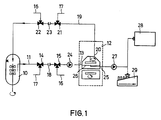
- a bioreactor 10 is provided, the outlet of which is connected via a line 11 to the inlet 13 of the sampling device 12.
- the line 11 contains two directional control valves 14 and 15, of which the directional control valve 15 is connected to a steam line 16.
- the directional control valve 14 is connected to a steam outlet line 17.
- a shut-off valve 18 is arranged between the directional control valves 14 and 15.
- two directional control valves 21 and 22 are provided in the line 19, which connects the outlet 20 of the sampling device 12 to the inlet of the bioreactor 10, between which a shut-off valve 23 is arranged.
- Sterilization steam can be supplied to the bioreactor 10 via the directional valve 22, while the outlet 20 of the sampling device can be connected to the steam outlet line 17 via the directional valve 21.
- a pump 24 is arranged between the directional control valve 15 and the inlet 13.
- shut-off valves 18 and 23 are closed, so that steam can be sent through the bioreactor 10 and / or through the sampling device 12.
- the lines 11 and 19 and the pump 24 are also sterilized.
- liquid is pumped from the bioreactor to the sampling device 12 via the pump 24.
- the liquid leaves the sampler through outlet 20 to be returned to bioreactor 10.
- solids are retained in the closed circuit between the bioreactor and the sampling device and the filtrate that has passed through the filter membrane 26 is fed via the filtrate outlet 25 and the pump 27 to the analyzer 28 and a fraction collector 29.
- the sampling device 12 shown in FIGS. 2 to 6 has a container made up of a lower part 30 and an upper part 31.
- the lower part 30 consists of a cylindrical trough with a flat bottom, in which one extends from the center to the filtrate outlet 25 radial groove 33 is arranged.
- the disc 34 which serves as a support for the filter membrane 26, lies flat on the bottom of the lower part 30.
- This disc 34 is provided with numerous holes 35 which are arranged along radial lines.
- On the underside of the disk 34 there are radial grooves 36 below the holes 35, one row of holes each opening into one of the grooves 36.
- the grooves 36 (FIG. 6) run out freely at their outer ends at the edge of the disk 34.
- the inner ends of the grooves 36 open into a collecting space 37 in the center of the disk 34.
- the collecting space 37 has the same depth as the grooves 36 and in it some of the holes 35 open in the central region of the disk. The diameters of the holes 35 decrease from the inside to the outside.
- FIGS. 4 and 5 show, the edge 34a of the disk 34 is flattened outwards.
- a sealing ring 137 presses the edge of the filter membrane 26 against the edge 34a of the disk 34.
- This sealing ring 37 also seals the gap between the peripheral wall 38 of the lower part 30 and the peripheral wall 39 of the upper part 31.
- the cylindrical peripheral wall 39 is inserted into the peripheral wall 38, and at the lower end it has a recess for receiving the sealing ring 137 which is delimited inward by the axial web 40.
- the web 40 forms the extension of the inside of the peripheral wall 39 and it ends just above the filter membrane 26.
- the inlet 13 which opens tangentially into the interior of the container.
- “Tangential” here means that the direction of the channel which the inlet 13 forms does not point to the longitudinal axis of the housing and that the inflowing Liquid is introduced into the interior of the container at least approximately parallel to the peripheral wall 39 so that it circles along the peripheral wall.
- the inlet 13 is in the lower half of the container.
- the end wall 40 has a projection 40a projecting into the interior of the container in the central region. Air bubbles that are introduced into the container rise into the annular space surrounding the projection 40 a and are discharged through the outlet 20.
- the stirrer 41 which coaxially plunges into the interior of the container, consists of a horizontal stirring bar 42, which contains a magnet 43.
- the stirring bar 42 which extends almost over the entire diameter of the interior of the container, has a triangular cross section with the tip pointing downward. This tip forms the tear-off edge 44, which is arranged above the filter membrane 26.
- the angle at the tear-off edge 44 is 60 °.
- the stirring bar 42 which consists of polytetrafluoroethylene, is fastened with a clamp 45 to a vertical connection piece 46 which is mounted in the sleeve 47 so as to be freely rotatable.
- a tangential pin 48 fixed in the sleeve 47 protrudes with part of its circumference into an annular groove of the socket 46 in order to secure the socket against axial displacements.
- the stirring bar 42 is driven by a drive magnet 49, which is arranged in a drive unit below the container and which acts with its magnetic field on the magnet 43 contained in the stirring bar 42.
- the Sleeve 47 leads through a bore of the end wall 40 sealed with the seal 50 into the tubular extension 51 of the housing.
- the adjusting bolt 52 In the upper end of the sleeve 47 protrudes the adjusting bolt 52, which is adjustable with its external thread in an internal thread of the extension 51.
- the outer end of the bolt 53 is guided in a vertical guide slot 55 of the projection 51.
- the position of the bolt 53 shows the height at which the stirring bar 42 is located above the membrane 26.
- the adjusting bolt 52 is provided with a rotary knob 56 at its outer end.
- a lock nut 57 is screwed onto the external thread of the adjusting bolt 52 from the outside.
- the height of the stirring bar 52 above the membrane 26 can also be changed during the operation of the magnetic stirrer 41. This is important for on-line operation because it is sometimes necessary to change the height of the stirring bar without interrupting the continuous flow operation.
- the separation process can be adapted to any changes in the process fluid (e.g. solids content, viscosity) during operation.
- the upper housing part 31 is connected to the lower housing part 30 by screws 58 which pass through corresponding outer flanges of both housing parts are.
- a flat hold-down device (not shown) can be placed over the filter membrane 26 and prevents the filter membrane from bulging.
- the dead volume below the membrane 26 is formed by the volume of the holes 35 and grooves 36 as well as the collecting space 37 and the groove 33. This dead volume is extremely small, e.g. 2 ml.
- the container and all parts in it are made of steam sterilizable material, such as steel or Teflon ® .
Landscapes
- Chemical & Material Sciences (AREA)
- Chemical Kinetics & Catalysis (AREA)
- Life Sciences & Earth Sciences (AREA)
- Water Supply & Treatment (AREA)
- Engineering & Computer Science (AREA)
- Analytical Chemistry (AREA)
- Biochemistry (AREA)
- General Health & Medical Sciences (AREA)
- General Physics & Mathematics (AREA)
- Immunology (AREA)
- Pathology (AREA)
- Physics & Mathematics (AREA)
- Hydrology & Water Resources (AREA)
- Health & Medical Sciences (AREA)
- Sampling And Sample Adjustment (AREA)
- Medicines Containing Antibodies Or Antigens For Use As Internal Diagnostic Agents (AREA)
- Saccharide Compounds (AREA)
- Medicines Containing Material From Animals Or Micro-Organisms (AREA)
- Measurement Of Radiation (AREA)
- Apparatus Associated With Microorganisms And Enzymes (AREA)
- Centrifugal Separators (AREA)
- Measuring Or Testing Involving Enzymes Or Micro-Organisms (AREA)
- Mechanical Treatment Of Semiconductor (AREA)
- Iron Core Of Rotating Electric Machines (AREA)
- Ultra Sonic Daignosis Equipment (AREA)
Claims (12)
- Dispositif de prise d'échantillons destiné au prélèvement d'échantillons filtrés à partir de liquides, comprenant un récipient (12) qui comporte au-dessus d'une membrane de filtration (26) un agitateur (41) rotatif, une ouverture d'entrée (13) débouchant dans le récipient (12) au-dessus de la membrane de filtration (26), et une ouverture de sortie de produit filtré (25) sortant du récipient (12) en dessous de la membrane de filtration (26),
caractérisé en ce que l'ouverture d'entrée (13) est disposée à proximité du fond et débouche tangentiellement dans le récipient (12) en étant orientée dans la direction du sens de rotation de l'agitateur, et en ce que le récipient (12) comporte une ouverture de sortie (20) dans la paroi frontale supérieure (40b). - Dispositif de prise d'échantillons selon la revendication 1, caractérisé en ce que l'ouverture de sortie (20) est disposée sur le côté opposé à celui où se situe l'ouverture d'entrée (13).
- Dispositif de prise d'échantillons selon la revendication 1 ou 2, caractérisé en ce que le fond du récipient (12) présente une rainure (33) conduisant du centre du fond à l'ouverture de sortie du produit filtré (25), et en ce qu'un disque (34) pourvu d'un grand nombre de trous (35) et faisant office de porte-membrane, est disposé directement sur le fond et est pourvu sur sa face inférieure, de rainures (36) dans lesquelles débouchent les trous (35).
- Dispositif de prise d'échantillons selon la revendication 3, caractérisé en ce que les rainures (36) s'étendent radialement et sont reliées à leurs extrémités intérieures, à une chambre de collecte (37).
- Dispositif de prise d'échantillons selon la revendication 3 ou 4, caractérisé en ce que les trous (35) se rétrécissent en direction de la périphérie du disque (34).
- Dispositif de prise d'échantillons selon l'une des revendications 1 à 5, caractérisé en ce que le disque (34) présente sur sa face supérieure, un bord chanfreiné (34a) contre lequel s'appuie une bague d'étanchéité (137).
- Dispositif de prise d'échantillons selon l'une des revendications 1 à 6, caractérisé en ce que le barreau d'agitation (42) présente une section droite se rétrécissant vers le bas, et présente à son extrémité inférieure une arête de décollement (44).
- Dispositif de prise d'échantillons selon la revendication 7, caractérisé en ce que l'arête de décollement (44) est en position verticale et en ce que sa section droite forme un angle d'environ 60°.
- Dispositif de prise d'échantillons selon l'une des revendications 1 à 8, caractérisé en ce que l'ouverture de sortie (20) est disposée au point le haut du côté intérieur de la paroi frontale supérieure (40b), et en ce que la paroi frontale présente dans la zone centrale, un bossage (40a) en saillie vers l'intérieur du récipient.
- Dispositif de prise d'échantillons selon l'une des revendications 1 à 9, caractérisé en ce que l'agitateur (41) est un agitateur magnétique entraîné par un aimant extérieur rotatif (49) et présentant un barreau d'agitation (42) susceptible d'être déplacé en hauteur au cours de la rotation.
- Dispositif de prise d'échantillons selon la revendication 10, caractérisé en ce qu'un tourillon (46) du barreau d'agitation (42) est disposé librement tournant dans une douille (47) montée sur la paroi frontale supérieure (40b) du récipient, de manière à pouvoir être déplacée en hauteur.
- Dispositif de prise d'échantillons selon la revendication 11, caractérisé en ce que la douille (47) comporte une broche (53) s'étendant transversalement en saillie latérale, et s'engageant dans une fente de guidage verticale (55) d'un appendice tubulaire creux (51) de la paroi frontale supérieure (40b), et en ce que l'extrémité intérieure de la broche (53) s'engage dans une gorge annulaire (54) d'une broche de réglage (52) s'engageant dans la douille (47) et pouvant être déplacée dans l'appendice creux (51) au moyen d'un filetage.
Priority Applications (1)
| Application Number | Priority Date | Filing Date | Title |
|---|---|---|---|
| AT86104520T ATE69304T1 (de) | 1985-06-07 | 1986-04-02 | Probeentnahmegeraet. |
Applications Claiming Priority (2)
| Application Number | Priority Date | Filing Date | Title |
|---|---|---|---|
| DE3520489 | 1985-06-07 | ||
| DE3520489A DE3520489C1 (de) | 1985-06-07 | 1985-06-07 | Probeentnahmegeraet |
Publications (3)
| Publication Number | Publication Date |
|---|---|
| EP0204098A2 EP0204098A2 (fr) | 1986-12-10 |
| EP0204098A3 EP0204098A3 (en) | 1989-05-10 |
| EP0204098B1 true EP0204098B1 (fr) | 1991-11-06 |
Family
ID=6272717
Family Applications (1)
| Application Number | Title | Priority Date | Filing Date |
|---|---|---|---|
| EP86104520A Expired - Lifetime EP0204098B1 (fr) | 1985-06-07 | 1986-04-02 | Dispositif de prise d'échantillons |
Country Status (8)
| Country | Link |
|---|---|
| US (1) | US4699013A (fr) |
| EP (1) | EP0204098B1 (fr) |
| JP (1) | JPS61284636A (fr) |
| AT (1) | ATE69304T1 (fr) |
| DE (2) | DE3520489C1 (fr) |
| DK (1) | DK264286A (fr) |
| FI (1) | FI862057A (fr) |
| NO (1) | NO168791C (fr) |
Families Citing this family (15)
| Publication number | Priority date | Publication date | Assignee | Title |
|---|---|---|---|---|
| US4762009A (en) * | 1987-03-04 | 1988-08-09 | Research Foundation Of State University Of New York | In-situ integrated suspended sediment stream sampler |
| FR2617286B1 (fr) * | 1987-06-26 | 1991-08-30 | Commissariat Energie Atomique | Dispositif de prelevement comportant une tete de prelevement sterilisable en position montee sur un bioreacteur |
| DE3924658A1 (de) * | 1989-07-26 | 1991-01-31 | Linde Ag | Verfahren zur filtration feststoffhaltiger fluessigkeiten |
| DE4117084A1 (de) * | 1991-05-25 | 1992-11-26 | Forschungszentrum Juelich Gmbh | Filtrationsgeraet |
| NL1006267C2 (nl) * | 1997-06-10 | 1998-12-14 | Chemferm Vof | Werkwijze voor het afscheiden van een vaste stof. |
| SE0102921D0 (sv) * | 2001-08-30 | 2001-08-30 | Astrazeneca Ab | Pharmaceutically useful compounds |
| US7141167B2 (en) | 2001-04-23 | 2006-11-28 | N F T Nanofiltertechnik Gmbh | Filter device |
| JP4245354B2 (ja) | 2001-05-31 | 2009-03-25 | ポール・コーポレーション | 流体処理用のウェル |
| US20040050802A1 (en) * | 2002-05-17 | 2004-03-18 | Banister John Patrick | Fluid bed filter-dryer apparatus |
| EP1967580B9 (fr) * | 2007-03-05 | 2012-04-04 | KRONES Aktiengesellschaft | Filtre à bière |
| EP2078556A3 (fr) * | 2008-01-14 | 2009-08-19 | PS Prozesstechnik GmbH | Procédé et dispositif destinés à la séparation de mélanges de produits |
| SE1150848A1 (sv) * | 2011-09-19 | 2013-03-20 | Förfarande och anordning för behandling av ett patientprov | |
| ES2608363T3 (es) * | 2014-06-17 | 2017-04-10 | Helmholtz-Zentrum Geesthacht Zentrum für Material- und Küstenforschung GmbH | Dispositivo para exponer cuerpos de ensayo en un líquido |
| IT201700089514A1 (it) * | 2017-08-03 | 2019-02-03 | Univ Degli Studi Di Sassari | Celle di permeazione |
| CN111235215A (zh) * | 2020-03-17 | 2020-06-05 | 南通鑫铭环保技术有限公司 | 应用于医院中的循环接触式空气微生物检测方法 |
Family Cites Families (8)
| Publication number | Priority date | Publication date | Assignee | Title |
|---|---|---|---|---|
| US2020529A (en) * | 1931-06-23 | 1935-11-12 | Thorsten Thorleif | Apparatus for sampling |
| DE1807230A1 (de) * | 1968-11-06 | 1970-05-27 | Boehringer Mannheim Gmbh | Verfahren und Vorrichtung zur kontinuierlichen Entnahme von klaren Fluessigkeitsproben |
| US3674153A (en) * | 1970-09-25 | 1972-07-04 | Beckman Instruments Inc | Bypass filter assembly and method of obtaining a filtered sample |
| US3801280A (en) * | 1971-11-11 | 1974-04-02 | Upjohn Co | Solubility-dissolution test apparatus and method |
| DE2526295B2 (de) * | 1975-06-12 | 1978-11-23 | Hoechst Ag, 6000 Frankfurt | Verfahren zur Herstellung einer Nutsche |
| NL7610352A (nl) * | 1976-09-17 | 1978-03-21 | Philips Nv | Inrichting voor het nemen van een vloeistof- monster. |
| US4417980A (en) * | 1980-06-18 | 1983-11-29 | Schenk Filterbau Gmbh | Filtration apparatus |
| US4317726A (en) * | 1981-02-12 | 1982-03-02 | The United States Of America As Represented By The Secretary Of The Army | Microbial filter assembly |
-
1985
- 1985-06-07 DE DE3520489A patent/DE3520489C1/de not_active Expired
-
1986
- 1986-04-02 AT AT86104520T patent/ATE69304T1/de not_active IP Right Cessation
- 1986-04-02 DE DE8686104520T patent/DE3682327D1/de not_active Expired - Fee Related
- 1986-04-02 EP EP86104520A patent/EP0204098B1/fr not_active Expired - Lifetime
- 1986-04-11 NO NO861427A patent/NO168791C/no unknown
- 1986-05-16 FI FI862057A patent/FI862057A/fi not_active IP Right Cessation
- 1986-05-29 US US06/868,352 patent/US4699013A/en not_active Expired - Fee Related
- 1986-06-04 DK DK264286A patent/DK264286A/da not_active Application Discontinuation
- 1986-06-06 JP JP61132603A patent/JPS61284636A/ja active Pending
Also Published As
| Publication number | Publication date |
|---|---|
| ATE69304T1 (de) | 1991-11-15 |
| JPS61284636A (ja) | 1986-12-15 |
| DK264286D0 (da) | 1986-06-04 |
| NO168791B (no) | 1991-12-23 |
| FI862057A0 (fi) | 1986-05-16 |
| US4699013A (en) | 1987-10-13 |
| EP0204098A3 (en) | 1989-05-10 |
| EP0204098A2 (fr) | 1986-12-10 |
| DE3520489C1 (de) | 1986-05-22 |
| DE3682327D1 (de) | 1991-12-12 |
| DK264286A (da) | 1986-12-08 |
| FI862057A (fi) | 1986-12-08 |
| NO861427L (no) | 1986-12-08 |
| NO168791C (no) | 1992-04-01 |
Similar Documents
| Publication | Publication Date | Title |
|---|---|---|
| EP0204098B1 (fr) | Dispositif de prise d'échantillons | |
| DE3486197T2 (de) | Filtrierverfahren und Vorrichtung. | |
| DE69919682T2 (de) | Rotierende scheibenfiltervorrichtung mit mitteln zur reduzierung der axialkräfte | |
| DE69804239T2 (de) | Verfahren und apparat zur durchmischung und abscheidung von partikel-material aus einer flüssigen probe | |
| DE69406523T2 (de) | Verfahren zur Zentrifugalkonzentrierung von Makromolekülen und Vorrichtung zur Durchführung des Verfahrens | |
| DE69304744T2 (de) | Dynamischer Filterabscheider | |
| EP1583597B9 (fr) | Dispositif de filtrage | |
| EP0123316B1 (fr) | Dispositif et procédé pour créer, ou libérer et séparer des substances ou des particules de matière liquide, plastique ou solide et utilisation du dispositif | |
| DE3542301A1 (de) | Verfahren und vorrichtung fuer die zirkulation einer fluessigen phase durch eine feste phase | |
| DE69404311T2 (de) | Verfahren und vorrichtung zur festphasenextraktion | |
| DE3606648A1 (de) | Durchlueftungsvorrichtung fuer fermentierungssysteme | |
| WO2003049841A1 (fr) | Dispositif destine a la dialyse simultanee d'une pluralite d'echantillons liquides | |
| WO1993023139A1 (fr) | Dispositif de filtrage | |
| DE68907938T2 (de) | Behälter für Zellkulturen. | |
| DE2924181C2 (de) | Fermentor zum Züchten von Mikroorganismen | |
| EP1126908A1 (fr) | Dispositif de dispersion | |
| EP0601140B1 (fr) | Dispositif visant a separer un flux d'echantillons d'analyse dans des eaux usees | |
| EP0965632B1 (fr) | Dispositif de fermentation en continu | |
| DE2333809C3 (de) | Verfahren zur Analyse von Flüssigkeitsproben für eine elektrochemisch meßbare Substanz und Vorrichtung zur Durchführung des Verfahrens | |
| EP0820804A1 (fr) | Procédé et appareil pour la préparation d'échantillons | |
| DE3519265A1 (de) | Reaktorgekoppelte filtrationsanlage mit automatischem probeneinlass zur aufbereitung und analyse von proben aus fermentationsprozessen | |
| EP0380487A1 (fr) | Procede et dispositif de concentration de solutions macromoleculaires. | |
| DE2314824A1 (de) | Geraet fuer die durchmischung von fluessigkeiten | |
| DE1557185C (de) | Vorrichtung zum innigen Inberührungbringen von gasförmigen und flüssigen Reaktionskomponenten für mikrobiologische Umsetzungen in einem Gärbehälter | |
| DE2017832A1 (de) | Brauverfahren |
Legal Events
| Date | Code | Title | Description |
|---|---|---|---|
| PUAI | Public reference made under article 153(3) epc to a published international application that has entered the european phase |
Free format text: ORIGINAL CODE: 0009012 |
|
| AK | Designated contracting states |
Kind code of ref document: A2 Designated state(s): AT BE CH DE FR GB IT LI LU NL SE |
|
| RAP1 | Party data changed (applicant data changed or rights of an application transferred) |
Owner name: GESELLSCHAFT FUER BIOTECHNOLOGISCHE FORSCHUNG MBH Owner name: B. BRAUN-SSC AG |
|
| RAP1 | Party data changed (applicant data changed or rights of an application transferred) |
Owner name: GESELLSCHAFT FUER BIOTECHNOLOGISCHE FORSCHUNG MBH Owner name: B. BRAUN-SSC AG |
|
| PUAL | Search report despatched |
Free format text: ORIGINAL CODE: 0009013 |
|
| AK | Designated contracting states |
Kind code of ref document: A3 Designated state(s): AT BE CH DE FR GB IT LI LU NL SE |
|
| 17P | Request for examination filed |
Effective date: 19890601 |
|
| 17Q | First examination report despatched |
Effective date: 19910116 |
|
| GRAA | (expected) grant |
Free format text: ORIGINAL CODE: 0009210 |
|
| AK | Designated contracting states |
Kind code of ref document: B1 Designated state(s): AT BE CH DE FR GB IT LI LU NL SE |
|
| REF | Corresponds to: |
Ref document number: 69304 Country of ref document: AT Date of ref document: 19911115 Kind code of ref document: T |
|
| GBT | Gb: translation of ep patent filed (gb section 77(6)(a)/1977) | ||
| REF | Corresponds to: |
Ref document number: 3682327 Country of ref document: DE Date of ref document: 19911212 |
|
| ET | Fr: translation filed | ||
| ITF | It: translation for a ep patent filed | ||
| PGFP | Annual fee paid to national office [announced via postgrant information from national office to epo] |
Ref country code: LU Payment date: 19920408 Year of fee payment: 7 |
|
| PGFP | Annual fee paid to national office [announced via postgrant information from national office to epo] |
Ref country code: SE Payment date: 19920416 Year of fee payment: 7 |
|
| PGFP | Annual fee paid to national office [announced via postgrant information from national office to epo] |
Ref country code: BE Payment date: 19920506 Year of fee payment: 7 |
|
| RAP2 | Party data changed (patent owner data changed or rights of a patent transferred) |
Owner name: GESELLSCHAFT FUER BIOTECHNOLOGISCHE FORSCHUNG MBH Owner name: B. BRAUN HOLDING AG |
|
| PLBE | No opposition filed within time limit |
Free format text: ORIGINAL CODE: 0009261 |
|
| STAA | Information on the status of an ep patent application or granted ep patent |
Free format text: STATUS: NO OPPOSITION FILED WITHIN TIME LIMIT |
|
| 26N | No opposition filed | ||
| EPTA | Lu: last paid annual fee | ||
| PG25 | Lapsed in a contracting state [announced via postgrant information from national office to epo] |
Ref country code: LU Free format text: LAPSE BECAUSE OF NON-PAYMENT OF DUE FEES Effective date: 19930402 |
|
| PG25 | Lapsed in a contracting state [announced via postgrant information from national office to epo] |
Ref country code: SE Effective date: 19930403 |
|
| PG25 | Lapsed in a contracting state [announced via postgrant information from national office to epo] |
Ref country code: BE Effective date: 19930430 |
|
| NLT1 | Nl: modifications of names registered in virtue of documents presented to the patent office pursuant to art. 16 a, paragraph 1 |
Owner name: B. BRAUN HOLDING AG TE EMMENBRUECKE, ZWITSERLAND E |
|
| BERE | Be: lapsed |
Owner name: G.- FUR BIOTECHNOLOGISCHE FORSCHUNG M.B.H. GBF Effective date: 19930430 Owner name: B. BRAUN HOLDING A.G. Effective date: 19930430 |
|
| EUG | Se: european patent has lapsed |
Ref document number: 86104520.1 Effective date: 19931110 |
|
| PGFP | Annual fee paid to national office [announced via postgrant information from national office to epo] |
Ref country code: GB Payment date: 19980316 Year of fee payment: 13 |
|
| PGFP | Annual fee paid to national office [announced via postgrant information from national office to epo] |
Ref country code: FR Payment date: 19980417 Year of fee payment: 13 |
|
| PGFP | Annual fee paid to national office [announced via postgrant information from national office to epo] |
Ref country code: AT Payment date: 19980423 Year of fee payment: 13 |
|
| PGFP | Annual fee paid to national office [announced via postgrant information from national office to epo] |
Ref country code: CH Payment date: 19980424 Year of fee payment: 13 |
|
| PGFP | Annual fee paid to national office [announced via postgrant information from national office to epo] |
Ref country code: NL Payment date: 19980428 Year of fee payment: 13 |
|
| PGFP | Annual fee paid to national office [announced via postgrant information from national office to epo] |
Ref country code: DE Payment date: 19980528 Year of fee payment: 13 |
|
| PG25 | Lapsed in a contracting state [announced via postgrant information from national office to epo] |
Ref country code: GB Free format text: LAPSE BECAUSE OF NON-PAYMENT OF DUE FEES Effective date: 19990402 Ref country code: AT Free format text: LAPSE BECAUSE OF NON-PAYMENT OF DUE FEES Effective date: 19990402 |
|
| PG25 | Lapsed in a contracting state [announced via postgrant information from national office to epo] |
Ref country code: LI Free format text: LAPSE BECAUSE OF NON-PAYMENT OF DUE FEES Effective date: 19990430 Ref country code: CH Free format text: LAPSE BECAUSE OF NON-PAYMENT OF DUE FEES Effective date: 19990430 |
|
| PG25 | Lapsed in a contracting state [announced via postgrant information from national office to epo] |
Ref country code: NL Free format text: LAPSE BECAUSE OF NON-PAYMENT OF DUE FEES Effective date: 19991101 |
|
| GBPC | Gb: european patent ceased through non-payment of renewal fee |
Effective date: 19990402 |
|
| REG | Reference to a national code |
Ref country code: CH Ref legal event code: PL |
|
| PG25 | Lapsed in a contracting state [announced via postgrant information from national office to epo] |
Ref country code: FR Free format text: LAPSE BECAUSE OF NON-PAYMENT OF DUE FEES Effective date: 19991231 |
|
| NLV4 | Nl: lapsed or anulled due to non-payment of the annual fee |
Effective date: 19991101 |
|
| REG | Reference to a national code |
Ref country code: FR Ref legal event code: ST |
|
| PG25 | Lapsed in a contracting state [announced via postgrant information from national office to epo] |
Ref country code: DE Free format text: LAPSE BECAUSE OF NON-PAYMENT OF DUE FEES Effective date: 20000201 |
|
| PG25 | Lapsed in a contracting state [announced via postgrant information from national office to epo] |
Ref country code: IT Free format text: LAPSE BECAUSE OF NON-PAYMENT OF DUE FEES;WARNING: LAPSES OF ITALIAN PATENTS WITH EFFECTIVE DATE BEFORE 2007 MAY HAVE OCCURRED AT ANY TIME BEFORE 2007. THE CORRECT EFFECTIVE DATE MAY BE DIFFERENT FROM THE ONE RECORDED. Effective date: 20050402 |