EP0201129B1 - Methode zur Herstellung eines Teils einer elektrischen Maschine - Google Patents
Methode zur Herstellung eines Teils einer elektrischen Maschine Download PDFInfo
- Publication number
- EP0201129B1 EP0201129B1 EP86200731A EP86200731A EP0201129B1 EP 0201129 B1 EP0201129 B1 EP 0201129B1 EP 86200731 A EP86200731 A EP 86200731A EP 86200731 A EP86200731 A EP 86200731A EP 0201129 B1 EP0201129 B1 EP 0201129B1
- Authority
- EP
- European Patent Office
- Prior art keywords
- connection element
- soft
- solder layer
- connection
- coil
- Prior art date
- Legal status (The legal status is an assumption and is not a legal conclusion. Google has not performed a legal analysis and makes no representation as to the accuracy of the status listed.)
- Expired
Links
- 238000004519 manufacturing process Methods 0.000 title claims description 6
- 229910000679 solder Inorganic materials 0.000 claims abstract description 32
- 238000000034 method Methods 0.000 claims description 14
- 238000005476 soldering Methods 0.000 claims description 10
- LQBJWKCYZGMFEV-UHFFFAOYSA-N lead tin Chemical compound [Sn].[Pb] LQBJWKCYZGMFEV-UHFFFAOYSA-N 0.000 claims description 3
- 238000004804 winding Methods 0.000 description 4
- 239000000463 material Substances 0.000 description 3
- 239000002184 metal Substances 0.000 description 3
- 239000004020 conductor Substances 0.000 description 2
- 229910000906 Bronze Inorganic materials 0.000 description 1
- OAICVXFJPJFONN-UHFFFAOYSA-N Phosphorus Chemical compound [P] OAICVXFJPJFONN-UHFFFAOYSA-N 0.000 description 1
- 239000010974 bronze Substances 0.000 description 1
- 239000011248 coating agent Substances 0.000 description 1
- 238000000576 coating method Methods 0.000 description 1
- 238000010276 construction Methods 0.000 description 1
- KUNSUQLRTQLHQQ-UHFFFAOYSA-N copper tin Chemical compound [Cu].[Sn] KUNSUQLRTQLHQQ-UHFFFAOYSA-N 0.000 description 1
- 238000005520 cutting process Methods 0.000 description 1
- 238000009413 insulation Methods 0.000 description 1
- 238000003466 welding Methods 0.000 description 1
Images
Classifications
-
- H—ELECTRICITY
- H01—ELECTRIC ELEMENTS
- H01R—ELECTRICALLY-CONDUCTIVE CONNECTIONS; STRUCTURAL ASSOCIATIONS OF A PLURALITY OF MUTUALLY-INSULATED ELECTRICAL CONNECTING ELEMENTS; COUPLING DEVICES; CURRENT COLLECTORS
- H01R39/00—Rotary current collectors, distributors or interrupters
- H01R39/02—Details for dynamo electric machines
- H01R39/32—Connections of conductor to commutator segment
-
- H—ELECTRICITY
- H01—ELECTRIC ELEMENTS
- H01R—ELECTRICALLY-CONDUCTIVE CONNECTIONS; STRUCTURAL ASSOCIATIONS OF A PLURALITY OF MUTUALLY-INSULATED ELECTRICAL CONNECTING ELEMENTS; COUPLING DEVICES; CURRENT COLLECTORS
- H01R4/00—Electrically-conductive connections between two or more conductive members in direct contact, i.e. touching one another; Means for effecting or maintaining such contact; Electrically-conductive connections having two or more spaced connecting locations for conductors and using contact members penetrating insulation
- H01R4/02—Soldered or welded connections
-
- H—ELECTRICITY
- H02—GENERATION; CONVERSION OR DISTRIBUTION OF ELECTRIC POWER
- H02K—DYNAMO-ELECTRIC MACHINES
- H02K13/00—Structural associations of current collectors with motors or generators, e.g. brush mounting plates or connections to windings; Disposition of current collectors in motors or generators; Arrangements for improving commutation
- H02K13/04—Connections between commutator segments and windings
Definitions
- the invention relates to a method of manufacturing an electrical machine part comprising a connection element and a coil having a coil end connected to the connection element, in which the coil end is wrapped around the connection element.
- a method of this kind is known from DE-A-30 44 663. According to the known method coil ends are wound round rectangular metal pins of a commutator, whereupon the coil ends are connected to the pins with the aid of a soldering bath.
- the fixing by means of soldering of two parts possessing different properties and different dimensions, such as said coil ends and said pins can cause problems, such as bad joints or wire fractures.
- An object of the invention is to provide a practical solution to these problems.
- the method according to the invention is characterized in that before the coil end is wrapped around the connection element, a soft-solded layer of at least 30 microns thickness is applied to the connection element and in that, after the coil end has been wrapped around the connection element provided with the soft-solder layer heat is applied to the soft-solder layer to melt said layer causing the coil end to sink at least partly into the soft-solder layer, after which the solft-solder layer is cooled causing a fixing of the coil end to the connection element.
- the fixing of the coil end to the connection element and of the connection element to a lug of a collector is preferably performed in a single soldering operation whereby a part of the soft-solder layer flows out over the lug.
- soft-solder layer a layer of a lead-tin compound is preferably applied.
- a laser can be used to apply heat to the soft-solder layer.
- the invention further relates to an electrical machine part obtained by the method according to the invention, in which the connection element is strip-shaped and is of at least substantially rectangular cross-section.
- the electrical machine part according to the invention is characterized in that the soft-solder layer surrounds the connection element as a sheath.
- the invention also relates to an electrical machine, in particular an electric motor, comprising a stator, a rotor which comprises coils having coil ends connected to connection elements and a collector having contact elements connected to the connection elements.
- connection elements of the known machine which elements serve for the electrical connection of the coil with other components of the machine, often have a larger cross-section and are made of a material having greater strength than the coil wire, which is thin relative to the connection elements. Because of this the fixing of the ends of the coil wire to the connection elements can give rise to problems, which is disadvantageous for example in automation of the process.
- An object of the invention is to provide a solution to these problems.
- the electric machine according to the invention in which the rotor is an electrical machine part in which the connection element is strip-shaped and is of at least substantially rectangular cross-section, the soft-solder layer surrounding the connection elements as a sheath,, or is obtainable with the method according to the invention, is characterized in that the external soft-layer on each connection element has a portion which has spread onto the contact element.
- a thin solder layer is known per se from GB-A-2 137 913 and is applied into an electrical connector for terminating and splicing high voltage power cables.
- That connector comprises a metallic tubular sleeve with an open end for receiving an electrical conductor.
- the inner wall of the sleeve is pretinned with an internal coating of solder having a thickness of a few thousands of an inch. After connection a cylindrical layer of solder is present in the cylindrical space bounded by said wall of the sleeve and the outer wall of the electrical conductor.
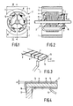
- Figures 1 and 2 show schematically an electric motor with a stator 1 and a rotor 2.
- Mounted on the shaft 3 of the rotor 2 is an insulating member 4 with a laminated core 5 and coils 6.
- the insulation member 4 is provided with axially directed connection elements 7 to which the ends 9 of the coil wire 8 are fixed.
- a collector 10 mounted on the shaft 3 is a collector 10 with contact elements 11, which contact elements are provided with lugs 12 that are in connection with the connection elements.7.
- connection element 7 is implemented as a metal strip of rectangular cross-section, which is a simple shape to manufacture and possesses a good plane surface for the lug 12.
- connection element 7 Since the connection element has to link up with other parts of the electric machine, as for example the said lug 12 of the collector 10 and is required to be resistant to mechanical loads, a connection element 7 will often be made of a material having a greater strength and a substantially larger cross-section than the coil wire 8.
- the mechanical load may be very considerable in particular when the connection elements 7 are mounted on a rotor as shown in the illustrated embodiment and are subject during operation of the machine to centrifugal forces.
- the fixing together of two parts possessing different strengths and different dimensions, such as the coil wire 8 and a connection element 7, can in general cause problems. In particular if the parts are fixed together by soldering or welding, there is a considerable risk of a bad joint or of wire fracture owing among other things to the great difference in the heat capacity of the parts.
- connection element with a soft-solder layer of at least approximately 30 kt thick.
- This soft-solder layer preferably of a lead-tin compound, surrounds like a sleeve the metal core 14 of rectangular cross-section, made for example of phosphor bronze.
- the usual thickness of a soft-solder layer for a soldered joint lies in the region of 5-10 ⁇ . Due to the relatively large thickness A ( Figure 4) of the soft-solder layer, being at least approximately 30 ⁇ , the edges of the connection element 7 are rounded. This prevents damage to the end 9 of a coil wire 8 through contact with a sharp edge of the connection element 7 when the ends of a few turns of wire are wound around the connection element.
- the fixing of the end 9 of the coil wire 8 to a connection element 7 and of the connection element to the lug 12 of the collector 10 can be performed in a single soldering operation whereby a part16 of the soft-solder layer 13 flows out over the lug 12.
- the construction in accordance with the invention lends itself particularly well for a soldering process using a laser, since in this way a really accurately directed and dosed quantity of heat can be supplied to the parts to be connected.
- the embodiment described in the foregoing is eminently suitable for an automated manufacturing process in which the winding of the coil, the winding of the ends of the coil wire around the connection elements and the soldering can be completely carried out by machines, since no exaggerated requirements need be imposed on the accuracy with which the turns of the end of the coil wire should be wound around the connection elements, the connections can be made in a single soldering process and the percentage of rejects is small.
Landscapes
- Engineering & Computer Science (AREA)
- Power Engineering (AREA)
- Manufacture Of Motors, Generators (AREA)
- Windings For Motors And Generators (AREA)
- Motor Or Generator Current Collectors (AREA)
- Apparatuses And Processes For Manufacturing Resistors (AREA)
- Insulation, Fastening Of Motor, Generator Windings (AREA)
Claims (7)
Priority Applications (1)
| Application Number | Priority Date | Filing Date | Title |
|---|---|---|---|
| AT86200731T ATE68638T1 (de) | 1985-05-03 | 1986-04-29 | Methode zur herstellung eines teils einer elektrischen maschine. |
Applications Claiming Priority (2)
| Application Number | Priority Date | Filing Date | Title |
|---|---|---|---|
| NL8501258 | 1985-05-03 | ||
| NL8501258A NL8501258A (nl) | 1985-05-03 | 1985-05-03 | Elektrische machine. |
Publications (3)
| Publication Number | Publication Date |
|---|---|
| EP0201129A1 EP0201129A1 (de) | 1986-11-12 |
| EP0201129B1 true EP0201129B1 (de) | 1991-10-16 |
| EP0201129B2 EP0201129B2 (de) | 1995-05-03 |
Family
ID=19845924
Family Applications (1)
| Application Number | Title | Priority Date | Filing Date |
|---|---|---|---|
| EP86200731A Expired - Lifetime EP0201129B2 (de) | 1985-05-03 | 1986-04-29 | Methode zur Herstellung eines Teils einer elektrischen Maschine |
Country Status (8)
| Country | Link |
|---|---|
| US (1) | US4691134A (de) |
| EP (1) | EP0201129B2 (de) |
| JP (1) | JP2537794B2 (de) |
| AT (1) | ATE68638T1 (de) |
| CA (1) | CA1265569A (de) |
| DE (1) | DE3681956D1 (de) |
| ES (1) | ES296782Y (de) |
| NL (1) | NL8501258A (de) |
Families Citing this family (4)
| Publication number | Priority date | Publication date | Assignee | Title |
|---|---|---|---|---|
| GB2220802A (en) * | 1988-07-06 | 1990-01-17 | Johnson Electric Ind Mfg | Connecting armature windings |
| EP0410211A1 (de) * | 1989-07-28 | 1991-01-30 | Siemens Aktiengesellschaft | Verfahren zur Herstellung einer elektrisch leitenden Verbindung zwischen Kupferlackdrähten und Anschlusselementen |
| EP0482707A3 (en) * | 1990-10-25 | 1993-11-18 | Philips Nv | Electric lamp |
| CN104972224B (zh) * | 2014-04-09 | 2016-09-14 | 四川安和精密电子电器有限公司 | 一种自动焊锡方法 |
Family Cites Families (11)
| Publication number | Priority date | Publication date | Assignee | Title |
|---|---|---|---|---|
| FR768194A (fr) * | 1933-02-18 | 1934-08-01 | Bosch Robert | Induit à collecteur, en particulier pour machines électriques exposées à de fortes trépidations |
| US2844749A (en) * | 1955-07-13 | 1958-07-22 | Gen Motors Corp | Dynamo electric machine commutator connection |
| US3274331A (en) * | 1960-10-12 | 1966-09-20 | Mark F Quigley | Electrical connector with pre-applied solder |
| GB1278246A (en) * | 1968-11-13 | 1972-06-21 | Lucas Industries Ltd | Method of connecting conductors to commutators in dynamo electric machines |
| US3665367A (en) * | 1969-08-20 | 1972-05-23 | Martin Marietta Corp | Side hole terminal |
| JPS50107462A (de) * | 1974-01-30 | 1975-08-23 | ||
| JPS5320561A (en) * | 1976-08-11 | 1978-02-24 | Hitachi Ltd | Method of connecting coated wires for electromagnetic coil |
| DE2929731A1 (de) * | 1979-07-23 | 1981-02-12 | Ringsdorff Werke Gmbh | Verfahren zum herstellen von lamellen fuer kommutatoren |
| DE3044663A1 (de) * | 1980-11-27 | 1982-06-24 | Blume & Redecker GmbH, 3000 Hannover | Anker fuer elektrische drehmaschinen |
| JPS6035780B2 (ja) * | 1981-08-19 | 1985-08-16 | 東邦金属株式会社 | マグネトロン用エンドハツト |
| IL71479A (en) * | 1983-04-11 | 1987-08-31 | Raychem Corp | Connectors for power distribution cables |
-
1985
- 1985-05-03 NL NL8501258A patent/NL8501258A/nl not_active Application Discontinuation
-
1986
- 1986-04-28 US US06/856,918 patent/US4691134A/en not_active Expired - Lifetime
- 1986-04-29 DE DE8686200731T patent/DE3681956D1/de not_active Expired - Lifetime
- 1986-04-29 EP EP86200731A patent/EP0201129B2/de not_active Expired - Lifetime
- 1986-04-29 AT AT86200731T patent/ATE68638T1/de not_active IP Right Cessation
- 1986-04-30 ES ES1986296782U patent/ES296782Y/es not_active Expired
- 1986-04-30 CA CA000508017A patent/CA1265569A/en not_active Expired
- 1986-04-30 JP JP61098398A patent/JP2537794B2/ja not_active Expired - Lifetime
Also Published As
| Publication number | Publication date |
|---|---|
| ES296782U (es) | 1988-10-16 |
| JPS61254044A (ja) | 1986-11-11 |
| JP2537794B2 (ja) | 1996-09-25 |
| EP0201129A1 (de) | 1986-11-12 |
| ES296782Y (es) | 1989-04-16 |
| CA1265569A (en) | 1990-02-06 |
| NL8501258A (nl) | 1986-12-01 |
| US4691134A (en) | 1987-09-01 |
| ATE68638T1 (de) | 1991-11-15 |
| EP0201129B2 (de) | 1995-05-03 |
| DE3681956D1 (de) | 1991-11-21 |
Similar Documents
| Publication | Publication Date | Title |
|---|---|---|
| KR100452706B1 (ko) | 차량용 교류발전기 | |
| US5264816A (en) | Electrical winding termination structure | |
| US3725707A (en) | Field sub-assembly for universal electric motors | |
| US3663914A (en) | Bobbin wound coil assembly and electrical terminals therefor | |
| KR100541334B1 (ko) | 회전전기 | |
| JP3578142B2 (ja) | 接続構造とその接続方法及びそれを用いた回転電機並びに交流発電機 | |
| EP0717488A2 (de) | Nulleiterverbindung für drahtgewickelten Stator | |
| US6160337A (en) | Electric motor with carbon track commutator | |
| EP0738024A2 (de) | Elektrischer Kompressor | |
| CN110474461B (zh) | 马达的定子及其制造方法 | |
| KR100516853B1 (ko) | 집속단자와도출코일의결합구조및그것을이용한소형회전전기와차량용교류발전기 | |
| US6853108B2 (en) | Rotor for small-sized motor and method of manufacturing same | |
| US5606208A (en) | Brushless motor having terminals for connecting winding ends to circuit board lands | |
| EP0201129B1 (de) | Methode zur Herstellung eines Teils einer elektrischen Maschine | |
| FI83579C (fi) | Hoegspaenningstransformator. | |
| JP2020503693A (ja) | サーマルプロテクタ | |
| JPS60190147A (ja) | 電機子巻線導体の製造方法 | |
| US5199160A (en) | Method of terminating electrical windings | |
| JPH0232861B2 (de) | ||
| EP0632934B1 (de) | Verfahren und Vorrichtung zur Herstellung eines Ankers | |
| JP2002262521A (ja) | 小型モータの回転子及びその製造方法 | |
| JP2003047213A (ja) | 絶縁電線の接合方法 | |
| JPH0590035A (ja) | 組立型チヨークコイル | |
| US3593052A (en) | Dynamoelectric machine commutator with coil end slats and method of making same | |
| JP3450557B2 (ja) | 端子付き電線及びそのはんだ付け方法 |
Legal Events
| Date | Code | Title | Description |
|---|---|---|---|
| PUAI | Public reference made under article 153(3) epc to a published international application that has entered the european phase |
Free format text: ORIGINAL CODE: 0009012 |
|
| AK | Designated contracting states |
Kind code of ref document: A1 Designated state(s): AT CH DE FR GB IT LI |
|
| PUAB | Information related to the publication of an a document modified or deleted |
Free format text: ORIGINAL CODE: 0009199EPPU |
|
| PUAF | Information related to the publication of a search report (a3 document) modified or deleted |
Free format text: ORIGINAL CODE: 0009199SEPU |
|
| R17D | Deferred search report published (corrected) |
Effective date: 19861217 |
|
| RA1 | Application published (corrected) |
Date of ref document: 19861217 Kind code of ref document: A1 |
|
| 17P | Request for examination filed |
Effective date: 19870504 |
|
| 17Q | First examination report despatched |
Effective date: 19890215 |
|
| GRAA | (expected) grant |
Free format text: ORIGINAL CODE: 0009210 |
|
| AK | Designated contracting states |
Kind code of ref document: B1 Designated state(s): AT CH DE FR GB IT LI |
|
| PG25 | Lapsed in a contracting state [announced via postgrant information from national office to epo] |
Ref country code: AT Effective date: 19911016 Ref country code: IT Free format text: LAPSE BECAUSE OF FAILURE TO SUBMIT A TRANSLATION OF THE DESCRIPTION OR TO PAY THE FEE WITHIN THE PRESCRIBED TIME-LIMIT;WARNING: LAPSES OF ITALIAN PATENTS WITH EFFECTIVE DATE BEFORE 2007 MAY HAVE OCCURRED AT ANY TIME BEFORE 2007. THE CORRECT EFFECTIVE DATE MAY BE DIFFERENT FROM THE ONE RECORDED. Effective date: 19911016 Ref country code: CH Effective date: 19911016 Ref country code: LI Effective date: 19911016 |
|
| REF | Corresponds to: |
Ref document number: 68638 Country of ref document: AT Date of ref document: 19911115 Kind code of ref document: T |
|
| REF | Corresponds to: |
Ref document number: 3681956 Country of ref document: DE Date of ref document: 19911121 |
|
| REG | Reference to a national code |
Ref country code: CH Ref legal event code: PL |
|
| ET | Fr: translation filed | ||
| PLBI | Opposition filed |
Free format text: ORIGINAL CODE: 0009260 |
|
| 26 | Opposition filed |
Opponent name: SIEMENS AKTIENGESELLSCHAFT, BERLIN UND MUENCHEN Effective date: 19920713 |
|
| PUAH | Patent maintained in amended form |
Free format text: ORIGINAL CODE: 0009272 |
|
| STAA | Information on the status of an ep patent application or granted ep patent |
Free format text: STATUS: PATENT MAINTAINED AS AMENDED |
|
| 27A | Patent maintained in amended form |
Effective date: 19950503 |
|
| AK | Designated contracting states |
Kind code of ref document: B2 Designated state(s): AT CH DE FR GB IT LI |
|
| REG | Reference to a national code |
Ref country code: FR Ref legal event code: CD |
|
| ET3 | Fr: translation filed ** decision concerning opposition | ||
| REG | Reference to a national code |
Ref country code: FR Ref legal event code: CD |
|
| PGFP | Annual fee paid to national office [announced via postgrant information from national office to epo] |
Ref country code: FR Payment date: 20010423 Year of fee payment: 16 |
|
| PGFP | Annual fee paid to national office [announced via postgrant information from national office to epo] |
Ref country code: GB Payment date: 20010430 Year of fee payment: 16 |
|
| PGFP | Annual fee paid to national office [announced via postgrant information from national office to epo] |
Ref country code: DE Payment date: 20010620 Year of fee payment: 16 |
|
| REG | Reference to a national code |
Ref country code: GB Ref legal event code: IF02 |
|
| PG25 | Lapsed in a contracting state [announced via postgrant information from national office to epo] |
Ref country code: GB Free format text: LAPSE BECAUSE OF NON-PAYMENT OF DUE FEES Effective date: 20020429 |
|
| PG25 | Lapsed in a contracting state [announced via postgrant information from national office to epo] |
Ref country code: DE Free format text: LAPSE BECAUSE OF NON-PAYMENT OF DUE FEES Effective date: 20021101 |
|
| GBPC | Gb: european patent ceased through non-payment of renewal fee |
Effective date: 20020429 |
|
| PG25 | Lapsed in a contracting state [announced via postgrant information from national office to epo] |
Ref country code: FR Free format text: LAPSE BECAUSE OF NON-PAYMENT OF DUE FEES Effective date: 20021231 |
|
| REG | Reference to a national code |
Ref country code: FR Ref legal event code: ST |