EP0200401A2 - Hauptzylinder - Google Patents
Hauptzylinder Download PDFInfo
- Publication number
- EP0200401A2 EP0200401A2 EP86302683A EP86302683A EP0200401A2 EP 0200401 A2 EP0200401 A2 EP 0200401A2 EP 86302683 A EP86302683 A EP 86302683A EP 86302683 A EP86302683 A EP 86302683A EP 0200401 A2 EP0200401 A2 EP 0200401A2
- Authority
- EP
- European Patent Office
- Prior art keywords
- flange
- master cylinder
- supporting wall
- cylinder according
- sealing
- Prior art date
- Legal status (The legal status is an assumption and is not a legal conclusion. Google has not performed a legal analysis and makes no representation as to the accuracy of the status listed.)
- Withdrawn
Links
Images
Classifications
-
- B—PERFORMING OPERATIONS; TRANSPORTING
- B60—VEHICLES IN GENERAL
- B60T—VEHICLE BRAKE CONTROL SYSTEMS OR PARTS THEREOF; BRAKE CONTROL SYSTEMS OR PARTS THEREOF, IN GENERAL; ARRANGEMENT OF BRAKING ELEMENTS ON VEHICLES IN GENERAL; PORTABLE DEVICES FOR PREVENTING UNWANTED MOVEMENT OF VEHICLES; VEHICLE MODIFICATIONS TO FACILITATE COOLING OF BRAKES
- B60T11/00—Transmitting braking action from initiating means to ultimate brake actuator without power assistance or drive or where such assistance or drive is irrelevant
- B60T11/10—Transmitting braking action from initiating means to ultimate brake actuator without power assistance or drive or where such assistance or drive is irrelevant transmitting by fluid means, e.g. hydraulic
- B60T11/16—Master control, e.g. master cylinders
- B60T11/236—Piston sealing arrangements
-
- B—PERFORMING OPERATIONS; TRANSPORTING
- B60—VEHICLES IN GENERAL
- B60T—VEHICLE BRAKE CONTROL SYSTEMS OR PARTS THEREOF; BRAKE CONTROL SYSTEMS OR PARTS THEREOF, IN GENERAL; ARRANGEMENT OF BRAKING ELEMENTS ON VEHICLES IN GENERAL; PORTABLE DEVICES FOR PREVENTING UNWANTED MOVEMENT OF VEHICLES; VEHICLE MODIFICATIONS TO FACILITATE COOLING OF BRAKES
- B60T11/00—Transmitting braking action from initiating means to ultimate brake actuator without power assistance or drive or where such assistance or drive is irrelevant
- B60T11/10—Transmitting braking action from initiating means to ultimate brake actuator without power assistance or drive or where such assistance or drive is irrelevant transmitting by fluid means, e.g. hydraulic
- B60T11/16—Master control, e.g. master cylinders
Definitions
- This invention is concerned with master cylinders aad their manufacture.
- the invention is directed to a master cylinder intended to be mounted on a bulkhead wall which separates a vehicle passenger compartment from the engine compartment of the vehicle.
- a brake master cylinder It is common e.g. on tractors, for a brake master cylinder to be mounted on a bulkhead wall, with a rear end portion of the master cylinder body protruding through an opening provided in the bulkhead wall.
- the body is generally cast from metal and formed with a mounting flange for engaging the bulkhead wall around the opening.
- To facilitate a flush fit between the flange and supporting wall it has been the practice hitherto to machine the rear face of the flange.
- holes have been machined in the flange to accommodate the threaded fasteners used to clamp the flange against the bulkhead wall, and a groove or the like has been machined around the body for seating engagement by a protective sealing boot which covers the rear end of the master cylinder to prevent ingress of dirt and moisture.
- a master cylinder comprising a body having a mounting flange, and holes in the flange for receiving fastening elements to secure the flange against a supporting wall, characterised in that the holes have the form of notches in the peripheral edge of the flange.
- the notches can be conveniently formed while casting the body, whereby a subsequent machining step to provide the notches or conventional bolt holes is eliminated.
- a master cylinder comprising a body formed as a casting and including a mounting flange, the flange having a rear face arranged to be secured against a supporting wall with an end portion of the body projecting into an opening in the wall, characterised in that the rear face of the flange is free of any machining treatment carried out to improve the surface smoothness, subsequent to the flange being formed, and the body carries sealing means adjacent the rear face of the flange to provide a fume seal between the body and the supporting wall.
- a master cylinder comprising a body including a mounting flange having a rear face arranged to be secured against a supporting wall with an end portion of the body projecting into an opening in the wall, an actuating rod protruding from the rear end of the body, and a sealing boot covering the rear end of the body and arranged to provide a seal between said projecting end portion and the actuating rod, characterised in that the boot includes integral sealing means at the forward end thereof, said sealing means being arranged to engage between the flange and the supporting wall to provide a fume seal therebetween and to secure the boot to the body.
- the seafing means serves to preclude any seepage of fumes into the vehicle passenger compartment between the flange and the supporting bulkhead wall against which it is mounted.
- a preferred master cylinder embodying the invention incorporates all of the aspects mentioned above, so that the mounting flange and the outer surface of the rearwardly projecting body portion need not be subjected to any machining steps.
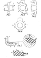
- the master cylinder body shown in Figures 1 and 2 is cast from metal and includes a mounting flange 1 adapted to be firmly mounted against a bulkhead wall separating engine and passenger compartments in a vehicle.
- a rear end portion 2 of the body projects beyond the flange and, in use, protrudes through an opening provided in the bulkhead wall 3, as may be seen in Figure 5.
- the flange is provided with a pair of diametrically opposed slots or notches 4 in its periphery, the notches being formed at the time of casting the body. Neither the notches, nor the rear mounting face of the flange 1 are subject to any machining treatment.
- the notches replace the conventional bolt holes and are adapted to receive the fastening elements (not shown) employed to clamp the flange against the bulkhead wall to fix the master cylinder in position.
- Alternative flange configurations with notches are illustrated in Figures 3 and 4. While a single pair of notches has been shown it will be understood that additional notches could be provided if desired.
- the master cylinder is equipped with sealing means to seal between the opening in the bulkhead and the rear portion of the master cylinder extending through the opening.
- the sealing means is conveniently integral with the forward end of a boot 6 which is arranged in known manner to provide a moisture and dirt barrier between the rear end of the master cylinder body and the actuating rod (not shown) which passes through this end of the body.
- the seal comprises a slightly thickened ring 7 having a series of parallel annular ribs 8 on its external surface. The ribs are designed to become compressed against the peripheral wall of the bulkhead opening to form a fume seal. In addition, these ribs serve to compensate for any slight misalignment between the opening and the master cylinder, which may arise through the use of the unmachined notches 4 to locate and fix the master cylinder in position.
- the rear end of the body is formed with external projections 9 (two as shown). Furthermore, the boot is provided with annular ribs 10 on its inner surface in the region where it adjoins the sealing ring 7, these ribs 10 being arranged to grip the master cylinder body to oppose rearward displacement of the ring 7.
- the modified embodiment of the sealing boot shown in Figure 7 includes an additional annular lip 11 which is adapted to be clamped between the rear face of the mounting flange and the bulkhead to enhance sealing and boot retention.
- annular ribs 8 may be omitted, as may the ribs 10.
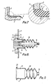
- the master cylinder body consists of a casting and includes a mounting flange 1 formed with diametrically opposed notches 4, e.g. as depicted in any of Figures 1 to 4.
- the notches pass through two bosses which project slightly from the rear face of the flange for abutment against the bulkhead wall 3 to which the master cylinder is secured by bolts (not shown).
- the bolts are inserted through the notches 4 and holes 14 provided in the wall 3 to register with the notches.
- the rear end portion 2 of the body projects through an opening 15 in the wall 3 and is fitted with a sealing boot 6.
- the boot includes a collar 16 which embraces the actuating rod 17 protruding through the rear end of the body, a bellows section 18, a sleeve 19 which surrounds the rear body portion 2, and a reversed sealing lip 20 at the forward end of the sleeve.
- the sleeve tapers towards the lip 20 (see Figure 9) for gripping the body portion 2 when the boot is fitted on the body.
- the free edge of the lip 20 is arranged to be pressed against the bulkhead wall 3 by the mounting flange 1 so that a fume seal is formed between the wall 3 and the master cylinder body.
- the bellows section 18 of the sealing boot ensures adequate flexibility in the axial direction for operation of the master cylinder to be unimpeded by the boot.
- the mounting flange is free of any machining treatment.
- each of the described master cylinders avoids completely the expense of machining the mounting flange during manufacture by the relatively simple and less expensive measure of utilising a modified boot seal.
- a circumferential groove is no longer necessary in the external surface of the body portion projecting rearwardly from the flange and by not having to machine the outside of the cast body there is secured an additional advantage of alleviating corrosion problems which have been encountered in the past due to the protective coating plated on to the casting being machined away.
Landscapes
- Engineering & Computer Science (AREA)
- Transportation (AREA)
- Mechanical Engineering (AREA)
- Transmission Of Braking Force In Braking Systems (AREA)
- Braking Systems And Boosters (AREA)
Applications Claiming Priority (2)
| Application Number | Priority Date | Filing Date | Title |
|---|---|---|---|
| GB858509951A GB8509951D0 (en) | 1985-04-18 | 1985-04-18 | Master cylinders |
| GB8509951 | 1985-04-18 |
Publications (2)
| Publication Number | Publication Date |
|---|---|
| EP0200401A2 true EP0200401A2 (de) | 1986-11-05 |
| EP0200401A3 EP0200401A3 (de) | 1987-08-05 |
Family
ID=10577850
Family Applications (1)
| Application Number | Title | Priority Date | Filing Date |
|---|---|---|---|
| EP86302683A Withdrawn EP0200401A3 (de) | 1985-04-18 | 1986-04-10 | Hauptzylinder |
Country Status (4)
| Country | Link |
|---|---|
| EP (1) | EP0200401A3 (de) |
| KR (1) | KR860008058A (de) |
| BR (1) | BR8601703A (de) |
| GB (1) | GB8509951D0 (de) |
Cited By (1)
| Publication number | Priority date | Publication date | Assignee | Title |
|---|---|---|---|---|
| WO2002020323A1 (de) * | 2000-09-05 | 2002-03-14 | Continental Teves Ag & Co. Ohg | Betätigungseinheit für eine elektrohydraulische bremsanlage |
Family Cites Families (5)
| Publication number | Priority date | Publication date | Assignee | Title |
|---|---|---|---|---|
| US3713292A (en) * | 1969-02-19 | 1973-01-30 | Midland Ross Corp | Hydraulic brake system |
| DE2125117B2 (de) * | 1971-05-21 | 1976-06-16 | Faltenbalg | |
| GB1584988A (en) * | 1977-08-04 | 1981-02-18 | Automotive Prod Co Ltd | Hydraulic acutator |
| DE3224168A1 (de) * | 1982-06-29 | 1983-12-29 | Alfred Teves Gmbh, 6000 Frankfurt | Druckguss-giessform fuer ein hauptbremszylindergehaeuse und mit dieser giessform hergestelltes druckguss-hauptbremszylindergehaeuse |
| JPS59100042A (ja) * | 1982-11-30 | 1984-06-09 | Aisin Seiki Co Ltd | 合成樹脂製のマスタシリンダ |
-
1985
- 1985-04-18 GB GB858509951A patent/GB8509951D0/en active Pending
-
1986
- 1986-04-10 EP EP86302683A patent/EP0200401A3/de not_active Withdrawn
- 1986-04-16 KR KR1019860002942A patent/KR860008058A/ko not_active Abandoned
- 1986-04-16 BR BR8601703A patent/BR8601703A/pt unknown
Cited By (2)
| Publication number | Priority date | Publication date | Assignee | Title |
|---|---|---|---|---|
| WO2002020323A1 (de) * | 2000-09-05 | 2002-03-14 | Continental Teves Ag & Co. Ohg | Betätigungseinheit für eine elektrohydraulische bremsanlage |
| US6851767B2 (en) | 2000-09-05 | 2005-02-08 | Continental Teves Ag & Co., Ohg | Actuator for an electrohydraulic braking system |
Also Published As
| Publication number | Publication date |
|---|---|
| BR8601703A (pt) | 1986-12-16 |
| GB8509951D0 (en) | 1985-05-30 |
| EP0200401A3 (de) | 1987-08-05 |
| KR860008058A (ko) | 1986-11-12 |
Similar Documents
| Publication | Publication Date | Title |
|---|---|---|
| US4932275A (en) | Arrangement for the fixation of a brake power booster | |
| ZA822291B (en) | Mudguard for motor vehicles, especially heavy-goods vehicles | |
| US5056412A (en) | Brake servomotor assembly mounted on a stationary wall of a vehicle | |
| GB2119455A (en) | Elastomeric sealing boot | |
| US4715648A (en) | Arrangement for increasing the body width at wheel housings of a vehicle | |
| EP0200401A2 (de) | Hauptzylinder | |
| GB2222859A (en) | Arrangement for fastening a brake booster | |
| US4170364A (en) | Shaft sealing system for a steam turbine | |
| GB2143784A (en) | Vehicle suspension shock absorber leg connection | |
| EP0510742A1 (de) | Schutzkappe für ein Teil einer Scheibenbremse | |
| US5896958A (en) | Drum brake with divided brake support plate | |
| JPH0356469Y2 (de) | ||
| JPH0730468Y2 (ja) | 車体のホイールハウス構造 | |
| JPH0235056Y2 (de) | ||
| KR200181181Y1 (ko) | 차량의 마스터실린더 장착구조 | |
| JPH07172235A (ja) | 車両用ランプの防水構造 | |
| KR200152178Y1 (ko) | 차량용 범퍼의 인서트볼트식 취부구조 | |
| KR200151281Y1 (ko) | 더스트 커버 겸용 abs 톤휠 | |
| JPS5931829Y2 (ja) | シ−ルド掘進機のシ−ル装置 | |
| JPS595618Y2 (ja) | エンジン支持装置 | |
| JPH11180354A (ja) | クローラ走行装置の駆動軸取付構造 | |
| JPH046378Y2 (de) | ||
| JPS6018674Y2 (ja) | 油圧ブレ−キ装置のブ−ツプロテクタ− | |
| JPH073118Y2 (ja) | 細径配管接続用コネクター | |
| JPS6146024Y2 (de) |
Legal Events
| Date | Code | Title | Description |
|---|---|---|---|
| PUAI | Public reference made under article 153(3) epc to a published international application that has entered the european phase |
Free format text: ORIGINAL CODE: 0009012 |
|
| AK | Designated contracting states |
Kind code of ref document: A2 Designated state(s): DE FR GB IT |
|
| PUAB | Information related to the publication of an a document modified or deleted |
Free format text: ORIGINAL CODE: 0009199EPPU |
|
| RA1 | Application published (corrected) |
Date of ref document: 19861210 Kind code of ref document: A2 |
|
| PUAL | Search report despatched |
Free format text: ORIGINAL CODE: 0009013 |
|
| AK | Designated contracting states |
Kind code of ref document: A3 Designated state(s): DE FR GB IT |
|
| 17P | Request for examination filed |
Effective date: 19870811 |
|
| 17Q | First examination report despatched |
Effective date: 19880810 |
|
| STAA | Information on the status of an ep patent application or granted ep patent |
Free format text: STATUS: THE APPLICATION IS DEEMED TO BE WITHDRAWN |
|
| 18D | Application deemed to be withdrawn |
Effective date: 19890221 |
|
| RIN1 | Information on inventor provided before grant (corrected) |
Inventor name: CAMPBELL, ROY Inventor name: TAYLOR, MICHAEL ANTHONY Inventor name: PRICE, ANTHONY GEORGE Inventor name: GWILLIAM, MALCOLM CLIVE |