EP0200162A2 - Procédé pour échanger automatiquement les capuchons d'électrodes de soudage et équipement pour l'application du procédé - Google Patents
Procédé pour échanger automatiquement les capuchons d'électrodes de soudage et équipement pour l'application du procédé Download PDFInfo
- Publication number
- EP0200162A2 EP0200162A2 EP86105665A EP86105665A EP0200162A2 EP 0200162 A2 EP0200162 A2 EP 0200162A2 EP 86105665 A EP86105665 A EP 86105665A EP 86105665 A EP86105665 A EP 86105665A EP 0200162 A2 EP0200162 A2 EP 0200162A2
- Authority
- EP
- European Patent Office
- Prior art keywords
- electrode
- welding
- magazine
- cap
- servomotor
- Prior art date
- Legal status (The legal status is an assumption and is not a legal conclusion. Google has not performed a legal analysis and makes no representation as to the accuracy of the status listed.)
- Granted
Links
Images
Classifications
-
- B—PERFORMING OPERATIONS; TRANSPORTING
- B23—MACHINE TOOLS; METAL-WORKING NOT OTHERWISE PROVIDED FOR
- B23K—SOLDERING OR UNSOLDERING; WELDING; CLADDING OR PLATING BY SOLDERING OR WELDING; CUTTING BY APPLYING HEAT LOCALLY, e.g. FLAME CUTTING; WORKING BY LASER BEAM
- B23K11/00—Resistance welding; Severing by resistance heating
- B23K11/30—Features relating to electrodes
- B23K11/3072—Devices for exchanging or removing electrodes or electrode tips
Definitions
- the invention relates to a method of the type specified in the preamble of the first claim and to an apparatus for performing the method.
- the generic method is known from DE-OS 33 23 038.
- the electrode shaft is clamped via a separate clamping device with a servomotor and then the electrode cap is clamped and rotated via a clamping device with a likewise separate servomotor, the pulling movement of the electrode cap being carried out simultaneously via a link guide.
- an electrode cap magazine with an anvil is provided in the immediate vicinity of this changing station. After the electrode cap has been removed, the electrode shaft is moved to this magazine, picks up an electrode cap there and strikes it on the anvil.
- the object of the present invention is to simplify the generic method. This object is achieved according to the invention by the characterizing features of the first claim.
- the solution is based on the knowledge that it is not necessary to remove the electrode cap by clamping the electrode shaft with a special holding device.
- the electrode shaft is usually attached to a welding robot. This can apply the necessary counterforce when turning and also the holding force during the trigger movement.
- the development of the method according to claim 2 has the advantage that when the electrode cap is changed automatically by a welding robot it is ensured that no attempt should be made to take up a new electrode cap if the old one has not been removed.
- the features of claim 4 describe a device which is particularly suitable for carrying out the method according to the invention.
- This arrangement makes it possible to carry out the entire electrode change with a single servomotor, since the holding and pulling forces can be applied by the welding robot itself or by the operator. This considerably simplifies the design effort compared to the previously known arrangement, which also reduces its susceptibility to faults.
- By using only a single servomotor it is also possible for the device to be located directly next to the welding robots can be set up because the space required for this is extremely small.
- the previously known device was less suitable for this, since due to the required space and the actually existing one, this could only be used occasionally.
- the training according to claim 5 describes a suitable training.
- Claims 9 and 10 describe a suitable control device.
- the control device is expediently arranged in spatial proximity to the receiving part so that the control process can be carried out immediately after the electrode cap has been removed.
- a limit switch has proven itself as a control device. This is approached by the electrode shaft in such a way that the switch is not actuated when the electrode cap is removed, whereas an error signal occurs when the electrode is not removed.
- This control device can also be used to determine whether a new electrode cap has been securely received. It is only necessary to reverse the travel path during the control process so that the limit switch must be operated in the opposite direction to determine that an electrode cap has been securely received.
- the advantage is achieved that the electrode shaft can be moved straight to the magazine to accommodate a new electrode cap there. This is a programming-technically simple process when using welding robots.
- a suitable separating device is described in claim 12. This achieves the advantage that it can be held securely during the cap holder, so that the electrode cap is in a clear position.
- Claim 13 describes a particularly simple embodiment of the magazine with a locking device. As a result, additional control devices unfold in order to transfer the electrode caps from the magazine into the separating device.
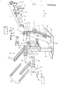
- 1 consists of a base plate 1, on which two columns 2 and 3 are attached.
- the column 3 While the column 3 is rigidly attached to the base plate 1, the column 2 is pivotally attached. For this purpose, it is connected to the base plate 1 via a hinge 2.1, for which purpose the hinge is attached in such a way that it can be tilted laterally.
- the column 3 is moved via a servomotor 2.2 fastened to the base plate 2.
- the clamping device 4 with its servomotor 5 is provided on the column 2.
- the servomotor is a hydraulically or pneumatically operated cylinder piston unit. This cylinder is rotatably attached to the column 2 by a fork 6.
- the free end of the piston rod is connected in an articulated manner to a connecting rod 7.
- This connecting rod 7 has two articulation points 8 and 9, which are arranged one above the other.
- an arm 10 is rotatably fastened, which has a sickle-shaped contour and is rotatably mounted in the clamping device 4.
- the clamping device 4 itself consists of the housing 11, in which the receiving part 12 is rotatably fastened.
- the receiving part 12 consists of a circular cylinder with a central bore 13.
- the central bore 13 serves to receive the electrode cap, not shown. It is serrated on its inner circumference in order to be able to hold the electrode against rotation.
- the arm 10 To attach the arm 10 to the receiving part 12, the latter is slotted on part of its outer circumference up to the receiving bore 13.
- the arm 10 engages in this slot. It is held by a pin 14, which is mounted in the receiving part 12.
- the arm 10 faces at its front with the receiving bore tion 13 cooperating end a circular segment-shaped section with a toothed circumferential surface so as to completely release the receiving bore 13 in the rest position.
- the receiving part 12 has at its lower, i.e. a region 15 facing the servomotor 5.
- control device 20 is attached to the column 3. It consists of two limit switches 21 and 22 arranged at a distance from the electrode shanks of the welding gun, which are equipped with actuating pins 23 and 24.
- a magazine 30 for new electrode caps is also provided on the column 3.
- the magazine 30 has a separating device 31 at its outlet. This consists of two jaws 32 and 33, which are kept at a distance via an energy accumulator 34. The distance between the jaws 32 and 33 is chosen such that an electrode cap can fall safely and easily into it.
- the electrode caps themselves are stacked in rails 35.
- the rails 35 are inclined at an angle to the horizontal, in such a way that the electrode caps located there can slide to the magazine outlet 36 under the influence of gravity.
- the magazine outlet 36 is in the rest position of the jaws 32 and 33 with their opening. All of the elements 31 - 36 of the magazine 30 described so far are present in duplicate.
- the magazine 30 is thus constructed as a double magazine in order to make the electrode cap holder as simple as possible for both welding gun shafts.
- the jaw pairs 32 and 33 are displaced perpendicularly to the magazine openings 36 up to a stop 38 by a single servomotor 37.
- the robot moves the welding gun in such a way that the other electrode shaft on the back of the holder bore 13 is. Now the column 2 is tilted back so that it envelops the electrode cap. In this case, the electrode cap that has already been removed in the receiving bore 13 is removed, tossed. The same removal process then takes place for the other electrode cap.
- the welding robot moves to the control device 20.
- the actuating pins 23 and 24 are at such a clear distance from one another that corresponds to the distance between the two welding gun shafts without an electrode cap. If both electrode caps are removed, the welding gun can be moved past the two actuating pins 23 and 24 without contact. If, however, one or both caps are not removed, one or both actuating pins are moved. This movement is detected by the corresponding limit switches 21 or 22 and leads to a backward movement of the welding robot towards the clamping device 4 in order to have the corresponding electrode cap removed again.
- the control device 20 is passed without actuating the two limit switches 21 and 22.
- the welding robot then moves on to the magazine 30. Due to the rest position of the two pairs of jaws 32 and 33, an electrode cap has slipped between each of the guide rails 35.
- the servomotor 37 is then actuated. As a result, the jaws 32 and, via the springs 34, the jaws 33 are displaced up to the stop 38. On the one hand, the magazine exits 36 are closed by this displacement movement, so that no electrode caps can slide down. On the other hand, when the jaws 33 hit the stop 38, the inserted electrode caps are clamped. In this position, the front electrode shaft is first immersed and then the rear one in the respective electrode cap. Then the servomotor 37 is relieved so that the jaw 31 can retreat due to the springs 34 and the electrode cap is released.
- the welding robot moves back to the control device 20 and passes it in the opposite direction. Due to the electrode caps picked up, the two actuating pins 23 and 24 are now deflected clockwise as they pass and actuate the associated limit switches 21 and 22. This signal means that both electrode caps are picked up. If a signal is missing, the control device of the welding robot knows that no electrode cap has been picked up on the side in question where the error signal originated. In this case, the welding robot is then moved back to the magazine so that the corresponding electrode shaft can accommodate a new electrode cap.
- the welding robot moves out of the area of the control device 20. Then the two welding gun boxes are pressed against each other. This ensures that the two pushed-on electrode caps are securely clamped on the electrode shafts. The robot is then ready for use again.
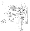
- FIG. 2 shows the electrode cap changing device according to the invention for welding robots with a picker. Since the picker consists of an electrode shaft with an attached electrode cap and is usually brought vertically into the welding position from above, the changing device shown in FIG. 2 is attached to a table, not shown in detail. It differs from the device shown in Fig. 1 only in that the clamping device 4 'is only accessible on one side and is not pivotable and that the magazine is formed only on one side and, accordingly, the control device consists of only one limit switch. The structure of the clamping device and its function is identical to the arrangement described in FIG. 1.
- the electrode is moved from the robot to the clamping device 4 ′ and there it lowers the electrode cap into the open receiving bore 13 ′. Then the clamping process described at the beginning takes place.
- the withdrawal movement which is simultaneously necessary while rotating the electrode cap is carried out by the robot itself by pulling the electrode out of the receiving bore 13 '.
- the control device 20 'and After the electrode shaft has been freed from the old electrode cap, has passed the control device 20 'and has received a new electrode cap from the magazine 30', it in turn travels to the control device 20 'and actuates the switching pin 23' there. Then he drives to the anvil 40 arranged between the electrode cap magazine 30 'and the control device 20'. Here, the electrode cap is pressed firmly onto the electrode shaft by repeated opening.
Landscapes
- Engineering & Computer Science (AREA)
- Mechanical Engineering (AREA)
- Resistance Welding (AREA)
Applications Claiming Priority (2)
| Application Number | Priority Date | Filing Date | Title |
|---|---|---|---|
| DE3515597 | 1985-04-30 | ||
| DE19853515597 DE3515597A1 (de) | 1985-04-30 | 1985-04-30 | Verfahren zum selbsttaetigen auswechseln von elektrodenkappen an schweisselektrodenschaeften sowie vorrichtung zur durchfuehrung des verfahrens |
Publications (3)
| Publication Number | Publication Date |
|---|---|
| EP0200162A2 true EP0200162A2 (fr) | 1986-11-05 |
| EP0200162A3 EP0200162A3 (en) | 1987-10-28 |
| EP0200162B1 EP0200162B1 (fr) | 1989-07-05 |
Family
ID=6269509
Family Applications (1)
| Application Number | Title | Priority Date | Filing Date |
|---|---|---|---|
| EP19860105665 Expired EP0200162B1 (fr) | 1985-04-30 | 1986-04-24 | Procédé pour échanger automatiquement les capuchons d'électrodes de soudage et équipement pour l'application du procédé |
Country Status (2)
| Country | Link |
|---|---|
| EP (1) | EP0200162B1 (fr) |
| DE (1) | DE3515597A1 (fr) |
Cited By (16)
| Publication number | Priority date | Publication date | Assignee | Title |
|---|---|---|---|---|
| EP0267109A1 (fr) * | 1986-11-06 | 1988-05-11 | Automobiles Peugeot | Dispositif automatique de remplacement des électrodes d'un robot de soudage |
| GB2216449A (en) * | 1988-02-04 | 1989-10-11 | Honda Motor Co Ltd | Electrode tip replacement for a welding gun |
| DE3822655C1 (en) * | 1988-07-05 | 1990-02-01 | Werner 8904 Friedberg De Semmlinger | Method of automatically removing electrode caps from welding electrode shanks, and device for carrying out the method |
| FR2760391A1 (fr) * | 1997-03-06 | 1998-09-11 | Roger Louzier | Dispositif pour l'entretien des automates programmables |
| FR2779077A1 (fr) * | 1998-05-26 | 1999-12-03 | Peugeot | Dispositif d'arrachement des embouts des electrodes d'appareils de soudage |
| DE29914968U1 (de) * | 1999-08-26 | 2001-01-04 | KUKA Schweissanlagen GmbH, 86165 Augsburg | Wechselvorrichtung für Elektrodenkappen |
| EP1110657A1 (fr) * | 1999-12-21 | 2001-06-27 | Kyokutoh Company | Appareil pour enlever l'extrémité d'électrodes |
| FR2874523A1 (fr) * | 2004-08-30 | 2006-03-03 | Roger Louzier | Dispositif pour changer automatiquement une electrode neuve sur une pince de soudure equipant le bras d'un robot de soudure par points |
| FR2895926A1 (fr) * | 2006-01-11 | 2007-07-13 | Roger Louzier | Chargeur d'electrode fiabilise multi-gabarit de precision |
| WO2009007773A1 (fr) * | 2007-07-11 | 2009-01-15 | Roger Louzier | Chargeur d'electrode fiabilise multi-gabarit de precision |
| CN105710545A (zh) * | 2014-12-03 | 2016-06-29 | 长沙华恒机器人系统有限公司 | 极针焊接装置 |
| US9757814B2 (en) | 2005-07-28 | 2017-09-12 | Copperhead Industrial Inc. | Spot welding cap changer |
| CN108608103A (zh) * | 2018-04-28 | 2018-10-02 | 合肥巨智能装备有限公司 | 一种包含偏心电极帽在内的电极帽的装载方法和装载装置 |
| CN114083193A (zh) * | 2021-10-25 | 2022-02-25 | 郑州日产汽车有限公司 | 一种车门导槽用共极定位傀儡焊接系统 |
| CN115255590A (zh) * | 2022-08-10 | 2022-11-01 | 郑州日产汽车有限公司 | 一种焊接机器人电极帽安装的自动上帽设备 |
| EP4368328A1 (fr) * | 2022-11-08 | 2024-05-15 | Korea T&M Co., Ltd | Dispositif d'enlèvement d'embouts d'électrode |
Families Citing this family (14)
| Publication number | Priority date | Publication date | Assignee | Title |
|---|---|---|---|---|
| US5102280A (en) | 1989-03-07 | 1992-04-07 | Ade Corporation | Robot prealigner |
| US5073692A (en) * | 1990-11-13 | 1991-12-17 | Jackson Donald T | Automatic welding electrode cap changer |
| CA2121988A1 (fr) * | 1994-04-22 | 1995-10-23 | Laurent Voilmy | Dispositif pour le remplacement automatique des electrodes de soudage |
| DE19724371C1 (de) * | 1997-06-10 | 1998-10-01 | Werner Kaeseler | Punktschweißelektroden-Wechselvorrichtung |
| DE19741419C2 (de) * | 1997-09-19 | 2001-05-23 | Audi Ag | Vorrichtung zum Auswechseln eines an einem Elektrodenschaftende einer Roboter-Punktschweißzange aufgesteckten Elektrodenendstücks |
| DE19825770C2 (de) * | 1998-06-09 | 2000-05-04 | Bayerische Motoren Werke Ag | Vorrichtung zum Aufsetzen von Elektrodenkappen |
| DE29905872U1 (de) * | 1999-03-31 | 1999-06-17 | NIMAK-Automatisierte-Schweißtechnik GmbH, 57537 Wissen | Vorrichtung zum automatisierten Wechsel von Elektrodenkappen an Schweißelektrodenschäften |
| DE19960877A1 (de) * | 1999-12-17 | 2001-06-21 | Abb Patent Gmbh | Verfahren zum Wechseln einer Elektrodenkappe einer Schweißzange |
| US6667454B2 (en) | 2002-04-29 | 2003-12-23 | Robtex Inc. | Apparatus and method for separating and replacing a cap from a shank of a tip of a welding electrode |
| DE102010061546B4 (de) | 2010-12-23 | 2012-08-02 | Bayerische Motoren Werke Aktiengesellschaft | Vorrichtung und Verfahren zum Lösen von Elektrodenkappen |
| DE102012201671B4 (de) | 2012-02-06 | 2025-12-24 | Bayerische Motoren Werke Aktiengesellschaft | Kappenmontagesystem |
| DE102016201700A1 (de) | 2016-02-04 | 2017-08-10 | GFi Gesellschaft für technische Ingenieurleistungen mbH | Werkzeug zum Abziehen einer Elektrodenkappe von einem Elektrodenschaft |
| CN106563876A (zh) * | 2016-10-20 | 2017-04-19 | 南京君哲工业自动化有限公司 | 卷式弹簧电极帽储存单元 |
| CN113042872B (zh) * | 2021-04-29 | 2024-04-19 | 扬帆研华(天津)科技发展有限公司 | 夹紧力与扭矩回转平面自适应调整的双钳口自动换帽机 |
Family Cites Families (2)
| Publication number | Priority date | Publication date | Assignee | Title |
|---|---|---|---|---|
| FR2479065A1 (fr) * | 1980-03-28 | 1981-10-02 | Dietrich & Cie De | Outil pour le demontage d'electrodes de machines a soudage par points |
| DE3323038C2 (de) * | 1983-06-25 | 1986-09-04 | Bayerische Motoren Werke AG, 8000 München | Vorrichtung zum Auswechseln des Endstücks einer Schweißelektrode |
-
1985
- 1985-04-30 DE DE19853515597 patent/DE3515597A1/de active Granted
-
1986
- 1986-04-24 EP EP19860105665 patent/EP0200162B1/fr not_active Expired
Cited By (23)
| Publication number | Priority date | Publication date | Assignee | Title |
|---|---|---|---|---|
| EP0267109A1 (fr) * | 1986-11-06 | 1988-05-11 | Automobiles Peugeot | Dispositif automatique de remplacement des électrodes d'un robot de soudage |
| FR2606308A1 (fr) * | 1986-11-06 | 1988-05-13 | Peugeot | Dispositif automatique de remplacement des electrodes d'un robot de soudage |
| GB2216449A (en) * | 1988-02-04 | 1989-10-11 | Honda Motor Co Ltd | Electrode tip replacement for a welding gun |
| US4935595A (en) * | 1988-02-04 | 1990-06-19 | Honda Giken Kogyo Kabushiki Kaisha | Electrode tip replacement apparatus for welding gun |
| GB2216449B (en) * | 1988-02-04 | 1992-06-17 | Honda Motor Co Ltd | Electrode tip replacement apparatus for a welding gun |
| DE3822655C1 (en) * | 1988-07-05 | 1990-02-01 | Werner 8904 Friedberg De Semmlinger | Method of automatically removing electrode caps from welding electrode shanks, and device for carrying out the method |
| FR2760391A1 (fr) * | 1997-03-06 | 1998-09-11 | Roger Louzier | Dispositif pour l'entretien des automates programmables |
| WO1998039134A1 (fr) * | 1997-03-06 | 1998-09-11 | Roger Louzier | Dispositif pour l'entretien des automates programmables |
| FR2779077A1 (fr) * | 1998-05-26 | 1999-12-03 | Peugeot | Dispositif d'arrachement des embouts des electrodes d'appareils de soudage |
| DE29914968U1 (de) * | 1999-08-26 | 2001-01-04 | KUKA Schweissanlagen GmbH, 86165 Augsburg | Wechselvorrichtung für Elektrodenkappen |
| EP1110657A1 (fr) * | 1999-12-21 | 2001-06-27 | Kyokutoh Company | Appareil pour enlever l'extrémité d'électrodes |
| FR2874523A1 (fr) * | 2004-08-30 | 2006-03-03 | Roger Louzier | Dispositif pour changer automatiquement une electrode neuve sur une pince de soudure equipant le bras d'un robot de soudure par points |
| US9757814B2 (en) | 2005-07-28 | 2017-09-12 | Copperhead Industrial Inc. | Spot welding cap changer |
| FR2895926A1 (fr) * | 2006-01-11 | 2007-07-13 | Roger Louzier | Chargeur d'electrode fiabilise multi-gabarit de precision |
| WO2009007773A1 (fr) * | 2007-07-11 | 2009-01-15 | Roger Louzier | Chargeur d'electrode fiabilise multi-gabarit de precision |
| CN105710545A (zh) * | 2014-12-03 | 2016-06-29 | 长沙华恒机器人系统有限公司 | 极针焊接装置 |
| CN108608103A (zh) * | 2018-04-28 | 2018-10-02 | 合肥巨智能装备有限公司 | 一种包含偏心电极帽在内的电极帽的装载方法和装载装置 |
| CN108608103B (zh) * | 2018-04-28 | 2020-10-09 | 合肥巨一智能装备有限公司 | 一种包含偏心电极帽在内的电极帽的装载方法和装载装置 |
| CN114083193A (zh) * | 2021-10-25 | 2022-02-25 | 郑州日产汽车有限公司 | 一种车门导槽用共极定位傀儡焊接系统 |
| CN114083193B (zh) * | 2021-10-25 | 2023-05-12 | 郑州日产汽车有限公司 | 一种车门导槽用共极定位傀儡焊接系统 |
| CN115255590A (zh) * | 2022-08-10 | 2022-11-01 | 郑州日产汽车有限公司 | 一种焊接机器人电极帽安装的自动上帽设备 |
| CN115255590B (zh) * | 2022-08-10 | 2023-08-15 | 郑州日产汽车有限公司 | 一种焊接机器人电极帽安装的自动上帽设备 |
| EP4368328A1 (fr) * | 2022-11-08 | 2024-05-15 | Korea T&M Co., Ltd | Dispositif d'enlèvement d'embouts d'électrode |
Also Published As
| Publication number | Publication date |
|---|---|
| EP0200162B1 (fr) | 1989-07-05 |
| DE3515597C2 (fr) | 1988-11-17 |
| EP0200162A3 (en) | 1987-10-28 |
| DE3515597A1 (de) | 1986-10-30 |
Similar Documents
| Publication | Publication Date | Title |
|---|---|---|
| EP0200162B1 (fr) | Procédé pour échanger automatiquement les capuchons d'électrodes de soudage et équipement pour l'application du procédé | |
| EP0307691B1 (fr) | Changeur d'outil pour fraiseuse-aléseuse universelle | |
| EP0440955B1 (fr) | Dispositif pour le montage automatique de câbles électriques avec pièces de connexion dans des boîtiers de prise | |
| EP1841559B1 (fr) | Changeur de capsules de soudage par point | |
| DE2631060C3 (de) | Vorrichtung zum automatischen Zuführen, Einbringen und Entnehmen von Probekörpern | |
| DE69607816T2 (de) | Stangenvorschubvorrichtung, insbesondere für dünne Stangen in automatischen Zuführvorrichtungen | |
| EP0296367A2 (fr) | Dispositif automatique de changement d'outil | |
| EP0321699A1 (fr) | Magasin additionel pour machines-outils commandées par programme | |
| DE3605099C2 (fr) | ||
| DE19724635C2 (de) | Werkzeugmaschine mit Werkzeugauswechselvorrichtung | |
| DE3503637A1 (de) | Werkzeugmaschine fuer die spanabhebende bearbeitung von werkstuecken mit verschiedenen werkzeugen | |
| DE3427366A1 (de) | Vorrichtung zum automatischen wechseln einer elektrodenkappe bei widerstandsschweisseinrichtungen | |
| DD144839A5 (de) | Vorrichtung zum verschweissen von loetbandabschnitten mit dem gluehlampenkontaktring | |
| DE1146931B (de) | Verfahren und Maschine zum mechanischen Einsetzen von einseitig mit parallelen Anschlussdraehten oder Stiften versehenen elektrischen Einzelteilen in eine Montageplatte | |
| EP0255567B1 (fr) | Changeur d'outils pour machine universelle à percer et à fraiser | |
| DE19724371C1 (de) | Punktschweißelektroden-Wechselvorrichtung | |
| DE3338308C2 (fr) | ||
| EP0144912A2 (fr) | Changeur d'outil pour fraiseuses et perceuses | |
| DE10015768B4 (de) | Vorrichtung zum automatisierten Wechsel von Elektrodenkappen an Schweißelektrodenschäften | |
| DE19741419C2 (de) | Vorrichtung zum Auswechseln eines an einem Elektrodenschaftende einer Roboter-Punktschweißzange aufgesteckten Elektrodenendstücks | |
| DE19511372A1 (de) | Kombinierte Abisolier-/Crimpvorrichtung | |
| DE8502937U1 (de) | Werkzeugmaschine fuer die spanabhebende bearbeitung von werkstuecken mit verschiedenen werkzeugen | |
| DE19825770C2 (de) | Vorrichtung zum Aufsetzen von Elektrodenkappen | |
| DE3308444A1 (de) | Werkzeugsupport an einer drehmaschine mit schwenkbarem werkzeugkopf und werkzeugwechselvorrichtung | |
| DE8422113U1 (de) | Vorrichtung zum automatischen Wechseln einer Elektrodenkappe bei Widerstandsschweißeinrichtungen |
Legal Events
| Date | Code | Title | Description |
|---|---|---|---|
| PUAI | Public reference made under article 153(3) epc to a published international application that has entered the european phase |
Free format text: ORIGINAL CODE: 0009012 |
|
| AK | Designated contracting states |
Kind code of ref document: A2 Designated state(s): FR GB IT SE |
|
| PUAL | Search report despatched |
Free format text: ORIGINAL CODE: 0009013 |
|
| RHK1 | Main classification (correction) |
Ipc: B23K 11/30 |
|
| AK | Designated contracting states |
Kind code of ref document: A3 Designated state(s): FR GB IT SE |
|
| 17P | Request for examination filed |
Effective date: 19871024 |
|
| 17Q | First examination report despatched |
Effective date: 19881212 |
|
| GRAA | (expected) grant |
Free format text: ORIGINAL CODE: 0009210 |
|
| RAP1 | Party data changed (applicant data changed or rights of an application transferred) |
Owner name: BAYERISCHE MOTOREN WERKE AKTIENGESELLSCHAFT |
|
| AK | Designated contracting states |
Kind code of ref document: B1 Designated state(s): FR GB IT SE |
|
| GBT | Gb: translation of ep patent filed (gb section 77(6)(a)/1977) | ||
| ET | Fr: translation filed | ||
| ITF | It: translation for a ep patent filed | ||
| PLBE | No opposition filed within time limit |
Free format text: ORIGINAL CODE: 0009261 |
|
| STAA | Information on the status of an ep patent application or granted ep patent |
Free format text: STATUS: NO OPPOSITION FILED WITHIN TIME LIMIT |
|
| 26N | No opposition filed | ||
| ITTA | It: last paid annual fee | ||
| PGFP | Annual fee paid to national office [announced via postgrant information from national office to epo] |
Ref country code: SE Payment date: 19920402 Year of fee payment: 7 |
|
| PGFP | Annual fee paid to national office [announced via postgrant information from national office to epo] |
Ref country code: GB Payment date: 19920424 Year of fee payment: 7 |
|
| PGFP | Annual fee paid to national office [announced via postgrant information from national office to epo] |
Ref country code: FR Payment date: 19920429 Year of fee payment: 7 |
|
| PG25 | Lapsed in a contracting state [announced via postgrant information from national office to epo] |
Ref country code: GB Effective date: 19930424 |
|
| PG25 | Lapsed in a contracting state [announced via postgrant information from national office to epo] |
Ref country code: SE Effective date: 19930425 |
|
| GBPC | Gb: european patent ceased through non-payment of renewal fee |
Effective date: 19930424 |
|
| PG25 | Lapsed in a contracting state [announced via postgrant information from national office to epo] |
Ref country code: FR Effective date: 19931229 |
|
| REG | Reference to a national code |
Ref country code: FR Ref legal event code: ST |
|
| EUG | Se: european patent has lapsed |
Ref document number: 86105665.3 Effective date: 19931110 |
|
| PG25 | Lapsed in a contracting state [announced via postgrant information from national office to epo] |
Ref country code: IT Free format text: LAPSE BECAUSE OF NON-PAYMENT OF DUE FEES;WARNING: LAPSES OF ITALIAN PATENTS WITH EFFECTIVE DATE BEFORE 2007 MAY HAVE OCCURRED AT ANY TIME BEFORE 2007. THE CORRECT EFFECTIVE DATE MAY BE DIFFERENT FROM THE ONE RECORDED. Effective date: 20050424 |