EP0200162A2 - Process for automatically exchanging electrode caps at weld electrode shafts, and device for carrying out the process - Google Patents
Process for automatically exchanging electrode caps at weld electrode shafts, and device for carrying out the process Download PDFInfo
- Publication number
- EP0200162A2 EP0200162A2 EP86105665A EP86105665A EP0200162A2 EP 0200162 A2 EP0200162 A2 EP 0200162A2 EP 86105665 A EP86105665 A EP 86105665A EP 86105665 A EP86105665 A EP 86105665A EP 0200162 A2 EP0200162 A2 EP 0200162A2
- Authority
- EP
- European Patent Office
- Prior art keywords
- electrode
- welding
- cap
- electrode cap
- servomotor
- Prior art date
- Legal status (The legal status is an assumption and is not a legal conclusion. Google has not performed a legal analysis and makes no representation as to the accuracy of the status listed.)
- Granted
Links
Images
Classifications
-
- B—PERFORMING OPERATIONS; TRANSPORTING
- B23—MACHINE TOOLS; METAL-WORKING NOT OTHERWISE PROVIDED FOR
- B23K—SOLDERING OR UNSOLDERING; WELDING; CLADDING OR PLATING BY SOLDERING OR WELDING; CUTTING BY APPLYING HEAT LOCALLY, e.g. FLAME CUTTING; WORKING BY LASER BEAM
- B23K11/00—Resistance welding; Severing by resistance heating
- B23K11/30—Features relating to electrodes
- B23K11/3072—Devices for exchanging or removing electrodes or electrode tips
Definitions
- the invention relates to a method of the type specified in the preamble of the first claim and to an apparatus for performing the method.
- the generic method is known from DE-OS 33 23 038.
- the electrode shaft is clamped via a separate clamping device with a servomotor and then the electrode cap is clamped and rotated via a clamping device with a likewise separate servomotor, the pulling movement of the electrode cap being carried out simultaneously via a link guide.
- an electrode cap magazine with an anvil is provided in the immediate vicinity of this changing station. After the electrode cap has been removed, the electrode shaft is moved to this magazine, picks up an electrode cap there and strikes it on the anvil.
- the object of the present invention is to simplify the generic method. This object is achieved according to the invention by the characterizing features of the first claim.
- the solution is based on the knowledge that it is not necessary to remove the electrode cap by clamping the electrode shaft with a special holding device.
- the electrode shaft is usually attached to a welding robot. This can apply the necessary counterforce when turning and also the holding force during the trigger movement.
- the development of the method according to claim 2 has the advantage that when the electrode cap is changed automatically by a welding robot it is ensured that no attempt should be made to take up a new electrode cap if the old one has not been removed.
- the features of claim 4 describe a device which is particularly suitable for carrying out the method according to the invention.
- This arrangement makes it possible to carry out the entire electrode change with a single servomotor, since the holding and pulling forces can be applied by the welding robot itself or by the operator. This considerably simplifies the design effort compared to the previously known arrangement, which also reduces its susceptibility to faults.
- By using only a single servomotor it is also possible for the device to be located directly next to the welding robots can be set up because the space required for this is extremely small.
- the previously known device was less suitable for this, since due to the required space and the actually existing one, this could only be used occasionally.
- the training according to claim 5 describes a suitable training.
- Claims 9 and 10 describe a suitable control device.
- the control device is expediently arranged in spatial proximity to the receiving part so that the control process can be carried out immediately after the electrode cap has been removed.
- a limit switch has proven itself as a control device. This is approached by the electrode shaft in such a way that the switch is not actuated when the electrode cap is removed, whereas an error signal occurs when the electrode is not removed.
- This control device can also be used to determine whether a new electrode cap has been securely received. It is only necessary to reverse the travel path during the control process so that the limit switch must be operated in the opposite direction to determine that an electrode cap has been securely received.
- the advantage is achieved that the electrode shaft can be moved straight to the magazine to accommodate a new electrode cap there. This is a programming-technically simple process when using welding robots.
- a suitable separating device is described in claim 12. This achieves the advantage that it can be held securely during the cap holder, so that the electrode cap is in a clear position.
- Claim 13 describes a particularly simple embodiment of the magazine with a locking device. As a result, additional control devices unfold in order to transfer the electrode caps from the magazine into the separating device.
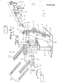
- 1 consists of a base plate 1, on which two columns 2 and 3 are attached.
- the column 3 While the column 3 is rigidly attached to the base plate 1, the column 2 is pivotally attached. For this purpose, it is connected to the base plate 1 via a hinge 2.1, for which purpose the hinge is attached in such a way that it can be tilted laterally.
- the column 3 is moved via a servomotor 2.2 fastened to the base plate 2.
- the clamping device 4 with its servomotor 5 is provided on the column 2.
- the servomotor is a hydraulically or pneumatically operated cylinder piston unit. This cylinder is rotatably attached to the column 2 by a fork 6.
- the free end of the piston rod is connected in an articulated manner to a connecting rod 7.
- This connecting rod 7 has two articulation points 8 and 9, which are arranged one above the other.
- an arm 10 is rotatably fastened, which has a sickle-shaped contour and is rotatably mounted in the clamping device 4.
- the clamping device 4 itself consists of the housing 11, in which the receiving part 12 is rotatably fastened.
- the receiving part 12 consists of a circular cylinder with a central bore 13.
- the central bore 13 serves to receive the electrode cap, not shown. It is serrated on its inner circumference in order to be able to hold the electrode against rotation.
- the arm 10 To attach the arm 10 to the receiving part 12, the latter is slotted on part of its outer circumference up to the receiving bore 13.
- the arm 10 engages in this slot. It is held by a pin 14, which is mounted in the receiving part 12.
- the arm 10 faces at its front with the receiving bore tion 13 cooperating end a circular segment-shaped section with a toothed circumferential surface so as to completely release the receiving bore 13 in the rest position.
- the receiving part 12 has at its lower, i.e. a region 15 facing the servomotor 5.
- control device 20 is attached to the column 3. It consists of two limit switches 21 and 22 arranged at a distance from the electrode shanks of the welding gun, which are equipped with actuating pins 23 and 24.
- a magazine 30 for new electrode caps is also provided on the column 3.
- the magazine 30 has a separating device 31 at its outlet. This consists of two jaws 32 and 33, which are kept at a distance via an energy accumulator 34. The distance between the jaws 32 and 33 is chosen such that an electrode cap can fall safely and easily into it.
- the electrode caps themselves are stacked in rails 35.
- the rails 35 are inclined at an angle to the horizontal, in such a way that the electrode caps located there can slide to the magazine outlet 36 under the influence of gravity.
- the magazine outlet 36 is in the rest position of the jaws 32 and 33 with their opening. All of the elements 31 - 36 of the magazine 30 described so far are present in duplicate.
- the magazine 30 is thus constructed as a double magazine in order to make the electrode cap holder as simple as possible for both welding gun shafts.
- the jaw pairs 32 and 33 are displaced perpendicularly to the magazine openings 36 up to a stop 38 by a single servomotor 37.
- the robot moves the welding gun in such a way that the other electrode shaft on the back of the holder bore 13 is. Now the column 2 is tilted back so that it envelops the electrode cap. In this case, the electrode cap that has already been removed in the receiving bore 13 is removed, tossed. The same removal process then takes place for the other electrode cap.
- the welding robot moves to the control device 20.
- the actuating pins 23 and 24 are at such a clear distance from one another that corresponds to the distance between the two welding gun shafts without an electrode cap. If both electrode caps are removed, the welding gun can be moved past the two actuating pins 23 and 24 without contact. If, however, one or both caps are not removed, one or both actuating pins are moved. This movement is detected by the corresponding limit switches 21 or 22 and leads to a backward movement of the welding robot towards the clamping device 4 in order to have the corresponding electrode cap removed again.
- the control device 20 is passed without actuating the two limit switches 21 and 22.
- the welding robot then moves on to the magazine 30. Due to the rest position of the two pairs of jaws 32 and 33, an electrode cap has slipped between each of the guide rails 35.
- the servomotor 37 is then actuated. As a result, the jaws 32 and, via the springs 34, the jaws 33 are displaced up to the stop 38. On the one hand, the magazine exits 36 are closed by this displacement movement, so that no electrode caps can slide down. On the other hand, when the jaws 33 hit the stop 38, the inserted electrode caps are clamped. In this position, the front electrode shaft is first immersed and then the rear one in the respective electrode cap. Then the servomotor 37 is relieved so that the jaw 31 can retreat due to the springs 34 and the electrode cap is released.
- the welding robot moves back to the control device 20 and passes it in the opposite direction. Due to the electrode caps picked up, the two actuating pins 23 and 24 are now deflected clockwise as they pass and actuate the associated limit switches 21 and 22. This signal means that both electrode caps are picked up. If a signal is missing, the control device of the welding robot knows that no electrode cap has been picked up on the side in question where the error signal originated. In this case, the welding robot is then moved back to the magazine so that the corresponding electrode shaft can accommodate a new electrode cap.
- the welding robot moves out of the area of the control device 20. Then the two welding gun boxes are pressed against each other. This ensures that the two pushed-on electrode caps are securely clamped on the electrode shafts. The robot is then ready for use again.
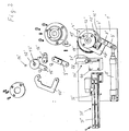
- FIG. 2 shows the electrode cap changing device according to the invention for welding robots with a picker. Since the picker consists of an electrode shaft with an attached electrode cap and is usually brought vertically into the welding position from above, the changing device shown in FIG. 2 is attached to a table, not shown in detail. It differs from the device shown in Fig. 1 only in that the clamping device 4 'is only accessible on one side and is not pivotable and that the magazine is formed only on one side and, accordingly, the control device consists of only one limit switch. The structure of the clamping device and its function is identical to the arrangement described in FIG. 1.
- the electrode is moved from the robot to the clamping device 4 ′ and there it lowers the electrode cap into the open receiving bore 13 ′. Then the clamping process described at the beginning takes place.
- the withdrawal movement which is simultaneously necessary while rotating the electrode cap is carried out by the robot itself by pulling the electrode out of the receiving bore 13 '.
- the control device 20 'and After the electrode shaft has been freed from the old electrode cap, has passed the control device 20 'and has received a new electrode cap from the magazine 30', it in turn travels to the control device 20 'and actuates the switching pin 23' there. Then he drives to the anvil 40 arranged between the electrode cap magazine 30 'and the control device 20'. Here, the electrode cap is pressed firmly onto the electrode shaft by repeated opening.
Abstract
Description
Verfahren zum selbsttätigen Auswechseln von Elektrodenkappen an Schweißelektrodenschäften sowie Vorrichtung zur Durchführung des VerfahrensProcess for the automatic replacement of electrode caps on welding electrode shafts and device for carrying out the process
Die Erfindung bezieht sich auf ein Verfahren der im Oberbegriff des ersten Anspruchs angegebenen Art sowie auf eine Vorrichtung zur Durchführung des Verfahrens.The invention relates to a method of the type specified in the preamble of the first claim and to an apparatus for performing the method.
Aus der DE-OS 33 23 038 ist das gattungsgemäße Verfahren bekannt. Bei diesem Verfahren wird der Elektrodenschaft über eine separate Spanneinrichtung mit Stellmotor geklemmt und dann die Elektrodenkappe über eine Klemmeinrichtung mit ebenfalls separatem Stellmotor festgeklemmt und in Drehung versetzt, wobei über eine Kulissenführung gleichzeitig die Abziehbewegung der Elektrodenkappe durchgeführt wird. In unmittelbarer Nachbarschaft zu dieser Wechselstation ist ein Elektrodenkappenmagazin mit zugeordnetem Amboß vorgesehen. Nach erfolgtem Elektrodenkappenabzug wird der Elektrodenschaft zu diesem Magazin verfahren, nimmt dort eine Elektrodenkappe auf und schlägt sie auf dem Amboß fest.The generic method is known from DE-OS 33 23 038. In this method, the electrode shaft is clamped via a separate clamping device with a servomotor and then the electrode cap is clamped and rotated via a clamping device with a likewise separate servomotor, the pulling movement of the electrode cap being carried out simultaneously via a link guide. In the immediate vicinity of this changing station, an electrode cap magazine with an anvil is provided. After the electrode cap has been removed, the electrode shaft is moved to this magazine, picks up an electrode cap there and strikes it on the anvil.
Diese Vorrichtung hat sich prinzipiell hervorragend bewährt. Nachteilig hierbei ist jedoch nur die Verwendung bei Portalrobotern, der erhöhte Platzbedarf sowie die fehlende Kontrolle, ob die Elektrodenkappe ordnungsgemäß abgezogen wurde und ob tatsächlich eine neue Kappe aufgenommen wurde.In principle, this device has proven itself extremely well. The disadvantage here, however, is only the use with portal robots, the increased space requirement and the lack of control as to whether the electrode cap has been removed properly and whether a new cap has actually been picked up.
Aufgabe der vorliegenden Erfindung ist, das gattungsgemäße Verfahren zu vereinfachen. Diese Aufgabe wird erfindungsgemäß durch die kennzeichnenden Merkmale des ersten Anspruchs gelöst. Die Lösung basiert auf der Erkenntnis, daß es zum Abziehen der Elektrodenkappe nicht notwendig ist, den Elektrodenschaft von einer besonderen Halteeinrichtung festzuklemmen. Üblicherweise ist der Elektrodenschaft an einem Schweißroboter befestigt. Dieser kann die notwendige Gegenkraft beim Drehen und auch die Haltekraft bei der Abzugsbewegung aufbringen.The object of the present invention is to simplify the generic method. This object is achieved according to the invention by the characterizing features of the first claim. The solution is based on the knowledge that it is not necessary to remove the electrode cap by clamping the electrode shaft with a special holding device. The electrode shaft is usually attached to a welding robot. This can apply the necessary counterforce when turning and also the holding force during the trigger movement.
Die Weiterbildung des Verfahrens nach Anspruch 2 hat den Vorteil, daß bei selbsttätig von einem Schweißroboter durchgeführten Elektrodenkappenwechsel sichergestellt ist, daß nicht versucht werden soll, eine neue Elektrodenkappe aufzunehmen, wenn die alte nicht abgezogen wurde.The development of the method according to
Da es theoretisch auch vorkommen kann, daß die neu aufgenommene Elektrodenkappe nicht an dem Elektrodenschaft haften bleibt und um in diesem Fall sicherzustellen, daß nicht ohne aufgesetzte Elektrodenkappe versucht wird zu schweißen, wird die Weiterbildung nach Anspruch 3 vorgeschlagen.Since it can theoretically also happen that the newly received electrode cap does not stick to the electrode shaft and to ensure in this case that attempts are not made to weld without the electrode cap being attached, the further development according to
Die Merkmale des Anspruchs 4 beschreiben eine zum Durchführen des erfindungsgemäßen Verfahrens besonders geeignete Vorrichtung. Durch diese Anordnung ist es möglich, mit einem einzigen Stellmotor den gesamten Elektrodenwechsel durchzuführen, da die Halte- und Abzugskräfte von dem Schweißroboter selbst bzw. von der Bedienungsperson aufgebracht werden können. Dadurch vereinfacht sich der konstruktive Aufwand gegenüber der bisher bekannten Anordnung erheblich, womit auch ihre Störanfälligkeit sinkt. Durch die Verwendung nur eines einzigen Stellmotors ist es zudem möglich, daß die Vorrichtung direkt neben den Schweißrobotern aufgestellt werden kann, da der Platzbedarf hierfür äußerst gering ist. Die bisher bekannte Vorrichtung war hierzu weniger geeignet, da aufgrund des benötigten Platzbedarfes und des tatsächlich vorhandenen diese nur vereinzelt angewendet werden konnte.The features of
Sollten die Elektrodenkappen an einer Schweißzange gewechselt werden, so ist es schaltungstechnisch einfacher, wenn die Abzugsbewegung der Kappen von der Klemmeinrichtung ausgeführt wird als sie von dem Roboter ausführen zu lassen. Hierfür beschreibt die Weiterbildung nach Anspruch 5 eine geeignete Ausbildung.If the electrode caps are changed on a welding gun, it is simpler in terms of circuitry if the pulling-off movement of the caps is carried out by the clamping device than to have them carried out by the robot. For this purpose, the training according to
Durch die Weiterbildung nach Anspruch 6 wird eine sehr kompakte Bauweise des Aufnahmeteils erreicht. Ein weiterer Vorteil ist darin zu sehen, daß der Arm die Elektrodenkappe gegen die gegenüberliegende Innenwand des Aufnahmeteils drücken kann, so daß ein Verkanten der Elektrodenkappe und damit eine Behinderung beim Drehen und Abziehen nicht auftreten kann.Through the development according to
Umsein Durchrutschen des Aufnahmeteils auf der Elektrodenkappe zu vermeiden, ist die Ausbildung nach Anspruch 7 oder 8 oder gemeinsame Verwendung der beiden in Anspruch 7 und 8 beschriebenen Merkmale sinnvoll.In order to avoid slippage s of the receiving part on the electrode cap, the embodiment according to
Die Ansprüche 9 und 10 beschreiben eine geeignete Kontrolleinrichtung. Die Kontrolleinrichtung ist nach den Merkmalen des Anspruchs 9 sinnvollerweise in räumlicher Nachbarschaft zum Aufnahmeteil angeordnet, damit sofort nach Abziehen der Elektrodenkappe der Kontrollvorgang durchgeführt werden kann. Als Kontrolleinrichtung hat sich ein Endlagenschalter bewährt. Dieser wird von dem Elektrodenschaft derart angefahren, daß bei abgezogener Elektrodenkappe keine Betätigung des Schalters erfolgt, wohingegen bei nicht abgezogener Elektrode ein Fehlersignal erfolgt. Auch kann diese Kontrolleinrichtung dazu verwendet werden festzustellen, ob eine neue Elektrodenkappe sicher aufgenommen wurde. Hierzu ist es nur erforderlich, den Verfahrweg während des Kontrollvorganges umzudrehen, so daß der Endlagenschalter in der entgegengesetzten Richtung betätigt werden muß um festzustellen, daß eine Elektrodenkappe sicher aufgenommen wurde.
Durch die Weiterbildung nach Anspruch 11 wird der Vorteil erreicht, daß der Elektrodenschaft geradlinig zum Magazin weiterbewegt werden kann, um dort eine neue Elektrodenkappe aufzunehmen. Dies stellt bei Verwendung von Schweißrobotern einen programmiertechnisch einfachen Vorgang dar.Through the development according to
Um bei Verwendung von Schweißzangen eine sichere Elektrodenkappenaufnahme zu gewährleisten, ist die Weiterbildung nach Anspruch 11 vorteilhaft.In order to ensure a secure electrode cap holder when using welding guns, the development according to
Eine geeignete Vereinzelungseinrichtung beschreibt Anspruch 12. Hiermit wird der Vorteil erreicht, daß während der Kappenaufnahme diese sicher gehalten werden kann, so daß eine eindeutige Lage der Elektrodenkappe vorhanden ist.A suitable separating device is described in
Eine besonders einfache Ausführung des Magazins mit Verriegelungseinrichtung beschreibt der Anspruch 13. Dadurch entfalten zusätzliche Steuereinrichtungen, um die Elektrodenkappen aus dem Magazin in die Vereinzelungseinrichtung zu überführen.
Im folgenden wird die Erfindung anhand eines ausgewählten Beispiels näher dargestellt.The invention is illustrated in more detail below with the aid of a selected example.
Es stellen dar:
- Fig. 1 eine erfindungsgemäß aufgebaute Elektrodenkappenwechselstation für Schweißzangen;
- Fig. 2 eine erfindungsgemäß aufgebaute Wechselstation für Picker.
- 1 shows an electrode cap changing station for welding guns constructed in accordance with the invention;
- 2 an exchange station for pickers constructed according to the invention.
Die erfindungsgemäß aufgebaute Wechselstation nach Fig. 1 besteht aus einer Grundplatte 1, auf der zwei Säulen 2 und 3 befestigt sind.1 consists of a
Während die Säule 3 starr an der Grundplatte 1 befestigt ist, ist die Säule 2 verschwenkbar befestigt. Hierzu ist sie über ein Scharnier 2.1 mit der Grundplatte 1 verbunden, wofür das Scharnier derart angebracht ist, daß sie seitlich kippbar ist. Bewegt wird die Säule 3 über einen auf der Grundplatte 2 befestigten Stellmotor 2.2.While the
An der Säule 2 ist die Klemmeinrichtung 4 mit ihrem Stellmotor 5 vorgesehen. Der Stellmotor ist in diesem Beispiel eine hydraulisch oder pneumatisch betätigte Zylinderkolbeneinheit. Diese ist mit ihrem Zylinder drehbar über ein Gabelstück 6 an der Säule 2 befestigt.The
Die Kolbenstange ist an ihrem freien Ende gelenkig verbunden mit einer Verbindungsstange 7. Diese Verbindungsstange 7 weist zwei Anlenkpunkte 8 und 9 auf, welche übereinander angeordnet sind. An dem Anlenkpunkt 8 ist ein Arm 10 drehbar befestigt, welcher eine sichelförmige Kontur aufweist und in der Klemmeinrichtung 4 drehbar gelagert ist. Die Klemmeinrichtung 4 selbst besteht aus dem Gehäuse 11, in welchem das Aufnahmeteil 12 drehbar befestigt ist. Das Aufnahmeteil 12 besteht aus einem Kreiszylinder mit Mittenbohrung 13. Die Mittenbohrung 13 dient zur Aufnahme der nicht dargestellten Elektrodenkappe. Sie ist auf ihrem Innenumfang gezahnt, um die Elektrode verdrehsicher aufnehmen zu können.The free end of the piston rod is connected in an articulated manner to a connecting rod 7. This connecting rod 7 has two
Zur Befestigung des Armes 10 an dem Aufnahmeteil 12 ist dieses auf einem Teil seines Außenumfangs bis zur Aufnahmebohrung 13 geschlitzt. In diesen Schlitz greift der Arm 10 ein. Gehalten wird er durch einen Stift 14, welcher in dem Aufnahmeteil 12 gelagert ist. Der Arm 10 weist an seinem vorderen mit der Aufnahmebohrung 13 zusammenwirkenden Ende einen kreissegmentförmigen Abschnitt mit gezahnter Umfangsfläche auf, um so in Ruheposition die Aufnahmebohrung 13 vollständig freizugeben.To attach the
Das Aufnahmeteil 12 weist an seinem unteren, d.h. dem Stellmotor 5 zugewandten Bereich einen Ansatz 15 auf. An dem Ansatz 15 greift ein Hebel 16 an, der mit dem oberen Anlenkpunkt 9 der Verbindungsstange 7 verbunden ist.The
In Ruhestellung wird der Hebel 16 von einem Federpaar 17 zurückgezogen. Dadurch ist sichergestellt, daß in dieser Stellung die Aufnahmebohrung 13 frei zugänglich ist, da über die Verbindungsstange 7 der Arm 10 aus dem Bereich der Aufnahmebohrung 13 herausgeschwenkt ist.In the rest position, the
Neben dieser Klemmeinrichtung 4 ist die Kontrolleinrichtung 20 an der Säule 3 befestigt. Sie besteht aus zwei im Abstand der Elektrodenschäfte der Schweißzange angeordneten Endlagenschalter 21 und 22, die mit Betätigungsstiften 23 und 24 ausgerüstet sind.In addition to this
An der Säule 3 ist ebenfalls ein Magazin 30 für neue Elektrodenkappen vorgesehen. Das Magazin 30 weist an seinem Ausgang eine Vereinzelungseinrichtung 31 auf. Diese besteht aus zwei Backen 32 und 33, die über einen Kraftspeicher 34 auf Abstand gehalten werden. Der Abstand der Backen 32 und 33 ist derart gewählt, daß eine Elektrodenkappe sicher und leicht hineinfallen kann. Die Elektrodenkappen selbst sind in Schienen 35 gestapelt. Die Schienen 35 sind unter einem Winkel zur Horizontalen geneigt, derart, daß die dort befindlichen Elektrodenkappen unter Einwirkung der Schwerkraft zum Magazinausgang 36 nachrutschen können. Der Magazinausgang 36 fluchtet in Ruhestellung der Backen 32 und 33 mit deren Öffnung. Alle bisher beschriebenen Elemente 31 - 36 des Magazins 30 sind zweifach vorhanden. Das Magazin 30 ist also als Doppelmagazin aufgebaut, um für beide Schweißzangenschäfte die Elektrodenkappenäufnahme so einfach wie möglich zu gestalten.A
Die Backenpaare 32 und 33 werden von einem einzigen Stellmotor 37 senkrecht zu den Magazinöffnungen 36 bis zu einem Anschlag 38 verschoben.The jaw pairs 32 and 33 are displaced perpendicularly to the
Die erfindungsgemäße Vorrichtung arbeitet wie folgt:
- Sollen von einer Schweißzange die beiden Elektrodenkappen gewechselt werden, so erhält der die Schweißzange tragende Roboter einen geeigneten Steuerbefehl. Aufgrund dieses Steuerbefehls fährt der Schweißroboter mit der Schweißzange zur Klemmeinrichtung 4. Die Schweißzange mit der abzuziehenden Elektrodenkappe wird derart vor der Aufnahmebohrung 13 positioniert, daß durch eine Schwenkbewegung der Säule 2 durch den Stellmotor 2.2
die Aufnahmebohrung 13 die abzuziehende Elektrodenkappe umschließt. Dadurch wird die Elektrodenkappe indie Aufnahmebohrung 13 eingetaucht. Sodann wird der Stellmotor 5 eingeschaltet. Die herausfahrende Kolbenstange dreht die Verbindungsstange 7 um den Anlenkpunkt 9. Dies ist deshalb möglich, da dieser über dieFeder 17 gehalten wird. Durch diese Drehbewegung wird derArm 10um seine Achse 14 gedreht und klemmt dadurch die Elektrodenkappe inder Aufnahmebohrung 13 fest.
- If the two electrode caps are to be replaced by a welding gun, the robot carrying the welding gun receives a suitable control command. On the basis of this control command, the welding robot moves with the welding gun to the
clamping device 4. The welding gun with the electrode cap to be removed is positioned in front of the receiving bore 13 in such a way that the receiving bore 13 encloses the electrode cap to be removed by a pivoting movement of thecolumn 2 by the servomotor 2.2. As a result, the electrode cap is immersed in the receiving bore 13. Theservomotor 5 is then switched on. The extending piston rod rotates the connecting rod 7 around the articulation point 9. This is possible because it is held by thespring 17. As a result of this rotary movement, thearm 10 is rotated about itsaxis 14 and thereby clamps the electrode cap in the receiving bore 13.
Die weitere Ausfahrbewegung der Kolbenstange des Stellmotors 5 erreicht, daß die Drehkraft auf die Verbindungsstange 7 die Rückhaltekraft der Federn 17 überwindet, so daß sich nun auch zusätzlich zum Arm 10 das Aufnahmeteil 12 im Gehäuse 11 dreht. Dadurch wird die festgeklemmte Elektrodenkappe auf dem Elektrodenschaft gedreht. Gleichzeitig bei dieser Drehbewegung verschwenkt der Stellmotor 2.2 die Säule 2 in Richtung von dem Elektrodenschaft weg. Durch die überlagerte Dreh- und Zugbewegung wird die Elektrodenkappe vom Elektrodenschaft abgezogen.The further extension movement of the piston rod of the
Sobald die Elektrodenkappe vollständig von dem Elektrodenschaft gelöst ist, verfährt der Roboter die Schweißzange derart, daß nunmehr der andere Elektrodenschaft an der Rückseite der Aufnahmebohrung 13 steht. Nunmehr wird die Säule 2 nach hinten gekippt, so daß sie die Elektrodenkappe umhüllt. Hierbei wird die noch in der Aufnahmebohrung 13 vorhandene bereits abgezogene Elektrodenkappe ausges, tossen. Bei der anderen Elektrodenkappe erfolgt dann der gleiche Abziehvorgang.As soon as the electrode cap is completely detached from the electrode shaft, the robot moves the welding gun in such a way that the other electrode shaft on the back of the holder bore 13 is. Now the
Sobald beide Kappen abgezogen sind, fährt der Schweißroboter zur Kontrolleinrichtung 20. Die Betätigungsstifte 23 und 24 haben einen derart lichten Abstand voneinander, der dem Abstand der beiden Schweißzangenschäfte ohne Elektrodenkappe entspricht. Sind also beide Elektrodenkappen abgezogen, so kann die Schweißzange berührungsfrei an den beiden Betätigungsstiften 23 und 24 vorbeibewegt werden. Ist hingegen eine oder sind beide Kappen nicht abgezogen, so wird ein oder werden beide Betätigungsstifte bewegt. Diese Bewegung wird von den entsprechenden Endschaltern 21 oder 22 erfaßt und führt zu einer Rückwärtsbewegung des Schweißroboters hin zur Klemmeinrichtung 4, um die entsprechende Elektrodenkappe erneut abziehen zu lassen.As soon as both caps have been removed, the welding robot moves to the
Sind beide Elektrodenkappen abgezogen, so wird die Kontrolleinrichtung 20 ohne Betätigung der beiden Endlagenschalter 21 und 22 passiert. Sodann fährt der Schweißroboter weiter zum Magazin 30. Aufgrund der Ruhestellung der beiden Backenpaare 32 und 33 sind zwischen ihnen aus den Führungsschienen 35 je eine Elektrodenkappe nachgerutscht. Sodann wird der Stellmotor 37 betätigt. Dadurch werden die Backen 32 und über die Federn 34 die Backen 33 verschoben bis zu dem Anschlag 38. Durch diese Verschiebebewegung werden zum einen die Magazinausgänge 36 verschlossen, so daß keine Elektrodenkappen nachrutschen können. Zum anderen werden durch das Auftreffen der Backen 33 auf den Anschlag 38 die eingelagerten Elektrodenkappen geklemmt. In dieser Position taucht nun zuerst der vordere Elektrodenschaft und dann der hintere in die jeweilige Elektrodenkappe ein. Sodann wird der Stellmotor 37 entlastet so daß die Backe 31 aufgrund der Federn 34 zurückweichen kann und die Elektrodenkappe freigibt.If both electrode caps are removed, the
Nach der Aufnahme der beiden Elektrodenkappen fährt der Schweißroboter wieder zurück zur Kontrolleinrichtung 20 und passiert diese in der umgekehrten Richtung. Aufgrund der aufgenommenen Elektrodenkappen werden nun die beiden Betätigungsstifte 23 und 24 beim Passieren im Uhrzeigersinn ausgelenkt und betätigen die zugehörigen Endschalter 21 und 22. Dieses Signal bedeutet, daß beide Elektrodenkappen aufgenommen sind. Fehlt ein Signal, so weiß die Steuereinrichtung des Schweißroboters, daß auf der betreffenden Seite, wo das Fehlersignal entstanden ist, keine Elektrodenkappe aufgenommen wurde. In- diesem Fall wird dann der Schweißroboter wieder zurück zum Magazin gefahren, so daß der entsprechende Elektrodenschaft eine neue Elektrodenkappe aufnehmen kann.After the two electrode caps have been picked up, the welding robot moves back to the
Sobald die Kontrolleinrichtung 20 das Vorhandensein von zwei Elektrodenkappen gemeldet hat, fährt der Schweißroboter aus dem Bereich der Kontrolleinrichtung 20 hinaus. Sodann werden die beiden Schweißzangenschatle geneinander gedrückt. Dadurch wird erreicht, daß die beiden aufgeschobenen Elektrodenkappen sicher auf den Elektrodenschäften geklemmt werden. Anschließend ist der Roboter wieder einsatzbereit.As soon as the
In Fig. 2 ist die erfindungsgemäße Elektrodenkappenwechseleinrichtung für Schweißroboter mit einem Picker dargestellt. Da der Picker aus einem Elektrodenschaft mit angesetzter Elektrodenkappe besteht und überlicherweise senkrecht von oben in Schweißposition gebracht wird, ist die in Fig. 2 dargestellte Wechseleinrichtung auf einem nicht näher dargestellten Tisch befestigt. Sie unterscheidet sich ab von der in Fig. 1 dargestellten Einrichtung nur dadurch, daß die Klemmeinrichtung 4' nur einseitig zugänglich ist und nicht verschwenkbar angeordnet ist und daß das Magazin nur einseitig ausgebildet ist und dementsprechend auch die Kontrolleinrichtung nur aus einem Endlagenschalter besteht. Der Aufbau der Klemmeinrichtung und deren Funktion ist identisch mit der in Fig. 1 beschriebenen Anordnung.2 shows the electrode cap changing device according to the invention for welding robots with a picker. Since the picker consists of an electrode shaft with an attached electrode cap and is usually brought vertically into the welding position from above, the changing device shown in FIG. 2 is attached to a table, not shown in detail. It differs from the device shown in Fig. 1 only in that the clamping device 4 'is only accessible on one side and is not pivotable and that the magazine is formed only on one side and, accordingly, the control device consists of only one limit switch. The structure of the clamping device and its function is identical to the arrangement described in FIG. 1.
Das Elektrodenkappenmagazin 30' weicht insofern von dem in Fig. 1 dargestellten ab, als hier keine Vereinzelungseinrichtung vorgesehen ist. Die einzelnen Elektrodenkappen in der horizontal angeordneten Führung 35' sind federbelastet und werden über einen Schieber 32' zum Magazinausgang 36'geführt.The electrode cap magazine 30 'differs from that shown in FIG. 1 in that no separating device is provided here. The individual electrode caps in the horizontally arranged guide 35 'are spring-loaded and are guided to the magazine outlet 36' via a slide 32 '.
Zum Wechseln der Elektrodenkappe wird die Elektrode von dem Roboter zur Klemmeinrichtung 4' verfahren und senkt dort die Elektrodenkappe in die geöffnete Aufnahmebohrung 13'. Sodann läuft der eingangs beschriebene Klemmvorgang ab. Die unter Drehen der Elektrodenkappe gleichzeitig notwendige Abzugsbewegung wird durch den Roboter selbst ausgeführt, in dem er die Elektrode aus der Aufnahmebohrung 13' herauszieht.To change the electrode cap, the electrode is moved from the robot to the
Nachdem der Elektrodenschaft von der alten Elektrodenkappe befreit wurde, die Kontrolleinrichtung 20' passiert hat und eine neue Elektrodenkappe aus dem Magazin 30' aufgenommen hat, fährt er wiederum zur Kontrolleinrichtung 20' und betätigt dort den Schaltstift 23'. Sodann fährt er zu dem zwischen dem Elektrodenkappenmagazin 30' und der Kontrolleinrichtung 20' angeordneten Amboß 40. Hier wird durch mehrmaliges Aufschlagen die Elektrodenkappe fest auf den Elektrodenschaft gepreßt.After the electrode shaft has been freed from the old electrode cap, has passed the control device 20 'and has received a new electrode cap from the magazine 30', it in turn travels to the control device 20 'and actuates the switching pin 23' there. Then he drives to the
Claims (15)
dadurch gekennzeichnet, daß der Schweißelektrodenschaft zum Abziehen der Elektrodenkappe während ihres Drehens vom Schweißroboter verdrehsicher gehalten, und daß der Schweißelektrodenschaft oder die Elektrodenkappe gleichzeitig zurückgezogen wird.1. A method for the automatic replacement of electrode caps on welding electrode shafts, in particular for pickers or welding tongs of welding robots, the electrode cap being clamped and rotated for changing, and after the welding electrode shaft has been pulled off, it is shifted to an electrode cap magazine, immersed therein in an electrode cap and then hammered on,
characterized in that the welding electrode shaft for removing the electrode cap is held against rotation by the welding robot during its rotation, and in that the welding electrode shaft or the electrode cap is withdrawn at the same time.
dadurch gekennzeichnet, daß an dem Aufnahmeteil (12) außermittig ein Hebel (16) drehbar befestigt, der mit seinem freien Ende drehbar an einer verschwenkbar mit dem Stellmotor (5) verbundenen Verbindungsstange (7) gelagert ist, daß der Anlenkpunkt zwischen dem Aufnahmeteil (12)und dem Hebel (16) federbelastet (Federpaar 17) ist, daß das Spannteil aus einem sichelförmigen Arm (10) , der einerseits derart außermittig an dem Aufnahmeteil (12) gelagert ist, daß er bei Verschwenken einen Teil der Aufnahmebohrung (13) verschließt, und andererseits mit Abstand vom Anlenkpunkt (9) des Hebels (16) an der Verbindungsstange gelagert ist.4. Device for carrying out the method, consisting of a guided welding electrode shaft with a detachably fastened Electrode cap and a changing station, consisting essentially of a rotatably mounted clamping device which can be actuated by a servomotor for clamping and rotating the electrode cap about its longitudinal axis, for which purpose the clamping device consists of a receptacle part which is rotatably mounted about its longitudinal axis and is connected to the servomotor and has a central locating bore and one there is also a rotatably mounted clamping part,
characterized in that a lever (16) is rotatably attached to the center of the receiving part (12), the free end of which is rotatably mounted on a connecting rod (7) which is pivotably connected to the servomotor (5), that the articulation point between the receiving part (12 ) and the lever (16) spring-loaded (pair of springs 17) is that the clamping part from a crescent-shaped arm (10), which is mounted on the one hand so eccentrically on the receiving part (12) that it closes part of the receiving bore (13) when pivoted , and on the other hand at a distance from the articulation point (9) of the lever (16) on the connecting rod.
Applications Claiming Priority (2)
| Application Number | Priority Date | Filing Date | Title |
|---|---|---|---|
| DE19853515597 DE3515597A1 (en) | 1985-04-30 | 1985-04-30 | METHOD FOR AUTOMATICALLY REPLACING ELECTRODE CAPS ON WELDING ELECTRODE SHAFTS AND DEVICE FOR IMPLEMENTING THE METHOD |
| DE3515597 | 1985-04-30 |
Publications (3)
| Publication Number | Publication Date |
|---|---|
| EP0200162A2 true EP0200162A2 (en) | 1986-11-05 |
| EP0200162A3 EP0200162A3 (en) | 1987-10-28 |
| EP0200162B1 EP0200162B1 (en) | 1989-07-05 |
Family
ID=6269509
Family Applications (1)
| Application Number | Title | Priority Date | Filing Date |
|---|---|---|---|
| EP19860105665 Expired EP0200162B1 (en) | 1985-04-30 | 1986-04-24 | Process for automatically exchanging electrode caps at weld electrode shafts, and device for carrying out the process |
Country Status (2)
| Country | Link |
|---|---|
| EP (1) | EP0200162B1 (en) |
| DE (1) | DE3515597A1 (en) |
Cited By (15)
| Publication number | Priority date | Publication date | Assignee | Title |
|---|---|---|---|---|
| EP0267109A1 (en) * | 1986-11-06 | 1988-05-11 | Automobiles Peugeot | Automatic welding robot electrode replacing device |
| GB2216449A (en) * | 1988-02-04 | 1989-10-11 | Honda Motor Co Ltd | Electrode tip replacement for a welding gun |
| DE3822655C1 (en) * | 1988-07-05 | 1990-02-01 | Werner 8904 Friedberg De Semmlinger | Method of automatically removing electrode caps from welding electrode shanks, and device for carrying out the method |
| FR2760391A1 (en) * | 1997-03-06 | 1998-09-11 | Roger Louzier | DEVICE FOR THE MAINTENANCE OF PROGRAMMABLE AUTOMATONS |
| FR2779077A1 (en) * | 1998-05-26 | 1999-12-03 | Peugeot | Spot arc welding apparatus electrode tip pullout unit |
| DE29914968U1 (en) * | 1999-08-26 | 2001-01-04 | Kuka Schweissanlagen Gmbh | Change device for electrode caps |
| EP1110657A1 (en) * | 1999-12-21 | 2001-06-27 | Kyokutoh Company | Device for removing electrode tip |
| FR2874523A1 (en) * | 2004-08-30 | 2006-03-03 | Roger Louzier | Electrodes loading and storing device for spot welding robot has cartridge with electrodes that are driven to loading station having panels to constitute cell used for storing and loading stand by electrode for one arm of pliers |
| FR2895926A1 (en) * | 2006-01-11 | 2007-07-13 | Roger Louzier | Charger for changing the electrodes of a welding robot clamp with facility for electrodes of different sizes and stabilization of electrode positioning, notably for a motor vehicle fabrication line |
| WO2009007773A1 (en) * | 2007-07-11 | 2009-01-15 | Roger Louzier | Multi-gauge precision electrode loader with improved reliability |
| CN105710545A (en) * | 2014-12-03 | 2016-06-29 | 长沙华恒机器人系统有限公司 | Pole needle welding device |
| US9757814B2 (en) | 2005-07-28 | 2017-09-12 | Copperhead Industrial Inc. | Spot welding cap changer |
| CN108608103A (en) * | 2018-04-28 | 2018-10-02 | 合肥巨智能装备有限公司 | A kind of stowage and loading attachment including the electrode cap including offest electrode cap |
| CN114083193A (en) * | 2021-10-25 | 2022-02-25 | 郑州日产汽车有限公司 | Co-polar positioning puppet welding system for vehicle door guide groove |
| CN115255590A (en) * | 2022-08-10 | 2022-11-01 | 郑州日产汽车有限公司 | Automatic cap feeding equipment for mounting electrode caps of welding robot |
Families Citing this family (14)
| Publication number | Priority date | Publication date | Assignee | Title |
|---|---|---|---|---|
| US5102280A (en) | 1989-03-07 | 1992-04-07 | Ade Corporation | Robot prealigner |
| US5073692A (en) * | 1990-11-13 | 1991-12-17 | Jackson Donald T | Automatic welding electrode cap changer |
| CA2121988A1 (en) * | 1994-04-22 | 1995-10-23 | Laurent Voilmy | Apparatus for automatically replacing welding electrodes |
| DE19724371C1 (en) * | 1997-06-10 | 1998-10-01 | Werner Kaeseler | System for programme controlled automatic changing of robot spot welder electrodes |
| DE19741419C2 (en) * | 1997-09-19 | 2001-05-23 | Audi Ag | Device for replacing an electrode end piece attached to an electrode end of a robot spot welding gun |
| DE19825770C2 (en) * | 1998-06-09 | 2000-05-04 | Bayerische Motoren Werke Ag | Device for putting on electrode caps |
| DE29905872U1 (en) * | 1999-03-31 | 1999-06-17 | Nimak Automatisierte Schweiste | Device for the automated changing of electrode caps on welding electrode shafts |
| DE19960877A1 (en) * | 1999-12-17 | 2001-06-21 | Abb Patent Gmbh | Method for changing an electrode cap of a welding gun |
| US6667454B2 (en) | 2002-04-29 | 2003-12-23 | Robtex Inc. | Apparatus and method for separating and replacing a cap from a shank of a tip of a welding electrode |
| DE102010061546B4 (en) | 2010-12-23 | 2012-08-02 | Bayerische Motoren Werke Aktiengesellschaft | Device and method for releasing electrode caps |
| DE102012201671A1 (en) | 2012-02-06 | 2013-08-08 | Bayerische Motoren Werke Aktiengesellschaft | Cap mounting system for electrode cap of robot-controlled welding tong, has cap supply having refilling aperture that is extended outside of working range of welding tongs toward cap retainer and is closed in cross-sectional area |
| DE102016201700A1 (en) | 2016-02-04 | 2017-08-10 | GFi Gesellschaft für technische Ingenieurleistungen mbH | Tool for removing an electrode cap from an electrode shaft |
| CN106563876A (en) * | 2016-10-20 | 2017-04-19 | 南京君哲工业自动化有限公司 | Roll spring electrode cap storage unit |
| CN113042872B (en) * | 2021-04-29 | 2024-04-19 | 扬帆研华(天津)科技发展有限公司 | Double-jaw automatic cap replacing machine with self-adaptive adjustment of clamping force and torque rotation plane |
Citations (1)
| Publication number | Priority date | Publication date | Assignee | Title |
|---|---|---|---|---|
| DE3323038A1 (en) * | 1983-06-25 | 1985-01-10 | Bayerische Motoren Werke AG, 8000 München | Apparatus for automatically exchanging the end piece of a welding electrode |
Family Cites Families (1)
| Publication number | Priority date | Publication date | Assignee | Title |
|---|---|---|---|---|
| FR2479065A1 (en) * | 1980-03-28 | 1981-10-02 | Dietrich & Cie De | TOOL FOR DISASSEMBLY OF ELECTRODES FROM SPOT WELDING MACHINES |
-
1985
- 1985-04-30 DE DE19853515597 patent/DE3515597A1/en active Granted
-
1986
- 1986-04-24 EP EP19860105665 patent/EP0200162B1/en not_active Expired
Patent Citations (1)
| Publication number | Priority date | Publication date | Assignee | Title |
|---|---|---|---|---|
| DE3323038A1 (en) * | 1983-06-25 | 1985-01-10 | Bayerische Motoren Werke AG, 8000 München | Apparatus for automatically exchanging the end piece of a welding electrode |
Cited By (22)
| Publication number | Priority date | Publication date | Assignee | Title |
|---|---|---|---|---|
| EP0267109A1 (en) * | 1986-11-06 | 1988-05-11 | Automobiles Peugeot | Automatic welding robot electrode replacing device |
| FR2606308A1 (en) * | 1986-11-06 | 1988-05-13 | Peugeot | AUTOMATIC DEVICE FOR REPLACING ELECTRODES OF A WELDING ROBOT |
| GB2216449A (en) * | 1988-02-04 | 1989-10-11 | Honda Motor Co Ltd | Electrode tip replacement for a welding gun |
| US4935595A (en) * | 1988-02-04 | 1990-06-19 | Honda Giken Kogyo Kabushiki Kaisha | Electrode tip replacement apparatus for welding gun |
| GB2216449B (en) * | 1988-02-04 | 1992-06-17 | Honda Motor Co Ltd | Electrode tip replacement apparatus for a welding gun |
| DE3822655C1 (en) * | 1988-07-05 | 1990-02-01 | Werner 8904 Friedberg De Semmlinger | Method of automatically removing electrode caps from welding electrode shanks, and device for carrying out the method |
| FR2760391A1 (en) * | 1997-03-06 | 1998-09-11 | Roger Louzier | DEVICE FOR THE MAINTENANCE OF PROGRAMMABLE AUTOMATONS |
| WO1998039134A1 (en) * | 1997-03-06 | 1998-09-11 | Roger Louzier | Device for the maintenance of programmable automatons |
| FR2779077A1 (en) * | 1998-05-26 | 1999-12-03 | Peugeot | Spot arc welding apparatus electrode tip pullout unit |
| DE29914968U1 (en) * | 1999-08-26 | 2001-01-04 | Kuka Schweissanlagen Gmbh | Change device for electrode caps |
| EP1110657A1 (en) * | 1999-12-21 | 2001-06-27 | Kyokutoh Company | Device for removing electrode tip |
| FR2874523A1 (en) * | 2004-08-30 | 2006-03-03 | Roger Louzier | Electrodes loading and storing device for spot welding robot has cartridge with electrodes that are driven to loading station having panels to constitute cell used for storing and loading stand by electrode for one arm of pliers |
| US9757814B2 (en) | 2005-07-28 | 2017-09-12 | Copperhead Industrial Inc. | Spot welding cap changer |
| FR2895926A1 (en) * | 2006-01-11 | 2007-07-13 | Roger Louzier | Charger for changing the electrodes of a welding robot clamp with facility for electrodes of different sizes and stabilization of electrode positioning, notably for a motor vehicle fabrication line |
| WO2009007773A1 (en) * | 2007-07-11 | 2009-01-15 | Roger Louzier | Multi-gauge precision electrode loader with improved reliability |
| CN105710545A (en) * | 2014-12-03 | 2016-06-29 | 长沙华恒机器人系统有限公司 | Pole needle welding device |
| CN108608103A (en) * | 2018-04-28 | 2018-10-02 | 合肥巨智能装备有限公司 | A kind of stowage and loading attachment including the electrode cap including offest electrode cap |
| CN108608103B (en) * | 2018-04-28 | 2020-10-09 | 合肥巨一智能装备有限公司 | Loading method and loading device for electrode cap including eccentric electrode cap |
| CN114083193A (en) * | 2021-10-25 | 2022-02-25 | 郑州日产汽车有限公司 | Co-polar positioning puppet welding system for vehicle door guide groove |
| CN114083193B (en) * | 2021-10-25 | 2023-05-12 | 郑州日产汽车有限公司 | Co-electrode positioning puppet welding system for vehicle door guide groove |
| CN115255590A (en) * | 2022-08-10 | 2022-11-01 | 郑州日产汽车有限公司 | Automatic cap feeding equipment for mounting electrode caps of welding robot |
| CN115255590B (en) * | 2022-08-10 | 2023-08-15 | 郑州日产汽车有限公司 | Automatic cap loading equipment for welding robot electrode cap installation |
Also Published As
| Publication number | Publication date |
|---|---|
| EP0200162B1 (en) | 1989-07-05 |
| DE3515597A1 (en) | 1986-10-30 |
| EP0200162A3 (en) | 1987-10-28 |
| DE3515597C2 (en) | 1988-11-17 |
Similar Documents
| Publication | Publication Date | Title |
|---|---|---|
| EP0200162B1 (en) | Process for automatically exchanging electrode caps at weld electrode shafts, and device for carrying out the process | |
| EP0307691B1 (en) | Tool changer for universal milling and boring machine | |
| EP1841559B1 (en) | Spot welding cap changer | |
| EP0440955B1 (en) | Arrangement for the automated insertion of electric terminated conductors in plug housings | |
| DE2525212A1 (en) | Pickup for tool magazine and changer - has tool holder with concave ring groove and driving pawls on taper shank | |
| EP0531814A2 (en) | Tool-gripper | |
| EP0321699A1 (en) | Additional magazine for programme-controlled machine tools | |
| EP0296367A2 (en) | Automatic tool changer | |
| DE3605099C2 (en) | ||
| EP0154349A2 (en) | Device for exchanging tools or the like at the spindle of a machine tool | |
| DE19724635C2 (en) | Machine tool with tool changing device | |
| DE2245481A1 (en) | INDEPENDENT DEVICE FOR REPLACING CUTTING INSERTS IN MACHINE TOOLS | |
| DE3503637A1 (en) | Machine tool for the cutting machining of workpieces with different tools | |
| DE3427366A1 (en) | Device for automatically changing an electrode cap in resistance welding devices | |
| DE19724371C1 (en) | System for programme controlled automatic changing of robot spot welder electrodes | |
| DE3338308C2 (en) | ||
| EP0144912A2 (en) | Tool changer for milling and drilling machines | |
| EP0255567B1 (en) | Changing tool for a universal drilling and milling machine | |
| DE10015768B4 (en) | Device for automated change of electrode caps on welding electrode shafts | |
| DE19741419C2 (en) | Device for replacing an electrode end piece attached to an electrode end of a robot spot welding gun | |
| EP1145967B1 (en) | Label magazine | |
| DE3725756A1 (en) | AUTOMATIC ADJUSTING DEVICE OF THE FEEDER TO BE ADAPTED TO AUTOMATIC MACHINE TOOLS, ESPECIALLY TO AUTOMATIC GEARING MACHINES | |
| DE19511372A1 (en) | Combined insulation stripper and contact bush crimping device for electrical wires | |
| DE3308444A1 (en) | Tool rest on a lathe with a pivotable tool head and tool changing device | |
| DE8502937U1 (en) | MACHINE TOOL FOR CUTTING MACHINING OF WORKPIECES WITH DIFFERENT TOOLS |
Legal Events
| Date | Code | Title | Description |
|---|---|---|---|
| PUAI | Public reference made under article 153(3) epc to a published international application that has entered the european phase |
Free format text: ORIGINAL CODE: 0009012 |
|
| AK | Designated contracting states |
Kind code of ref document: A2 Designated state(s): FR GB IT SE |
|
| PUAL | Search report despatched |
Free format text: ORIGINAL CODE: 0009013 |
|
| RHK1 | Main classification (correction) |
Ipc: B23K 11/30 |
|
| AK | Designated contracting states |
Kind code of ref document: A3 Designated state(s): FR GB IT SE |
|
| 17P | Request for examination filed |
Effective date: 19871024 |
|
| 17Q | First examination report despatched |
Effective date: 19881212 |
|
| GRAA | (expected) grant |
Free format text: ORIGINAL CODE: 0009210 |
|
| RAP1 | Party data changed (applicant data changed or rights of an application transferred) |
Owner name: BAYERISCHE MOTOREN WERKE AKTIENGESELLSCHAFT |
|
| AK | Designated contracting states |
Kind code of ref document: B1 Designated state(s): FR GB IT SE |
|
| GBT | Gb: translation of ep patent filed (gb section 77(6)(a)/1977) | ||
| ET | Fr: translation filed | ||
| ITF | It: translation for a ep patent filed |
Owner name: STUDIO JAUMANN |
|
| PLBE | No opposition filed within time limit |
Free format text: ORIGINAL CODE: 0009261 |
|
| STAA | Information on the status of an ep patent application or granted ep patent |
Free format text: STATUS: NO OPPOSITION FILED WITHIN TIME LIMIT |
|
| 26N | No opposition filed | ||
| ITTA | It: last paid annual fee | ||
| PGFP | Annual fee paid to national office [announced via postgrant information from national office to epo] |
Ref country code: SE Payment date: 19920402 Year of fee payment: 7 |
|
| PGFP | Annual fee paid to national office [announced via postgrant information from national office to epo] |
Ref country code: GB Payment date: 19920424 Year of fee payment: 7 |
|
| PGFP | Annual fee paid to national office [announced via postgrant information from national office to epo] |
Ref country code: FR Payment date: 19920429 Year of fee payment: 7 |
|
| PG25 | Lapsed in a contracting state [announced via postgrant information from national office to epo] |
Ref country code: GB Effective date: 19930424 |
|
| PG25 | Lapsed in a contracting state [announced via postgrant information from national office to epo] |
Ref country code: SE Effective date: 19930425 |
|
| GBPC | Gb: european patent ceased through non-payment of renewal fee |
Effective date: 19930424 |
|
| PG25 | Lapsed in a contracting state [announced via postgrant information from national office to epo] |
Ref country code: FR Effective date: 19931229 |
|
| REG | Reference to a national code |
Ref country code: FR Ref legal event code: ST |
|
| EUG | Se: european patent has lapsed |
Ref document number: 86105665.3 Effective date: 19931110 |
|
| PG25 | Lapsed in a contracting state [announced via postgrant information from national office to epo] |
Ref country code: IT Free format text: LAPSE BECAUSE OF NON-PAYMENT OF DUE FEES;WARNING: LAPSES OF ITALIAN PATENTS WITH EFFECTIVE DATE BEFORE 2007 MAY HAVE OCCURRED AT ANY TIME BEFORE 2007. THE CORRECT EFFECTIVE DATE MAY BE DIFFERENT FROM THE ONE RECORDED. Effective date: 20050424 |