EP0296367A2 - Automatic tool changer - Google Patents
Automatic tool changer Download PDFInfo
- Publication number
- EP0296367A2 EP0296367A2 EP88108249A EP88108249A EP0296367A2 EP 0296367 A2 EP0296367 A2 EP 0296367A2 EP 88108249 A EP88108249 A EP 88108249A EP 88108249 A EP88108249 A EP 88108249A EP 0296367 A2 EP0296367 A2 EP 0296367A2
- Authority
- EP
- European Patent Office
- Prior art keywords
- tool
- changing device
- tool changing
- clamping
- bit shaft
- Prior art date
- Legal status (The legal status is an assumption and is not a legal conclusion. Google has not performed a legal analysis and makes no representation as to the accuracy of the status listed.)
- Granted
Links
Images


Classifications
-
- B—PERFORMING OPERATIONS; TRANSPORTING
- B23—MACHINE TOOLS; METAL-WORKING NOT OTHERWISE PROVIDED FOR
- B23Q—DETAILS, COMPONENTS, OR ACCESSORIES FOR MACHINE TOOLS, e.g. ARRANGEMENTS FOR COPYING OR CONTROLLING; MACHINE TOOLS IN GENERAL CHARACTERISED BY THE CONSTRUCTION OF PARTICULAR DETAILS OR COMPONENTS; COMBINATIONS OR ASSOCIATIONS OF METAL-WORKING MACHINES, NOT DIRECTED TO A PARTICULAR RESULT
- B23Q3/00—Devices holding, supporting, or positioning work or tools, of a kind normally removable from the machine
- B23Q3/155—Arrangements for automatic insertion or removal of tools, e.g. combined with manual handling
- B23Q3/15513—Arrangements for automatic insertion or removal of tools, e.g. combined with manual handling the tool being taken from a storage device and transferred to a tool holder by means of transfer devices
-
- B—PERFORMING OPERATIONS; TRANSPORTING
- B23—MACHINE TOOLS; METAL-WORKING NOT OTHERWISE PROVIDED FOR
- B23Q—DETAILS, COMPONENTS, OR ACCESSORIES FOR MACHINE TOOLS, e.g. ARRANGEMENTS FOR COPYING OR CONTROLLING; MACHINE TOOLS IN GENERAL CHARACTERISED BY THE CONSTRUCTION OF PARTICULAR DETAILS OR COMPONENTS; COMBINATIONS OR ASSOCIATIONS OF METAL-WORKING MACHINES, NOT DIRECTED TO A PARTICULAR RESULT
- B23Q3/00—Devices holding, supporting, or positioning work or tools, of a kind normally removable from the machine
- B23Q3/155—Arrangements for automatic insertion or removal of tools, e.g. combined with manual handling
- B23Q3/1552—Arrangements for automatic insertion or removal of tools, e.g. combined with manual handling parts of devices for automatically inserting or removing tools
- B23Q3/15553—Tensioning devices or tool holders, e.g. grippers
-
- Y—GENERAL TAGGING OF NEW TECHNOLOGICAL DEVELOPMENTS; GENERAL TAGGING OF CROSS-SECTIONAL TECHNOLOGIES SPANNING OVER SEVERAL SECTIONS OF THE IPC; TECHNICAL SUBJECTS COVERED BY FORMER USPC CROSS-REFERENCE ART COLLECTIONS [XRACs] AND DIGESTS
- Y10—TECHNICAL SUBJECTS COVERED BY FORMER USPC
- Y10T—TECHNICAL SUBJECTS COVERED BY FORMER US CLASSIFICATION
- Y10T409/00—Gear cutting, milling, or planing
- Y10T409/30—Milling
- Y10T409/309352—Cutter spindle or spindle support
- Y10T409/309408—Cutter spindle or spindle support with cutter holder
- Y10T409/309464—Cutter spindle or spindle support with cutter holder and draw bar
-
- Y—GENERAL TAGGING OF NEW TECHNOLOGICAL DEVELOPMENTS; GENERAL TAGGING OF CROSS-SECTIONAL TECHNOLOGIES SPANNING OVER SEVERAL SECTIONS OF THE IPC; TECHNICAL SUBJECTS COVERED BY FORMER USPC CROSS-REFERENCE ART COLLECTIONS [XRACs] AND DIGESTS
- Y10—TECHNICAL SUBJECTS COVERED BY FORMER USPC
- Y10T—TECHNICAL SUBJECTS COVERED BY FORMER US CLASSIFICATION
- Y10T483/00—Tool changing
- Y10T483/17—Tool changing including machine tool or component
- Y10T483/1733—Rotary spindle machine tool [e.g., milling machine, boring, machine, grinding machine, etc.]
- Y10T483/1748—Tool changer between spindle and matrix
- Y10T483/1752—Tool changer between spindle and matrix including tool holder pivotable about axis
- Y10T483/1755—Plural tool holders pivotable about common axis
- Y10T483/1764—Tool holders pivotable about plural nonparallel axes
-
- Y—GENERAL TAGGING OF NEW TECHNOLOGICAL DEVELOPMENTS; GENERAL TAGGING OF CROSS-SECTIONAL TECHNOLOGIES SPANNING OVER SEVERAL SECTIONS OF THE IPC; TECHNICAL SUBJECTS COVERED BY FORMER USPC CROSS-REFERENCE ART COLLECTIONS [XRACs] AND DIGESTS
- Y10—TECHNICAL SUBJECTS COVERED BY FORMER USPC
- Y10T—TECHNICAL SUBJECTS COVERED BY FORMER US CLASSIFICATION
- Y10T483/00—Tool changing
- Y10T483/17—Tool changing including machine tool or component
- Y10T483/1733—Rotary spindle machine tool [e.g., milling machine, boring, machine, grinding machine, etc.]
- Y10T483/1748—Tool changer between spindle and matrix
- Y10T483/1752—Tool changer between spindle and matrix including tool holder pivotable about axis
- Y10T483/1755—Plural tool holders pivotable about common axis
- Y10T483/1767—Linearly movable tool holders
- Y10T483/1771—Translatable axis
Definitions
- the invention relates to a device for changing and releasing or clamping the tool of such tool systems in which the tool head and tool holder are connected to one another by a clamping unit.
- the invention relates to those tool systems in which the clamping chute of the clamping unit is integrated in the tool holder.
- Tool changing devices are known for such machine tools, in which a gripper takes the tool out of the basic tool holder and inserts a new one. The tool is unclamped and clamped by a clamping unit built into the machine tool. The tool is loosened and clamped by hand.
- Patent application 01 25 529 describes a tool changing device in which the clamping screw is operated by an automatic machine attached to the machine tool:
- a tool holder receptacle with a central bore is provided on the machine tool, into which a tool holder provided with a cylindrical section for engaging an interchangeable arm can be used.
- the tool holder is connected to the tool holder via a clamping unit with a clamping screw.
- the cylindrical section of the tool holder has a radial threaded hole.
- a motor-driven connecting bolt At the free end of an interchangeable arm operating independently of the machine tool there is a motor-driven connecting bolt which has an external thread which fits into the threaded bore of the cylindrical section of the tool holder.
- the connecting pin of the changeable arm is automatically screwed into the radial threaded hole in the tool holder.
- the threaded hole and the connecting bolt are precisely connected to each other by prism-shaped centering recesses at the outer end of the interchangeable head.
- the clamping screw in the tool holder is loosened by means of a motor-driven screwdriver fixed to the machine tool.
- the tool is pulled through the change arm and an identical change head, which is arranged diametrically opposite the old change head, is placed on the change arm.
- the clamping screw is then tightened again using the screwdriver.
- the invention is therefore based on the object of providing a tool changing device for a machine tool in which the changing head and tool holder are connected by an automatic clamping unit with an integrated clamping screw, which automatically loosen / clamp and replace tools arranged axially or radially to the machine axis by means of a single, device independent of the machine tool, can operate left and right tool arrangements equally and provides more than two places for interchangeable heads.
- a rotatably mounted swivel arm is located on a multi-axis movable lifting carriage.
- An associated drive enables a clocked movement of the swivel arm in any angle.
- a gripper holder At the free end of the swivel arm there is a gripper holder with at least four tool positions.
- a clamping bit shaft is integrated in the swivel arm, which is provided at both ends with a profile that can transmit torques. This clamping bit shaft can be moved axially so that it can be coupled to the left and right with the clamping screw of a tool holder.
- the tool changing device shown in Fig. 1 consists of a lifting slide 1 to which a swivel arm 2 is attached.
- the swivel arm carries a claw 4 and is penetrated by the clamping bit shaft 5.
- the lifting carriage 1 which operates independently of the machine tool, can be moved in one, two or three axes.
- the attached swivel arm 2 has a square cross section and is rotatably mounted about the axis 6.
- the swivel arm can perform rotary movements of 2 x 180 °, preferably 4 x 90 ° or at any other angle.
- the drive for the swivel arm can advantageously be integrated in the lifting slide.
- a gripper holder 4 which is rotatable about the axis 7 is attached on one of the four sides in the vertical direction.
- the gripper holder is equipped with at least four tool grippers 8.
- the motor arm In the horizontal plane perpendicular to the axis 7, the motor arm is penetrated by a motor-driven, axially displaceable clamping bit shaft 5.
- the span bit wave has at both ends a profile 9 that can transmit torques.
- the motor 10 drives the clamping bit shaft 5 via an intermediate shaft 11.
- the motor is preferably equipped with an adjustable maximum torque for clockwise and anti-clockwise rotation.
- the device for the axial movements consists of a compressed air connection 12 and a spring 13. If the compressed air connection 12 is pressurized with compressed air, the chamber 14 is filled with air and the clamping bit shaft 5 is pushed out to the left against the force of the spring 13 from the swivel arm 2. If the compressed air flow ceases, the clamping bit shaft 5 is pushed back into the drawn position by the spring 13. The respectively desired axial position of the clamping bit shaft is determined by the limit switches 15 and 16.
- the swivel arm 2 moves towards the machine tool in such a way that the tool head 18 located in the tool holder 17 can be gripped by the gripper 8.
- the tool head is clamped.
- the clamping bit shaft 5 is engaged axially when the rotation is slow. After the coupling process has been completed, the tool holder tension is released with the relaxation torque.
- the particular advantage of the present invention is that in tool changing devices in which the clamping screw of the automatic clamping unit is in the tool holder, the tool change can be carried out by a swivel arm in which the gripper and clamping unit are integrated. With this device, the tool change can be carried out fully automatically with a unit that operates independently of the machine tool.
- tool positions arranged axially and radially to the machine axis can be achieved by the rotatable mounting of the swivel arm, which allows swivel movement at any angle.
- the clamping bit shaft designed according to the invention which in particular makes it possible to operate both left and right tool holder changing systems, in practice all tool holder systems arranged at different angles in one plane can be operated.
Abstract
Description
Die Erfindung bezieht sich auf eine Vorrichtung zum Wechseln und Lösen bzw. Spannen des Werkzeugs von solchen Werkzeugsystemen, bei denen Werkzeugkopf und Werkzeughalter durch eine Spanneinheit miteinander verbunden sind. Insbesondere bezieht sich die Erfindung auf solche Werkzeugsysteme, bei denen die Spannschrauche der Spanneinheit im Werkzeughalter integriert ist.The invention relates to a device for changing and releasing or clamping the tool of such tool systems in which the tool head and tool holder are connected to one another by a clamping unit. In particular, the invention relates to those tool systems in which the clamping chute of the clamping unit is integrated in the tool holder.
Für solche Werkzeugmaschinen sind Werkzeugwechseleinrichtungen bekannt, bei denen ein Greifer das Werkzeug aus dem Werkzeuggrundhalter herausnimmt und ein neues einsetzt. Durch eine in die Werkzeugmaschine eingebaute Spanneinheit wird das Werkzeug aus- und eingespannt. Das Lösen und Spannen des Werkzeugs wird von Hand durchgeführt.Tool changing devices are known for such machine tools, in which a gripper takes the tool out of the basic tool holder and inserts a new one. The tool is unclamped and clamped by a clamping unit built into the machine tool. The tool is loosened and clamped by hand.
In der Patentanmeldung 01 25 529 wird eine Werkzeugwechselvorrichtung beschrieben, bei der die Spannschraube durch einen ortsfest an der Werkzeugmaschine angebrachten Automaten bedient wird: An der Werkzeugmaschine ist eine Werkzeughalteraufnahme mit zentrischer Bohrung vorgesehen, in die eine mit einem zylindrischen Abschnitt zum Angriff eines Wechselarms versehener Werkzeughalter eingesetzt werden kann. Der Werkzeughalter wird über eine Spanneinheit mit Spannschraube mit der Werkzeugaufnahme verbunden. Der zylindrische Abschnitt des Werkzeughalters hat eine radiale Gewindebohrung. Am freien Ende eines unabhängig von der Werkzeugmaschine operierenden Wechselarmes befindet sich ein motorisch antreibbarer Verbindungsbolzen, der ein in die Gewindebohrung des zylindrischen Abschnitts des Werkzeughalters passendes Außengewinde aufweist. Zum Auswechseln des Werkzeugs wird der Verbindungsbolzen des Wechselarms automatisch in die radiale Gewindebohrung des Werkzeughalters eingeschraubt. Die Gewindebohrung und der Verbindungsbolzen werden duch prismaförmige Zentrierausnehmungen am äußeren Ende des Wechselkopfes positionsgenau miteinander verbunden. Durch einen ortsfest an der Werkzeugmaschine angebrachten motorisch angetriebenen Schraubendreher wird die Spannschraube in der Werkzeugaufnahme gelöst. Das Werkzeug wird durch den Wechselarm abgezogen und ein identischer Wechselkopf, der dem alten Wechselkopf diametral gegenüber an dem Wechselarm angeordnet ist, aufgesetzt. Anschließend wird die Spannschraube durch den Schraubendreher wieder angezogen.Patent application 01 25 529 describes a tool changing device in which the clamping screw is operated by an automatic machine attached to the machine tool: A tool holder receptacle with a central bore is provided on the machine tool, into which a tool holder provided with a cylindrical section for engaging an interchangeable arm can be used. The tool holder is connected to the tool holder via a clamping unit with a clamping screw. The cylindrical section of the tool holder has a radial threaded hole. At the free end of an interchangeable arm operating independently of the machine tool there is a motor-driven connecting bolt which has an external thread which fits into the threaded bore of the cylindrical section of the tool holder. To replace the tool, the connecting pin of the changeable arm is automatically screwed into the radial threaded hole in the tool holder. The threaded hole and the connecting bolt are precisely connected to each other by prism-shaped centering recesses at the outer end of the interchangeable head. The clamping screw in the tool holder is loosened by means of a motor-driven screwdriver fixed to the machine tool. The tool is pulled through the change arm and an identical change head, which is arranged diametrically opposite the old change head, is placed on the change arm. The clamping screw is then tightened again using the screwdriver.
Es ist ein Nachteil dieser Vorrichtung, daß das Auswechseln und Lösen bzw. Spannen des Werkzeugs mittels zweier getrennter Vorrichtungen durchgeführt wird. Für den ortsfest an der Maschine angebrachten Schraubendreher ist nicht bei allen Werkzeugmaschinen ausreichend Platz vorhanden. Ein weiterer Nachteil der beschriebenen Werkzeugwechselvorrichtung besteht darin, daß für rechte und linke Werkzeuganordnungen entsprechend geänderte Ausführungen dieser Vorrichtung erforderlich sind. Die Werkzeugwechseleinrichtung ist damit nicht universell verwendbar. Schließlich ist ein weiterer Nachteil des Systems, daß an dem Wechselarm höchstens zwei Plätze für Wechselköpfe vorgesehen sind. Bei Werkzeugmaschinen mit Werkzeugaufnahmen für mehrere Wechselköpfe werden dadurch die Werkzeugwechselzeiten erheblich verlängert.It is a disadvantage of this device that the changing and loosening or clamping of the tool is carried out by means of two separate devices. Not all machine tools have enough space for the screwdriver that is fixed to the machine. Another disadvantage of the tool changing device described is that correspondingly modified versions of this device are required for right and left tool arrangements. The tool changing device is therefore not universally usable. Finally, another disadvantage of the system is that Removable arm A maximum of two places are provided for replaceable heads. In the case of machine tools with tool holders for several interchangeable heads, the tool change times are extended considerably.
Der Erfindung liegt deshalb die Aufgabe zugrunde, eine Werkzeugwechselvorrichtung für eine Werkzeugmaschine zu schaffen, bei der Wechselkopf und Werkzeugaufnahme durch eine automatische Spanneinheit mit integrierter Spannschraube verbunden sind, die das automatische Lösen/Spannen und Auswechseln axial oder radial zur Maschinenachse angeordneter Werkzeuge mittels einer einzigen, von der Werkzeugmaschine unabhängigen Vorrichtung erlaubt, linke und rechte Werkzeuganordnungen gleichermaßen bedienen kann und mehr als zwei Plätze für Wechselköpfe vorsieht.The invention is therefore based on the object of providing a tool changing device for a machine tool in which the changing head and tool holder are connected by an automatic clamping unit with an integrated clamping screw, which automatically loosen / clamp and replace tools arranged axially or radially to the machine axis by means of a single, device independent of the machine tool, can operate left and right tool arrangements equally and provides more than two places for interchangeable heads.
Die Lösung dieser Aufgabe besteht erfindungsgemäß darin, daß sich an einem mehrachsig bewegbaren Hubschlitten ein drehbar gelagerter Schwenkarm befindet. Ein zugehöriger Antrieb ermöglicht eine getaktete Bewegung des Schwenkarms in jeden beliebigen Winkel. An dem freien Ende des Schwenkarms befindet sich ein Greiferhalter mit mindestens vier Werkzeugplätzen. In dem Schwenkarm ist außerdem eine Spannbitwelle integriert, die an beiden Enden mit einem Profil versehen ist, das Drehmomente übertragen kann. Diese Spannbitwelle kann axial so bewegt werden, daß sie sowohl links als auch rechts mit der Spannschraube eines Werkzeughalters gekuppelt werden kann.The solution to this problem is, according to the invention, that a rotatably mounted swivel arm is located on a multi-axis movable lifting carriage. An associated drive enables a clocked movement of the swivel arm in any angle. At the free end of the swivel arm there is a gripper holder with at least four tool positions. In addition, a clamping bit shaft is integrated in the swivel arm, which is provided at both ends with a profile that can transmit torques. This clamping bit shaft can be moved axially so that it can be coupled to the left and right with the clamping screw of a tool holder.
Ein Ausführungsbeispiel des Erfindungsgegenstandes ist in Fig. 1 bis 4 dargestellt und zwar zeigt:
- Fig. 1a, b den Hubschlitten und den Schwenkarm der Werkzeugwechselvorrichtung mit Greiferhalter und Spannbitwelle in zwei verschiedenen Ansichten,
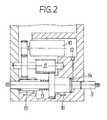
- Fig. 2 einen senkrechten Schnitt durch die Ebene II-II in Fig. 1, und
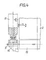
- Fig. 3 und 4 den Werkzeugwechsel in schematischer Form.
- 1a, b the lifting carriage and the swivel arm of the tool changing device with gripper holder and clamping bit shaft in two different views,
- Fig. 2 is a vertical section through the plane II-II in Fig. 1, and
- 3 and 4 the tool change in schematic form.
Die in Fig. 1 dargestellte Werkzeugwechseleinrichtung besteht aus einem Hubschlitten 1, an dem ein Schwenkarm 2 befestigt ist. Der Schwenkarm trägt einen Freiferhalter 4 und wird von der Spannbitwelle 5 durchdrungen.
Der unabhängig von der Werkzeugmaschine operierende Hubschlitten 1 kann ein-, zwei- oder dreiachsig bewegt werden. Der daran befestigte Schwenkarm 2 hat einen quadratischen Querschnitt und ist um die Achse 6 drehbar gelagert. Der Schwenkarm kann Drehbewegungen von 2 x 180°, vorzugsweise 4 x 90° oder in jedem anderen beliebigen Winkel ausführen. Der Antrieb für den Schwenkarm kann vorteilhaft im Hubschlitten integriert werden.
Am unteren Ende des Schwenkarms ist auf einer der vier Seiten in vertikaler Richtung ein um die Achse 7 drehbarer Greiferhalter 4 angebracht. Der Greiferhalter ist mit mindestens vier Werkzeuggreifern 8 ausgerüstet. In der horizontalen Ebene senkrecht zur Achse 7 wird der Schwenkarm von einer motorisch angetriebenen, axial verschiebbaren Spannbitwelle 5 durchdrungen. Die Spannbitwelle hat an beiden Enden ein Profil 9, das Drehmomente übertragen kann.The tool changing device shown in Fig. 1 consists of a
The
At the lower end of the swivel arm, a
In Fig. 2 ist ein Querschnitt durch den unteren Teil des Schwenkarms 2 mit Spannbitwelle 5, dem zugehörigen Antrieb 10, 11 und der Vorrichtung für die Axialbewegung 12, 13 dargestellt.
Der Motor 10 triebt über eine Zwischenwelle 11 die Spannbitwelle 5 an. Der Motor ist vorzugsweise mit einem einstellbaren maximalen Drehmoment für Rechts- und Linkslauf ausgerüstet.
Die Vorrichtung für die Axialbewegungen besteht aus einem Druckluftanschluß 12 und einer Feder 13. Wird der Druckluftanschluß 12 mit Druckluft beaufschlagt, wird die Kammer 14 mit Luft gefüllt und die Spannbitwelle 5 nach links gegen die Kraft der Feder 13 aus dem Schwenkarm 2 herausgedrückt. Hört der Druckluftstrom auf, wird die Spannbitwelle 5 durch die Feder 13 in die gezeichnete Stellung zurückgeschoben. Durch die Endtaster 15 und 16 wird die jeweils gewünschte axiale Stellung der Spannbitwelle festgestellt.2 shows a cross section through the lower part of the
The
The device for the axial movements consists of a compressed air connection 12 and a
Der Werkzeugwechsel mit der erfindungsgemäßen Vorrichtung ist in Fig. 3 und 4 dargestellt.The tool change with the device according to the invention is shown in FIGS. 3 and 4.
Wie in Fig. 3 zu erkennen ist, fährt der Schwenkarm 2 so an die Werkzeugmaschine heran, daß der in dem Werkzeughalter 17 befindliche Werkzeugkopf 18 von dem Greifer 8 gefaßt werden kann. Der Werkzeugkopf ist gespannt. Die Spannbitwelle 5 wird bei langsamer Drehung axial eingekuppelt. Nach erfolgtem Kupplungsvorgang wird mit dem Entspannmoment die Werkzeughalterspannung gelöst.As can be seen in FIG. 3, the
Aus Fig. 4 ist zu erkennen, daß die Spannbitwelle 5 azial aus der Spannstellung ausgekuppelt und der Werkzeugkopf 18 durch axiales Verfahren des Werkzeughalters 17 oder der Greiferplatte 19 vom Werkzeughalter 17 getrennt wird. Der Greiferplatte wird danach gedreht und ein neues Werkzeug in umgekehrten Schritten aufgesetzt und verspannt.From FIG. 4 it can be seen that the
Der besondere Vorteil der vorliegenden Erfindung besteht darin, daß bei Werkzeugwechseleinrichtungen, bei denen sich die Spannschraube der automatischen Spanneinheit in der Werkzeugaufnahme befindet, der Werkzeugwechsel durch einen Schwenkarm ausgeführt werden kann, in dem Greifer- und Spanneinheit integriert sind. Durch diese Vorrichtung kann der Werkzeugwechsel mit einer unabhängig von der Werkzeugmaschine operierenden Einheit vollautomatisch durchgeführt werden.The particular advantage of the present invention is that in tool changing devices in which the clamping screw of the automatic clamping unit is in the tool holder, the tool change can be carried out by a swivel arm in which the gripper and clamping unit are integrated. With this device, the tool change can be carried out fully automatically with a unit that operates independently of the machine tool.
Es ist ein weiterer Vorteil der erfindungsgemäßen Vorrichtung, daß durch die drehbare Lagerung des Schwenkarms, die Schwenkbewegung in jeden beliebigen Winkel erlaubt, sowohl axial als auch radial zur Maschinenachse angeordnete Werkzeugplätze zu erreichen sind. In Verbindung mit der erfindungsgemäß ausgestalteten Spannbitwelle, die es insbesondere ermöglicht sowohl linke als auch rechte Werkzeughalterwechselsysteme zu betätigen, sind damit in der Praxis alle in einer Ebene winkelmäßig unterschiedlich angeordnete Werkzeughaltersysteme bedienbar.It is a further advantage of the device according to the invention that tool positions arranged axially and radially to the machine axis can be achieved by the rotatable mounting of the swivel arm, which allows swivel movement at any angle. In conjunction with the clamping bit shaft designed according to the invention, which in particular makes it possible to operate both left and right tool holder changing systems, in practice all tool holder systems arranged at different angles in one plane can be operated.
Claims (17)
dadurch gekennzeichnet, daß die Werkzeugwechseleinrichtung aus einem Greifer zum Auswechseln des Werkzeugkopfes und aus einer Vorrichtung zum Ein- und Ausspannen des Werkzeugs besteht, die - durch die Integration einer axial verschiebbaren Spannbitwelle - die Bedienung rechter und linker Werkzeughaltersysteme erlaubt und drehbar so gelagert ist, daß Werkzeughalter und Magazinplätze in jeder beliebigen Position bedient werden können.1. Tool changing device for changing and releasing / clamping the tool of tool systems in which the tool head and tool holder are connected by a clamping unit with a clamping screw integrated in the tool holder,
characterized in that the tool changing device consists of a gripper for changing the tool head and a device for clamping and unclamping the tool, which - through the integration of an axially displaceable clamping bit shaft - allows the operation of right and left tool holder systems and is rotatably mounted such that Tool holders and magazine locations can be operated in any position.
Priority Applications (1)
| Application Number | Priority Date | Filing Date | Title |
|---|---|---|---|
| AT88108249T ATE68388T1 (en) | 1987-06-24 | 1988-05-24 | AUTOMATIC TOOL CHANGER. |
Applications Claiming Priority (2)
| Application Number | Priority Date | Filing Date | Title |
|---|---|---|---|
| DE3720805 | 1987-06-24 | ||
| DE19873720805 DE3720805A1 (en) | 1987-06-24 | 1987-06-24 | AUTOMATIC TOOL CHANGE |
Publications (3)
| Publication Number | Publication Date |
|---|---|
| EP0296367A2 true EP0296367A2 (en) | 1988-12-28 |
| EP0296367A3 EP0296367A3 (en) | 1989-03-08 |
| EP0296367B1 EP0296367B1 (en) | 1991-10-16 |
Family
ID=6330168
Family Applications (1)
| Application Number | Title | Priority Date | Filing Date |
|---|---|---|---|
| EP88108249A Expired - Lifetime EP0296367B1 (en) | 1987-06-24 | 1988-05-24 | Automatic tool changer |
Country Status (6)
| Country | Link |
|---|---|
| US (1) | US4860429A (en) |
| EP (1) | EP0296367B1 (en) |
| JP (1) | JPS6416343A (en) |
| AT (1) | ATE68388T1 (en) |
| DE (1) | DE3720805A1 (en) |
| IN (1) | IN168652B (en) |
Families Citing this family (18)
| Publication number | Priority date | Publication date | Assignee | Title |
|---|---|---|---|---|
| JPH07108500B2 (en) * | 1989-09-14 | 1995-11-22 | 第一精機株式会社 | Exchange arm drive controller |
| US5277686A (en) * | 1991-08-21 | 1994-01-11 | Sandvik Ab | Method and device for changing tools in machine tools |
| IT1255767B (en) * | 1992-05-20 | 1995-11-15 | AUTOMATIC TOOL CHANGE DEVICE IN A HEAD OF A PANEL BORING MACHINE | |
| US5896793A (en) * | 1997-04-25 | 1999-04-27 | Ski Industries | Apparatus for feeding bar stock to an automatic screw machine |
| US5911804A (en) * | 1997-09-17 | 1999-06-15 | Ski Industries, Inc. | Method and apparatus for feeding shaped bar stock |
| US5954623A (en) * | 1997-10-07 | 1999-09-21 | Davis; Steven E. | Tool changer apparatus and method of automating a machine tool |
| DE10163294B4 (en) * | 2001-12-21 | 2010-09-09 | Deckel Maho Geretsried Gmbh | Tool change system for program-controlled milling and drilling machines |
| DE10337547A1 (en) * | 2003-08-05 | 2005-03-03 | Ex-Cell-O Gmbh | Tool changing device for a machine tool and method for changing tools on a machine tool |
| DE10336869A1 (en) * | 2003-08-11 | 2005-06-09 | Kennametal Inc. | tool coupling |
| US8277316B2 (en) | 2006-09-14 | 2012-10-02 | Nintendo Co., Ltd. | Method and apparatus for using a common pointing input to control 3D viewpoint and object targeting |
| DE102014105744A1 (en) * | 2014-03-19 | 2015-09-24 | Gebr. Heller Maschinenfabrik Gmbh | Method for tool change |
| CN104128831B (en) * | 2014-07-24 | 2016-09-21 | 肖衍盛 | High-speed motorized spindles automatic tool changer |
| CN107813175A (en) * | 2017-11-30 | 2018-03-20 | 重庆威斯壮智能科技有限公司 | A kind of numer centre cutter mounting frame |
| KR102065854B1 (en) * | 2018-08-30 | 2020-03-02 | 현대위아 주식회사 | Automatic tool changer of machine tool |
| CN111285124B (en) * | 2020-02-19 | 2021-09-10 | 新昌县宏满机械科技有限公司 | Anti-slip cylinder aluminum alloy clamping and stacking device |
| CN112427996A (en) * | 2020-09-27 | 2021-03-02 | 杭州佳菱机械制造有限公司 | Intelligent flexible processing equipment for precision parts |
| CN112518385B (en) * | 2020-12-29 | 2022-03-11 | 安徽圣尔沃智能装备有限公司 | Intelligent adjustment type die casting cutting device |
| DE102021108338A1 (en) | 2021-04-01 | 2022-10-06 | Ott-Jakob Spanntechnik Gmbh | Method for carrying out a tool change and changing device for carrying out the method |
Citations (3)
| Publication number | Priority date | Publication date | Assignee | Title |
|---|---|---|---|---|
| US2654407A (en) * | 1952-08-04 | 1953-10-06 | Albert J Dremel | Motor-driven screw driver |
| EP0125529A2 (en) * | 1983-04-20 | 1984-11-21 | Komet Stahlhalter- und Werkzeugfabrik Robert Breuning GmbH | Tool changing device for a machine tool |
| EP0213399A2 (en) * | 1985-08-31 | 1987-03-11 | Gebrüder Honsberg GmbH | Tool changer |
Family Cites Families (11)
| Publication number | Priority date | Publication date | Assignee | Title |
|---|---|---|---|---|
| US2374919A (en) * | 1943-09-09 | 1945-05-01 | Edward H Bruseth | Milling and drilling adapter for boring bars |
| DD145201B1 (en) * | 1979-07-30 | 1983-06-15 | Ruhla Uhren Veb K | TOOL HOLDING DEVICE ON TOOL MAGAZINES |
| DE3007440A1 (en) * | 1980-02-28 | 1981-09-17 | Fried. Krupp Gmbh, 4300 Essen | TOOL SETUP WITH INTERCHANGEABLE TOOL HOLDER |
| SU1085751A1 (en) * | 1982-10-20 | 1984-04-15 | Ульяновское Головное Специальное Конструкторское Бюро Тяжелых И Фрезерных Станков | Arrangement for securing mandrel in tool carrier |
| GB8330412D0 (en) * | 1983-11-15 | 1983-12-21 | Renishaw Plc | Tool change apparatus |
| JPS60186343A (en) * | 1984-03-02 | 1985-09-21 | Enshu Ltd | Automatic tool replacing device |
| DE3410154A1 (en) * | 1984-03-20 | 1985-10-03 | Fried. Krupp Gmbh, 4300 Essen | TOOL DEVICE WITH INTERCHANGEABLE TOOL HEAD |
| JPS61146444A (en) * | 1984-12-21 | 1986-07-04 | Toshiba Corp | Lathe |
| JPS61168442A (en) * | 1985-01-21 | 1986-07-30 | Toshiba Corp | Lathe |
| DE3532667A1 (en) * | 1985-09-13 | 1987-03-26 | Index Werke Kg Hahn & Tessky | Tool-changing appliance for an industrial robot |
| DE3602247C2 (en) * | 1986-01-25 | 1997-01-23 | Widia Gmbh | Tool coupling for connecting an exchangeable tool head to a tool holder on a machine tool |
-
1987
- 1987-06-24 DE DE19873720805 patent/DE3720805A1/en not_active Withdrawn
-
1988
- 1988-03-30 IN IN268/CAL/88A patent/IN168652B/en unknown
- 1988-05-24 AT AT88108249T patent/ATE68388T1/en active
- 1988-05-24 EP EP88108249A patent/EP0296367B1/en not_active Expired - Lifetime
- 1988-06-21 JP JP63151351A patent/JPS6416343A/en active Pending
- 1988-06-23 US US07/210,564 patent/US4860429A/en not_active Expired - Fee Related
Patent Citations (3)
| Publication number | Priority date | Publication date | Assignee | Title |
|---|---|---|---|---|
| US2654407A (en) * | 1952-08-04 | 1953-10-06 | Albert J Dremel | Motor-driven screw driver |
| EP0125529A2 (en) * | 1983-04-20 | 1984-11-21 | Komet Stahlhalter- und Werkzeugfabrik Robert Breuning GmbH | Tool changing device for a machine tool |
| EP0213399A2 (en) * | 1985-08-31 | 1987-03-11 | Gebrüder Honsberg GmbH | Tool changer |
Non-Patent Citations (1)
| Title |
|---|
| WERKSTATT UND BETRIEB, Band 119, Nr. 9, September 1986, Seiten 797-801, Carl Hanser Verlag, M}nchen, DE; G. SCHEER: "Automatische Werkzeug-Wechselsysteme mit zentraler, radialer Spannkrafteinleitung" * |
Also Published As
| Publication number | Publication date |
|---|---|
| EP0296367A3 (en) | 1989-03-08 |
| DE3720805A1 (en) | 1989-01-05 |
| US4860429A (en) | 1989-08-29 |
| IN168652B (en) | 1991-05-18 |
| EP0296367B1 (en) | 1991-10-16 |
| ATE68388T1 (en) | 1991-11-15 |
| JPS6416343A (en) | 1989-01-19 |
Similar Documents
| Publication | Publication Date | Title |
|---|---|---|
| EP0296367A2 (en) | Automatic tool changer | |
| DE102018103805B4 (en) | ROBOT SYSTEM WITH RECONFIGURABLE END EFFECTOR ASSEMBLY | |
| DE3434009C2 (en) | ||
| EP0742081B1 (en) | Universal precision vice for a machine tool | |
| DE3731280C2 (en) | ||
| EP1841559B1 (en) | Spot welding cap changer | |
| EP3600798B1 (en) | Gripping and positioning assembly for transporting a holding device between different positions | |
| DE3610317A1 (en) | AUTOMATIC CENTERING AND GRIPPING DEVICE | |
| EP3870405B1 (en) | Device for machining a workpiece | |
| DE3438478C2 (en) | Additional handle for portable power tools | |
| DE2830906C2 (en) | Screwing device for screwing in and tightening screws with a high torque | |
| DE3519754C2 (en) | ||
| DE4017351B4 (en) | Automatic machine tool with a support that can be moved in the three Cartesian axes | |
| EP0143257B1 (en) | Tool holding fixture for a punching press, particularly of a turret cutting press for tool changing | |
| DE3634018C2 (en) | ||
| EP0519865A1 (en) | Apparatus for bending wire or the like | |
| EP0255567B1 (en) | Changing tool for a universal drilling and milling machine | |
| DE3226605C2 (en) | ||
| DE3218384A1 (en) | TOOL AND DEVICE FOR RECEIVING AND INSERTING BOLTS OF DIFFERENT LENGTH | |
| EP0355256A2 (en) | Powered chuck for clamping work pieces excentrically | |
| WO1992003253A1 (en) | Clamping device for machine tools | |
| DE3818564C2 (en) | ||
| DE2935381C2 (en) | Device for attaching hinges to a vehicle door. | |
| DE10120009A1 (en) | Tool holding device has third casing able to be clamped between first and second holders | |
| DE4302880A1 (en) | Screwing device with adaptable spindle - has revolving magazine with adaptors for screw bolts or tools and is power driven |
Legal Events
| Date | Code | Title | Description |
|---|---|---|---|
| PUAI | Public reference made under article 153(3) epc to a published international application that has entered the european phase |
Free format text: ORIGINAL CODE: 0009012 |
|
| AK | Designated contracting states |
Kind code of ref document: A2 Designated state(s): AT CH FR GB LI SE |
|
| PUAL | Search report despatched |
Free format text: ORIGINAL CODE: 0009013 |
|
| AK | Designated contracting states |
Kind code of ref document: A3 Designated state(s): AT CH FR GB LI SE |
|
| 17P | Request for examination filed |
Effective date: 19890506 |
|
| 17Q | First examination report despatched |
Effective date: 19901016 |
|
| GRAA | (expected) grant |
Free format text: ORIGINAL CODE: 0009210 |
|
| AK | Designated contracting states |
Kind code of ref document: B1 Designated state(s): AT CH FR GB LI SE |
|
| REF | Corresponds to: |
Ref document number: 68388 Country of ref document: AT Date of ref document: 19911115 Kind code of ref document: T |
|
| GBT | Gb: translation of ep patent filed (gb section 77(6)(a)/1977) | ||
| ET | Fr: translation filed | ||
| PLBE | No opposition filed within time limit |
Free format text: ORIGINAL CODE: 0009261 |
|
| STAA | Information on the status of an ep patent application or granted ep patent |
Free format text: STATUS: NO OPPOSITION FILED WITHIN TIME LIMIT |
|
| 26N | No opposition filed | ||
| PGFP | Annual fee paid to national office [announced via postgrant information from national office to epo] |
Ref country code: GB Payment date: 19930423 Year of fee payment: 6 |
|
| PGFP | Annual fee paid to national office [announced via postgrant information from national office to epo] |
Ref country code: FR Payment date: 19930518 Year of fee payment: 6 |
|
| PGFP | Annual fee paid to national office [announced via postgrant information from national office to epo] |
Ref country code: SE Payment date: 19930526 Year of fee payment: 6 |
|
| PGFP | Annual fee paid to national office [announced via postgrant information from national office to epo] |
Ref country code: AT Payment date: 19930527 Year of fee payment: 6 |
|
| PGFP | Annual fee paid to national office [announced via postgrant information from national office to epo] |
Ref country code: CH Payment date: 19930713 Year of fee payment: 6 |
|
| PG25 | Lapsed in a contracting state [announced via postgrant information from national office to epo] |
Ref country code: GB Effective date: 19940524 Ref country code: AT Effective date: 19940524 |
|
| PG25 | Lapsed in a contracting state [announced via postgrant information from national office to epo] |
Ref country code: SE Effective date: 19940525 |
|
| PG25 | Lapsed in a contracting state [announced via postgrant information from national office to epo] |
Ref country code: LI Effective date: 19940531 Ref country code: CH Effective date: 19940531 |
|
| GBPC | Gb: european patent ceased through non-payment of renewal fee |
Effective date: 19940524 |
|
| EUG | Se: european patent has lapsed |
Ref document number: 88108249.9 Effective date: 19941210 |
|
| PG25 | Lapsed in a contracting state [announced via postgrant information from national office to epo] |
Ref country code: FR Effective date: 19950131 |
|
| REG | Reference to a national code |
Ref country code: CH Ref legal event code: PL |
|
| EUG | Se: european patent has lapsed |
Ref document number: 88108249.9 |
|
| REG | Reference to a national code |
Ref country code: FR Ref legal event code: ST |