EP0355256A2 - Powered chuck for clamping work pieces excentrically - Google Patents
Powered chuck for clamping work pieces excentrically Download PDFInfo
- Publication number
- EP0355256A2 EP0355256A2 EP89106092A EP89106092A EP0355256A2 EP 0355256 A2 EP0355256 A2 EP 0355256A2 EP 89106092 A EP89106092 A EP 89106092A EP 89106092 A EP89106092 A EP 89106092A EP 0355256 A2 EP0355256 A2 EP 0355256A2
- Authority
- EP
- European Patent Office
- Prior art keywords
- clamping
- axis
- jaws
- chuck
- stroke
- Prior art date
- Legal status (The legal status is an assumption and is not a legal conclusion. Google has not performed a legal analysis and makes no representation as to the accuracy of the status listed.)
- Granted
Links
Images


Classifications
-
- B—PERFORMING OPERATIONS; TRANSPORTING
- B23—MACHINE TOOLS; METAL-WORKING NOT OTHERWISE PROVIDED FOR
- B23B—TURNING; BORING
- B23B31/00—Chucks; Expansion mandrels; Adaptations thereof for remote control
- B23B31/02—Chucks
- B23B31/36—Chucks with means for adjusting the chuck with respect to the working-spindle
-
- B—PERFORMING OPERATIONS; TRANSPORTING
- B23—MACHINE TOOLS; METAL-WORKING NOT OTHERWISE PROVIDED FOR
- B23B—TURNING; BORING
- B23B31/00—Chucks; Expansion mandrels; Adaptations thereof for remote control
- B23B31/02—Chucks
- B23B31/10—Chucks characterised by the retaining or gripping devices or their immediate operating means
- B23B31/12—Chucks with simultaneously-acting jaws, whether or not also individually adjustable
-
- Y—GENERAL TAGGING OF NEW TECHNOLOGICAL DEVELOPMENTS; GENERAL TAGGING OF CROSS-SECTIONAL TECHNOLOGIES SPANNING OVER SEVERAL SECTIONS OF THE IPC; TECHNICAL SUBJECTS COVERED BY FORMER USPC CROSS-REFERENCE ART COLLECTIONS [XRACs] AND DIGESTS
- Y10—TECHNICAL SUBJECTS COVERED BY FORMER USPC
- Y10T—TECHNICAL SUBJECTS COVERED BY FORMER US CLASSIFICATION
- Y10T279/00—Chucks or sockets
- Y10T279/14—Eccentric
-
- Y—GENERAL TAGGING OF NEW TECHNOLOGICAL DEVELOPMENTS; GENERAL TAGGING OF CROSS-SECTIONAL TECHNOLOGIES SPANNING OVER SEVERAL SECTIONS OF THE IPC; TECHNICAL SUBJECTS COVERED BY FORMER USPC CROSS-REFERENCE ART COLLECTIONS [XRACs] AND DIGESTS
- Y10—TECHNICAL SUBJECTS COVERED BY FORMER USPC
- Y10T—TECHNICAL SUBJECTS COVERED BY FORMER US CLASSIFICATION
- Y10T279/00—Chucks or sockets
- Y10T279/18—Pivoted jaw
-
- Y—GENERAL TAGGING OF NEW TECHNOLOGICAL DEVELOPMENTS; GENERAL TAGGING OF CROSS-SECTIONAL TECHNOLOGIES SPANNING OVER SEVERAL SECTIONS OF THE IPC; TECHNICAL SUBJECTS COVERED BY FORMER USPC CROSS-REFERENCE ART COLLECTIONS [XRACs] AND DIGESTS
- Y10—TECHNICAL SUBJECTS COVERED BY FORMER USPC
- Y10T—TECHNICAL SUBJECTS COVERED BY FORMER US CLASSIFICATION
- Y10T279/00—Chucks or sockets
- Y10T279/19—Radially reciprocating jaws
- Y10T279/1973—Wedge actuated
-
- Y—GENERAL TAGGING OF NEW TECHNOLOGICAL DEVELOPMENTS; GENERAL TAGGING OF CROSS-SECTIONAL TECHNOLOGIES SPANNING OVER SEVERAL SECTIONS OF THE IPC; TECHNICAL SUBJECTS COVERED BY FORMER USPC CROSS-REFERENCE ART COLLECTIONS [XRACs] AND DIGESTS
- Y10—TECHNICAL SUBJECTS COVERED BY FORMER USPC
- Y10T—TECHNICAL SUBJECTS COVERED BY FORMER US CLASSIFICATION
- Y10T279/00—Chucks or sockets
- Y10T279/24—Chucks or sockets by centrifugal force
- Y10T279/243—Chucks or sockets by centrifugal force to counterbalance jaws
-
- Y—GENERAL TAGGING OF NEW TECHNOLOGICAL DEVELOPMENTS; GENERAL TAGGING OF CROSS-SECTIONAL TECHNOLOGIES SPANNING OVER SEVERAL SECTIONS OF THE IPC; TECHNICAL SUBJECTS COVERED BY FORMER USPC CROSS-REFERENCE ART COLLECTIONS [XRACs] AND DIGESTS
- Y10—TECHNICAL SUBJECTS COVERED BY FORMER USPC
- Y10T—TECHNICAL SUBJECTS COVERED BY FORMER US CLASSIFICATION
- Y10T279/00—Chucks or sockets
- Y10T279/25—Compensation for eccentricity
Definitions
- the invention relates to a power-operated jaw chuck for workpieces to be eccentrically clamped, in particular crankshafts, the clamping axis running parallel and eccentrically to the axis of rotation of the chuck, with a chuck base which can be fastened coaxially to the axis of rotation on a lathe spindle, one on the chuck base parallel to that through the axis of rotation and the Clamping axis that goes along the center axis and that allows the adjustment of the eccentricity of the clamping axis relative to the axis of rotation, in which in a mirror-symmetrical arrangement to the center plane, two circular arcs bent around axes of curvature parallel to the clamping axis and adjustable by pivoting about their axis of curvature against the clamping axis are guided to actuate them an axially adjustable drive member is provided in the chuck base, and with one in the central plane and in relation to the clamping axis with respect to the clamping heads of the arcuate S jaw
- the counter bearing is a fixed support for the workpiece on the clamping head.
- the invention has for its object to design a chuck of the type mentioned so that the workpiece experiences a central clamping and therefore tolerances of the workpiece in the clamping diameter can not lead to corresponding tolerances in the eccentricity of the clamping axis with respect to the axis of rotation.
- the counterbearing is designed as a central clamping jaw driven centrally in the clamping stroke with the two circular arc-shaped clamping jaws and is guided in the clamping head in the central plane and in relation to the clamping axis in a radially adjustable manner, and that for the common adjustment of all three clamping jaws, an actuating piston which is connected to the drive member and is axially guided in the clamping head is provided, which has a clamping wedge body, against which the clamping jaws rest over their own clamping surfaces which are inclined to the clamping axis.
- a preferred embodiment is characterized in that the clamping wedge body has two lateral clamping surfaces for the ends of the circular arc-shaped clamping jaws which abut them with corresponding inclined surfaces and in the middle therebetween a groove-like recess in which the central clamping jaw runs and on the groove side walls of which spline teeth are provided which are provided in driving grooves grasp the sides of the central clamping jaw and carry the clamping surfaces assigned to this clamping jaw, which the clamping jaw rests with the corresponding oblique side walls of the driving grooves.
- the clamping jaws all have a thickness which is substantially the same in the axial direction and can be arranged perpendicular to the axial direction in essentially the same plane.
- This arrangement of all the clamping jaws, including their clamping surfaces, in essentially the same plane results in a reaction-free clamping process, so that the clamping jaws cannot "beak open" when the workpiece is clamped.
- the central clamping jaw with its actuating device does not build axially larger than the circular-arc-shaped clamping jaws, which overall allows a short axial chuck length.
- the actuating piston can then perform a rapid stroke only for the two circular-shaped clamping jaws for completely opening the workpiece holder after the clamping stroke of all clamping jaws, the clamping wedge body only on the way of the clamping stroke with the central clamping jaw is engaged on the path of Schnellhubes is unhooked from this clamping jaw, and that the actuating piston overlaps the ends of the arcuate clamping jaws, each with an extension arm, on which there is a projection which engages in an inclined groove inclined to the clamping axis, the length of which is equal to the travel sum of the clamping and rapid strokes , whereby the inclination of the oblique groove is chosen in the same sense as that of the clamping surface.
- the circular jaws perform the closing movement of the clamping stroke over the clamping surfaces, but the opening movement of the clamping stroke and both the closing and the opening movement of the quick stroke via the projections engaging in the oblique grooves.
- the circular jaws can be adjusted back so far that the workpiece can be inserted from the side between the two jaws into the chuck or removed from it again.
- the middle clamping jaw suspended from the clamping wedge body during the rapid stroke can have an adjustment limitation which limits the adjustments of the suspended clamping lacquers to such an extent that the coupling between the clamping jaw and clamping wedge body takes place during the subsequent clamping stroke.
- the spline teeth are provided with run-in bevels at their end entering the driving grooves.
- the arrangement will be such that the inclination of the oblique groove is less on the path corresponding to the clamping stroke than on the path corresponding to the rapid stroke. It is also to be ensured that, if necessary, the clamping wedge body has cutouts which have the ends of the circular jaws when these jaws are in the fully open position at the end of the rapid stroke. The clamping wedge body can then not hinder the adjustment of the circular jaws in the fully open position.
- the arrangement of all three clamping jaws in essentially the same level is further associated with the advantage that space is available behind this level for further adjustment devices, such as for straightening jaws, etc.
- adjusting devices and locking devices for the counterweights can be arranged axially behind the guide plane for the clamping jaws in the case of counterweights which are displaceably guided on the clamping head for balancing the unbalance.
- the adjusting devices for the clamping head guided on the chuck base are preferably arranged in the same plane as the adjusting and fixing devices for the counterweights, the adjusting devices for the counterweights on the one hand and the clamping head on the other hand being arranged diametrically opposite one another and in the central plane on the clamping head. Therefore, the eccentric stroke between the clamping axis and the axis of rotation on the one hand and the counterweights on the other hand can be set independently of one another, which enables the compensation of different workpiece weights with the same eccentricity.
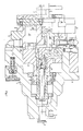
- the jaw chuck is used for eccentric clamping of crankshafts, the axially seen outline of which is indicated at 1.
- the clamping axis 2 runs parallel and eccentrically to the axis of rotation 3 of the chuck.
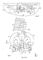
- the chuck itself consists in its basic structure of a coaxial to the axis of rotation 3 attachable to a lathe spindle, not shown Chuck base 4, a clamping head 5 with clamping jaws 6, 7, which is displaceably held on the chuck base parallel to the central plane passing through the axis of rotation 3 and the clamping axis 2 and enables the eccentricity of the clamping axis 2 to be adjusted with respect to the axis of rotation 3, and also with the unbalance of the clamping head 5 balancing counterweights 8, which are guided on the clamping head 5 in the same adjustment direction as this, and from straightening jaws 9, with which the workpiece 1 can be pre-aligned before it is clamped between the clamping jaws 6, 7.
- the clamping jaws 6, 7 are guided in the clamping head 5, namely, first of all, there are two clamping jaws 6, which are arranged mirror-symmetrically to the central plane, are curved in a circular arc around curvature axes 10 parallel to the clamping axis 2 and are adjustable by pivoting about their curvature axis 10 against the clamping axis 2, as well as a central clamping jaw 7, which is driven centrally in the clamping stroke with the two arcuate clamping jaws 6 and which is guided so as to be radially adjustable in relation to the clamping heads 41 of the clamping jaws 6 in the central plane and in relation to the clamping axis 2.
- a drive member 11 is axially adjustable in the chuck base 4, to which an actuating piston 12, which is axially guided in the clamping head 4 and has a clamping wedge body 13, is connected, the clamping jaws 6, 7 each having their own, oblique Clamping surfaces 14, 15 are inclined to the clamping axis 2.
- An actuating member 15 for the straightening jaws 9 is nested in the chuck base 4 in the drive member 11 for the clamping jaws 6, 7, on which actuating bolts 16, which are displaceable in the clamping head 5, are suspended in the same direction as the clamping head 5 axially guided and are formed at their front end with a wedge head 17 which engage in a corresponding wedge receptacle 18 of the straightening jaws 9.
- the connection of the tip 20 or the straightening jaws 9 to their respective actuators 15, 19 cannot hinder the displacement of the clamping head 5 on the chuck base 4.
- the actuating piston 12 is suspended on the driving member 11 for the clamping jaws 6, 7, so that the actuating piston 12 together with the clamping head 5 can move relative to the chuck base 4 and the driving member 11, if that has a yoke 22 on the chuck base 4 mounted adjusting spindle 23 is rotated, which engages in a nut 24 provided with bush 24 of the clamping head 5.
- an externally rotatable shaft 25 with a gear 26 is mounted in the clamping head 5 diametrically opposite the adjusting spindle 23, which meshes with intermediate gears 26 'with a spindle 27 also mounted in the clamping head 5, which in the counterweights 8 engages in a nut thread 28. If the adjusting spindle 23 and the gear shaft 25 are rotated as a result, the clamping head 5 or the counterweights 8 are adjusted parallel to one another.
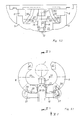
- the clamping wedge body 13 has two lateral clamping surfaces 14 for the corresponding sloping surfaces 14 'adjacent ends of the circular arc-shaped clamping jaws 6 and centrally between them a groove-like recess 31 in which the central clamping jaw 7 runs.
- the path of all clamping jaws 6, 7 during the clamping stroke can be adjusted exactly to one another and coordinated with one another, so that there is a central clamping movement of all three clamping jaws related to the clamping axis 2 6, 7 results.
- the actuating piston 12 can then perform a quick stroke for the clamping stroke of all clamping jaws 6, 7 only for the two circular-shaped clamping jaws 6, in order to open these circular-shaped clamping jaws completely for the tool holder, so that the tool can be seen from the side between the open circular-curved clamping jaws 6 the chuck can be inserted.
- the clamping wedge body 13 engages only on the way of the clamping stroke, but on the way of the quick stroke it is detached from this clamping jaw 7, as the comparison of FIG. 4.3 and 5.3 can be recognized immediately.
- the middle clamping jaw 7 In order to prevent the unhooked condition that the middle clamping jaw 7 executes independent movements which could subsequently prevent the wedge teeth 32 from re-entering the driving groove 33 during the clamping stroke, the movement of the middle clamping jaw 7 is limited, for which purpose a stop screw 34 in FIG. 1 on the central clamping jaw 7 engages in a limiting groove 35 provided in the clamping head 5.
- the spline teeth 32 are provided with run-in bevels 36 at their end leading into the driving grooves 33.
- the opening stroke of the clamping stroke and the closing and opening stroke of the quick stroke do not take place for the circular jaws 6 over the clamping surfaces 14, rather the actuating piston 12 overlaps the ends of the circular jaws 6, each with an arm 37, on which a projection 38 in the form of a Bolt is located, which engages in an inclined groove 39 inclined to the clamping axis 2, the length of which is equal to the travel sum of the clamping and rapid stroke, the inclination of the inclined groove 39 being chosen in the same sense as that of the clamping surface 14 and along the path 39.1 corresponding to the clamping stroke is less than on the path 39.2 corresponding to the rapid stroke.
- the clamping wedge body 13 has recesses 40 which accommodate the ends of the circular clamping jaws 6 when these jaws 6 are in the fully open position at the end of overdrive. The complete opening of the circular jaws 6 is thus not hindered by the clamping wedge body 13.
- the clamping jaws 6, 7 all have the same thickness in the axial direction and are arranged perpendicular to the axial direction in essentially the same plane. You can not beak open during the clamping process, so that a reaction-free central clamping of the workpiece 1 is ensured.
Abstract
Das Backenspannfutter besitzt eine koaxial zur Drehachse (3) auf einer Drehmaschinenspindel befestigbare Futterbasis (4), einen an der Futterbasis parallel zu der durch die Drehachse (3) und die Spannachse (2) gehenden Mittelebene verschiebbar gehaltenen und die Einstellung der Exzentrizität der Spannachse (2) gegenüber der Drehachse (3) ermöglichenden Spannkopf (5), in dem in zur Mittelebene spiegelsymmetrischer Anordnung zwei kreisbogenförmig um zur Spannachse parallele Krümmungsachsen (10) gebogene und durch Schwenken um ihre Krümmungsachse gegen die Spannachse (2) verstellbare Spannbacken (6) geführt sind und eine in der Mittelebene und in Bezug auf die Spannachse gegenüber den Spannkopfen (41) der kreisbogenförmigen Spannbacken (6) angeordnete mittlere Spannbacke (7), die im Spannhub zentrisch mit den beiden kreisbogenförmigen Spannbacken (6) in der Mittelebene und in Bezug auf die Spannachse (2) radial verstellbar geführt ist. Zur gemeinsamen Verstellung aller drei Spannbacken (6, 7) ist ein im Spannkopf (5) axial geführter Betätigungskolben (12) vorgesehen ist, der einen Spannkeilkörper aufweist, dem die Spannbacken (6, 7) über jeweils eigene, schräg zur Spannachse (2) geneigt verlaufende Spannflächen anliegen.The jaw chuck has a chuck base (4) that can be fastened coaxially to the axis of rotation (3) on a lathe spindle, a chuck base that is held on the chuck base parallel to the central plane passing through the axis of rotation (3) and the clamping axis (2), and the setting of the eccentricity of the clamping axis ( 2) Compared to the axis of rotation (3), the clamping head (5), in which in a mirror-symmetrical arrangement to the central plane, two clamping arches (10) bent in a circular arc around the axes of curvature parallel to the clamping axis and adjustable by pivoting about their axis of curvature against the clamping axis (2), are guided and a central clamping jaw (7) arranged in the central plane and with respect to the clamping axis opposite the clamping heads (41) of the circular arc-shaped clamping jaws (6), which is centered in the clamping stroke with the two circular arc-shaped clamping jaws (6) in the central plane and in relation to the clamping axis (2) is radially adjustable. For the joint adjustment of all three clamping jaws (6, 7) an actuating piston (12) axially guided in the clamping head (5) is provided, which has a clamping wedge body to which the clamping jaws (6, 7) each have their own, inclined to the clamping axis (2) inclined clamping surfaces.
Description
Die Erfindung betrifft ein kraftbetätigtes Backenspannfutter für exzentrisch zu spannende Werkstücke, insbesondere Kurbelwellen, wobei die Spannachse parallel und exzentrisch zur Drehachse des Spannfutters verläuft, mit einer koaxial zur Drehachse auf einer Drehmaschinenspindel befestigbaren Futterbasis, einem an der Futterbasis parallel zu der durch die Drehachse und die Spannachse gehenden Mittelebene verschiebbar gehaltenen und die Einstellung der Exzentrizität der Spannachse gegenüber der Drehachse ermöglichenden Spannkopf, in dem in zur Mittelebene spiegelsymmetrischer Anordnung zwei kreisbogenförmig um zur Spannachse parallele Krümmungsachsen gebogene und durch Schwenken um ihre Krümmungsachse gegen die Spannachse verstellbare Spannbacken geführt sind, zu deren Betätigung ein in der Futterbasis axial verstellbar angeordnetes Treibglied vorgesehen ist, und mit einem in der Mittelebene und in Bezug auf die Spannachse gegenüber den Spannköpfen der kreisbogenförmigen Spannbacken angeordneten Gegenlager für das Werkstück.The invention relates to a power-operated jaw chuck for workpieces to be eccentrically clamped, in particular crankshafts, the clamping axis running parallel and eccentrically to the axis of rotation of the chuck, with a chuck base which can be fastened coaxially to the axis of rotation on a lathe spindle, one on the chuck base parallel to that through the axis of rotation and the Clamping axis that goes along the center axis and that allows the adjustment of the eccentricity of the clamping axis relative to the axis of rotation, in which in a mirror-symmetrical arrangement to the center plane, two circular arcs bent around axes of curvature parallel to the clamping axis and adjustable by pivoting about their axis of curvature against the clamping axis are guided to actuate them an axially adjustable drive member is provided in the chuck base, and with one in the central plane and in relation to the clamping axis with respect to the clamping heads of the arcuate S jaws for the workpiece.
Bei bekannten Spannfuttern dieser Art ist das Gegenlager ein am Spannkopf feststehendes Auflager für das Werkstück. Das hat zur Folge, daß vor der Bearbeitung bestehende Toleranzen des Werkstückes im Spanndurchmesser bei der Einspannung zwischen dem festen Auflager und den beiden kreisbogenförmigen Spannbacken zu entsprechenden Unterschieden im Exzenterhub zwischen der Spannachse und der Drehachse führen, so daß auch die Exzentrizität des im Spannfutter fertig bearbeiteten Werkstücks entsprechende Toleranzen zeigt.In known chucks of this type, the counter bearing is a fixed support for the workpiece on the clamping head. As a result, existing ones exist before processing Tolerances of the workpiece in the clamping diameter during the clamping between the fixed support and the two circular arc-shaped clamping jaws lead to corresponding differences in the eccentric stroke between the clamping axis and the axis of rotation, so that the eccentricity of the workpiece finished in the chuck also shows corresponding tolerances.
Der Erfindung liegt die Aufgabe zugrunde, ein Spannfutter der eingangs genannten Art so auszubilden, daß das Werkstück eine zentrische Einspannung erfährt und daher Toleranzen des Werkstücks im Spanndurchmesser nicht zu entsprechenden Toleranzen in der Exzentrizität der Spannachse gegenüber der Drehachse führen können.The invention has for its object to design a chuck of the type mentioned so that the workpiece experiences a central clamping and therefore tolerances of the workpiece in the clamping diameter can not lead to corresponding tolerances in the eccentricity of the clamping axis with respect to the axis of rotation.
Diese Aufgabe wird nach der Erfindung dadurch gelöst, daß das Gegenlager als eine im Spannhub zentrisch mit den beiden kreisbogenförmigen Spannbacken angetriebene mittlere Spannbacke ausgebildet und dazu in der Mittelebene und in Bezug auf die Spannachse radial verstellbar im Spannkopf geführt ist, und daß zur gemeinsamen Verstellung aller drei Spannbacken ein an das Treibglied angeschlossener, im Spannkopf axial geführter Betätigungskolben vorgesehen ist, der einen Spannkeilkörper aufweist, dem die Spannbacken über jeweils eigene, schräg zur Spannachse geneigt verlaufende Spannflächen anliegen.This object is achieved according to the invention in that the counterbearing is designed as a central clamping jaw driven centrally in the clamping stroke with the two circular arc-shaped clamping jaws and is guided in the clamping head in the central plane and in relation to the clamping axis in a radially adjustable manner, and that for the common adjustment of all three clamping jaws, an actuating piston which is connected to the drive member and is axially guided in the clamping head is provided, which has a clamping wedge body, against which the clamping jaws rest over their own clamping surfaces which are inclined to the clamping axis.
Dadurch wird erreicht, daß alle drei Spannbacken zentrisch auf die Spannachse spannen, wobei die Spannwege der Spannbacken über die Neigung der Spannflächen genau aufeinander abgestimmt werden können.It is thereby achieved that all three clamping jaws clamp centrally on the clamping axis, the clamping paths of the clamping jaws being able to be precisely coordinated with one another via the inclination of the clamping surfaces.
Eine bevorzugte Ausführungsform ist dadurch gekennzeichnet, daß der Spannkeilkörper zwei seitliche Spannflächen für die ihnen mit entsprechenden Schrägflächen anliegenden Enden der kreisbogenförmigen Spannbacken und mittig dazwischen eine nutartige Aussparung aufweist, in der die mittlere Spannbacke verläuft und an deren Nutseitenwände Keilzähne vorgesehen sind, die in Treibnuten an den Seiten der mittleren Spannbacke greifen und die dieser Spannbacke zugeordneten Spannflächen tragen, welchen die Spannbacke mit den entsprechenden schrägen Seitenwänden der Treibnuten anliegt.A preferred embodiment is characterized in that the clamping wedge body has two lateral clamping surfaces for the ends of the circular arc-shaped clamping jaws which abut them with corresponding inclined surfaces and in the middle therebetween a groove-like recess in which the central clamping jaw runs and on the groove side walls of which spline teeth are provided which are provided in driving grooves grasp the sides of the central clamping jaw and carry the clamping surfaces assigned to this clamping jaw, which the clamping jaw rests with the corresponding oblique side walls of the driving grooves.
Der damit verbundene Vorteil besteht darin, daß die Spannbacken alle in axialer Richtung im wesentlichen übereinstimmende Dicke aufweisen und senkrecht zur Axialrichtung in im wesentlichen derselben Ebene angeordnet sein können. Diese Anordnung aller Spannbacken einschließlich ihrer Spannflächen in im wesentlichen derselben Ebene ergibt einen reaktionsfreien Spannvorgang, so daß die Spannbacken beim Einspannen des Werkstücks nicht "aufschnäbeln" können. Außerdem baut die mittlere Spannbacke mit ihrer Betätigungseinrichtung axial nicht größer als die kreisbogenförmigen Spannbacken, was insgesamt eine kurze axiale Futterbaulänge ermöglicht.The advantage associated with this is that the clamping jaws all have a thickness which is substantially the same in the axial direction and can be arranged perpendicular to the axial direction in essentially the same plane. This arrangement of all the clamping jaws, including their clamping surfaces, in essentially the same plane results in a reaction-free clamping process, so that the clamping jaws cannot "beak open" when the workpiece is clamped. In addition, the central clamping jaw with its actuating device does not build axially larger than the circular-arc-shaped clamping jaws, which overall allows a short axial chuck length.
Im einzelnen empfiehlt es sich, die Anordnung so zu treffen, daß der Betätigungskolben anschließend an den Spannhub aller Spannbacken einen Schnellhub nur für die beiden kreisbogenförmigen Spannbacken zum vollständigen Öffnen der Werkstückaufnahme ausführen kann, wobei der Spannkeilkörper nur auf dem Wege des Spannhubes mit der mittleren Spannbacke im Eingriff steht, auf dem Weg des Schnellhubes aber aus dieser Spannbacke ausgehängt ist, und daß der Betätigungskolben die Enden der kreisbogenförmigen Spannbacken mit je einem Ausleger übergreift, an dem sich ein Vorsprung befindet, der in eine zur Spannachse geneigte Schrägnut greift, deren Länge gleich der Wegsumme von Spann- und Schnellhub ist, wobei die Neigung der Schrägnut im gleichen Sinn wie die der Spannfläche gewählt ist.Specifically, it is advisable to make the arrangement so that the actuating piston can then perform a rapid stroke only for the two circular-shaped clamping jaws for completely opening the workpiece holder after the clamping stroke of all clamping jaws, the clamping wedge body only on the way of the clamping stroke with the central clamping jaw is engaged on the path of Schnellhubes is unhooked from this clamping jaw, and that the actuating piston overlaps the ends of the arcuate clamping jaws, each with an extension arm, on which there is a projection which engages in an inclined groove inclined to the clamping axis, the length of which is equal to the travel sum of the clamping and rapid strokes , whereby the inclination of the oblique groove is chosen in the same sense as that of the clamping surface.
Im Ergebnis vollführen die kreisbogenförmigen Spannbacken die Schließbewegung des Spannhubs über die Spannflächen, die Öffnungsbewegung des Spannhubs aber und sowohl die Schließ- als auch die Öffnungsbewegung des Schnellhubes über die in die Schrägnuten eingreifenden Vorsprünge. Mit Hilfe des Schnellhubs können die kreisförmigen Spannbacken soweit zurückverstellt werden, daß das Werkstück von der Seite her zwischen den beiden Spannbacken hindurch in das Spannfutter eingelegt bzw. ihm wieder entnommen werden kann. Die mittlere und während des Schnellhubs vom Spannkeilkörper abgehängte Spannbacke kann eine Verstellbegrenzung aufweisen, die Verstellungen der ausgehängten Spannlacke soweit begrenzt, daß beim anschließenden Spannhub die Einkupplung zwischen Spannbacke und Spannkeilkörper zwanglos erfolgt. Dazu kann es sich empfehlen, daß die Keilzähne an ihrem in die Treibnuten voran einlaufenden Ende mit Einlaufschrägen versehen sind.As a result, the circular jaws perform the closing movement of the clamping stroke over the clamping surfaces, but the opening movement of the clamping stroke and both the closing and the opening movement of the quick stroke via the projections engaging in the oblique grooves. With the help of the rapid stroke, the circular jaws can be adjusted back so far that the workpiece can be inserted from the side between the two jaws into the chuck or removed from it again. The middle clamping jaw suspended from the clamping wedge body during the rapid stroke can have an adjustment limitation which limits the adjustments of the suspended clamping lacquers to such an extent that the coupling between the clamping jaw and clamping wedge body takes place during the subsequent clamping stroke. For this purpose, it can be recommended that the spline teeth are provided with run-in bevels at their end entering the driving grooves.
Im übrigen wird man die Anordnung so treffen, daß die Neigung der Schrägnut auf dem den Spannhub entsprechenden Weg geringer als auf dem den Schnellhub entsprechenden Weg ist. Auch ist dafür zu sorgen, daß erforderlichenfalls der Spannkeilkörper Freisparungen aufweist, welche die Enden der kreisförmigen Spannbacken aufnehmen, wenn diese Spannbacken am Ende des Schnellhubs in der voll geöffneten Stellung stehen. Der Spannkeilkörper kann dann die Verstellung der kreisbogenförmigen Spannbacken in die vollständig geöffnete Stellung nicht behindern.Otherwise, the arrangement will be such that the inclination of the oblique groove is less on the path corresponding to the clamping stroke than on the path corresponding to the rapid stroke. It is also to be ensured that, if necessary, the clamping wedge body has cutouts which have the ends of the circular jaws when these jaws are in the fully open position at the end of the rapid stroke. The clamping wedge body can then not hinder the adjustment of the circular jaws in the fully open position.
Die Anordnung aller drei Spannbacken in im wesentlichen derselben Ebene ist weiter mit dem Vorteil verbunden, daß hinter dieser Ebene Raum für weitere Verstelleinrichtungen, wie für Richtbacken usw., zur Verfügung steht. Insbesondere ist es vorteilhaft, daß bei am Spannkopf zum Unwuchtausgleich verschiebbar geführten Gegengewichten Verstelleinrichtungen und Feststelleinrichtungen für die Gegengewichte axial hinter der Führungsebene für die Spannbacken angordnet sein können. Vorzugsweise sind die Verstelleinrichtungen für den an der Futterbasis geführten Spannkopf in derselben Ebene wie die Ver- und Feststelleinrichtungen für die Gegengewichte angeordnet, wobei die Verstelleinrichtungen für die Gegengewichte einerseits und den Spannkopf andererseits einander diametral gegenüber und in der Mittelebene am Spannkopf angeordnet sind. Daher können der Exzenterhub zwischen der Spannachse und der Drehachse einerseits und die Gegengewichte andererseits unabhängig voneinander eingestellt werden, was den Ausgleich unterschiedlicher Werkstückgewichte bei gleicher Exzentrizität ermöglicht.The arrangement of all three clamping jaws in essentially the same level is further associated with the advantage that space is available behind this level for further adjustment devices, such as for straightening jaws, etc. In particular, it is advantageous that adjusting devices and locking devices for the counterweights can be arranged axially behind the guide plane for the clamping jaws in the case of counterweights which are displaceably guided on the clamping head for balancing the unbalance. The adjusting devices for the clamping head guided on the chuck base are preferably arranged in the same plane as the adjusting and fixing devices for the counterweights, the adjusting devices for the counterweights on the one hand and the clamping head on the other hand being arranged diametrically opposite one another and in the central plane on the clamping head. Therefore, the eccentric stroke between the clamping axis and the axis of rotation on the one hand and the counterweights on the other hand can be set independently of one another, which enables the compensation of different workpiece weights with the same eccentricity.
Im folgenden wird die Erfindung an einem in der Zeichnung dargestellten Ausführungsbeispiel näher erläutert; es zeigen:
- Fig. 1 einen Axialschnitt durch ein Backenspannfutter nach der Erfindung,
- Fig. 2 eine Ansicht des Spannfutters nach Fig. 1 von vorn bei entferntem Futterdeckel und teilweise im Schnitt,
- Fig. 3 den Schnitt III - III in Fig. 2,
- Fig. 4.1 bis 4.3 eine Einzeldarstellung der für die Erfindung wesentlichsten Teile, nämlich der Spannbacken und des Befestigungskolbens mit dem Spannkeilkörper in der Schließstellung der Spannbacken, und zwar in Fig. 4.1 in einer Axialansicht, in Fig. 4.2 den Schnitt IV.2 - IV.2 in Fig. 4.1 und in Fig. 4.3 den Schnitt IV.3 IV.3 in Fig. 4.1,
- Fig. 5.1 bis 5.3 den Gegenstand der Fig. 4.1 bis 4.3 in der Offenstellung der Spannbacken,
- Fig. 6 den Schnitt VI - VI in Fig. 4.1 und
- Fig. 7 eine Einzeldarstellung des Betätigungskolbens mit dem Spannkeilkörper in einer Schrägansicht.
- 1 is an axial section through a jaw chuck according to the invention,
- 2 is a view of the chuck of FIG. 1 from the front with the chuck cover removed and partially in section,
- 3 shows the section III - III in FIG. 2,
- 4.1 to 4.3 an individual representation of the parts essential to the invention, namely the clamping jaws and the fastening piston with the clamping wedge body in the closed position of the clamping jaws, specifically in FIG. 4.1 in an axial view, in FIG. 4.2 the section IV.2 - IV .2 in Fig. 4.1 and in Fig. 4.3 the section IV.3 IV.3 in Fig. 4.1,
- 5.1 to 5.3 the subject of FIGS. 4.1 to 4.3 in the open position of the jaws,
- Fig. 6 shows the section VI - VI in Fig. 4.1 and
- Fig. 7 is an individual view of the actuating piston with the clamping wedge body in an oblique view.
Das Backenspannfutter dient zum exzentrischen Spannen von Kurbelwellen, deren axial gesehener Umriß bei 1 angedeutet ist. Bei diesen Werkstücken verläuft die Spannachse 2 parallel und exzentrisch zur Drehachse 3 des Spannfutters. Das Spannfutter selbst besteht seinem grundsätzlichen Aufbau nach aus einer koaxial zur Drehachse 3 auf einer nicht dargestellten Drehmaschinenspindel befestigbaren Futterbasis 4, einem an der Futterbasis parallel zu der durch die Drehachse 3 und die Spannachse 2 gehenden Mittelebene verschiebbar gehaltenen und die Einstellung der Exzentrizität der Spannachse 2 gegenüber der Drehachse 3 ermöglichenden Spannkopf 5 mit Spannbacken 6, 7, ferner mit die Unwucht des Spannkopfes 5 ausgleichenden Gegengewichten 8, die am Spannkopf 5 in gleicher Verstellrichtung wie dieser geführt sind, und aus Richtbacken 9, mit welchen eine Vorausrichtung des Werkstücks 1 vor seiner Spannung zwischen den Spannbacken 6, 7 möglich ist. Die Spannbacken 6, 7 sind im Spannkopf 5 geführt, und zwar handelt es sich zunächst um zwei spiegelsymmetrisch zur Mittelebene angeordnete, kreisbogenförmig um zur Spannachse 2 parallele Krümmungsachsen 10 gebogene und durch Schwenken um ihre Krümmungsachse 10 gegen die Spannachse 2 verstellbare Spannbacken 6, sowie um eine im Spannhub zentrisch mit den beiden kreisbogenförmigen Spannbacken 6 angetriebene mittlere Spannbacke 7, die gegenüber den Spannköpfen 41 der Spannbacken 6 in der Mittelebene und in Bezug auf die Spannachse 2 radial verstellbar geführt ist. Zur Betätigung aller drei Spannbacken 6, 7 ist in der Futterbasis 4 axial verstellbar ein Treibglied 11 angeordnet, an das ein im Spannkopf 4 axial geführter Betätigungskolben 12 angeschlossen ist, der einen Spannkeilkörper 13 aufweist, em die Spannbacken 6, 7 über jeweils eigene, schräg zur Spannachse 2 geneigt verlaufende Spannflächen 14, 15 anliegen. In das Treibglied 11 für die Spannbacken 6, 7 liegt eingeschachtelt in der Futterbasis 4 ein Betätigungsglied 15 für die Richtbacken 9, an dem in gleicher Richtung wie der Spannkopf 5 verschiebbar Betätigungsbolzen 16 eingehängt sind, die im Spannkopf 5 axial geführt und an ihrem vorderen Ende mit einem Keilkopf 17 ausgebildet sind, welche in eine entsprechende Keilaufnahmen 18 der Richtbacken 9 greifen. Eingeschachtelt in das Betätigungsglied 15 für die Richtbacken 9 wiederum liegt ein Betätigungsglied 19 für eine in der Spannachse 2 liegende Spitze 20, wobei die Spitze 20 ebenfalls verschiebbar am Betätigungsglied 19 eingehängt ist. Im Ergebnis kann der Anschluß der Spitze 20 bzw. der Richtbacken 9 an ihren jeweiligen Betätigungsgliedern 15, 19 das Verschieben des Spannkopfes 5 an der Futterbasis 4 nicht behindern. Entsprechend verschiebbar über eine T-Nutverbindung 21 ist am Treibglied 11 für die Spannbacken 6, 7 der Betätigungskolben 12 eingehängt, so daß sich der Betätigungskolben 12 zusammen mit dem Spannkopf 5 gegenüber der Futterbasis 4 und dem Treibglied 11 verschieben kann, wenn die über ein Joch 22 an der Futterbasis 4 gelagerte Verstellspindel 23 gedreht wird, die in eine mit Muttergewinde versehene Büchse 24 des Spannkopfes 5 greift. - Für die Verstellung der Gegengewichte 8 ist im Spannkopf 5 diametral gegenüber der Verstellspindel 23 ein von außen drehbarer Schaft 25 mit einem Zahnrad 26 gelagert, das über zwischengeschaltete weitere Zahnräder 26′ mit einer ebenfalls im Spannkopf 5 gelagerten Spindel 27 kämmt, die in den Gegengewichten 8 in einem Muttergewinde 28 eingreift. Werden im Ergebnis die Verstellspindel 23 und der Zahnradschaft 25 gedreht, verstellen sich entsprechend der Spannkopf 5 bzw. die Gegengewichte 8 parallel zueinander. - Für die Feststellung der Gegengewichte 8 am Spannkopf 5 bzw. des Spannkopfs 5 an der Futterbasis 4 dienen hydraulische oder pneumatische Klemmeinrichtungen, von welchen in Fig. 3 lediglich eine zwischen dem Gegengewicht 8 und dem Spannkopf 5 bei 29 und eine zwischen der Futterbasis 4 und dem Spannkopf bei 30 gezeigt ist.The jaw chuck is used for eccentric clamping of crankshafts, the axially seen outline of which is indicated at 1. In these workpieces, the
Aus den Fig. 4 bis 7 ist ersichtlich, daß der Spannkeilkörper 13 zwei seitliche Spannflächen 14 für die ihnen mit entsprechenden Schrägflächen 14′ anliegenden Enden der kreisbogenförmigen Spannbacken 6 und mittig dazwischen eine nutartige Aussparung 31 aufweist, in der die mittlere Spannbacke 7 verläuft. An den Seitenwänden dieser nutartigen Aussparung 31 befinden sich Keilzähne 32, die in Treibnuten 33 an den Seiten der mittleren Spannbacke 7 greifen und die dieser Spannbacke 7 zugeordneten Spannflächen 15 tragen, welchen die Spannbacke 7 mit den entsprechend schrägen Seitenwänden 15′ der Treibnuten 33 anliegt. Über die Neigung der Spannflächen 14, 15 und der ihnen anliegenden Schrägflachen 14′, 15′ kann der Weg aller Spannbacken 6, 7 beim Spannhub genau zueinander eingestellt und aufeinander abgestimmt werden, so daß sich eine auf die Spannachse 2 bezogene zentrische Spannbewegung aller drei Spannbacken 6, 7 ergibt.From Fig. 4 to 7 it can be seen that the
Der Betätigungskolben 12 kann anschließend an den Spannhub aller Spannbacken 6, 7 einen Schnellhub nur für die beiden kreisbogenförmigen Spannbacken 6 ausführen, um diese kreisbogenförmigen Spannbacken vollständig für die Werkzeugaufnahme zu öffnen, so daß das Werkzeug von der Seite zwischen den geöffneten kreisbogenförmigen Spannbacken 6 hindurch in das Spannfutter eingelegt werden kann. Mit der mittleren Spannbacke 7 steht der Spannkeilkörper 13 nur auf dem Weg des Spannhubes im Eingriff, auf dem Weg des Schnellhubes aber ist er aus dieser Spannbacke 7 ausgehängt, wie der Vergleich der Fig. 4.3 und 5.3 unmittelbar erkennen läßt. Um bei diesem ausgehängten Zutand zu verhindern, daß die mittlere Spannbacke 7 eigenständige Bewegungen ausführt, die anschließend beim Spannhub den Wiedereintritt der Keilzähne 32 in die Treibnut 33 verhindern könnte, ist die Bewegung der mittleren Spannbacke 7 begrenzt, wozu in Fig. 1 eine Anschlagschraube 34 an der mittleren Spannbacke 7 in eine im Spannkopf 5 vorgesehene Begrenzungsnut 35 eingreift. Außerdem sind die Keilzähne 32 an ihrem in die Treibnuten 33 voran einlaufenden Ende mit Einlaufschrägen 36 versehen. Der Öffnungsweg des Spannhubes und der Schließ- und Öffnungsweg des Schnellhubes erfolgen für die kreisbogenförmigen Spannbacken 6 nicht über die Spannflächen 14, vielmehr übergreift der Betätigungskolben 12 die Enden der kreisförmigen Spannbacken 6 mit je einem Ausleger 37, an dem sich ein Vorsprung 38 in Form eines Bolzens befindet, der in eine zur Spannachse 2 geneigte Schrägnut 39 greift, deren Länge gleich der Wegsumme von Spann- und Schnellhub ist, wobei die Neigung der Schrägnut 39 im gleichen Sinn wie die der Spannfläche 14 gewählt ist und auf dem dem Spannhub entsprechenden Weg 39.1 geringer als auf dem dem Schnellhub entsprechenden Weg 39.2 ist. Im Ergebnis erfolgt die Öffnungsbewegung der kreisbogenförmigen Spannbacken 6 auf dem Spannhub sowie die Öffnungs- und Schließbewegung auf dem Schnellhub allein über die in die Schrägnuten 39 eingreifenden Vorsprünge 38. Der Spannkeilkörper 13 weist Freisparungen 40 auf, welche die Enden der kreisförmigen Spannbacken 6 aufnehmen, wenn diese Spannbacken 6 am Ende des Schnellgangs in der voll geöffneten Stellung stehen. Das vollständige Öffnen der kreisbogenförmigen Spannbacken 6 wird somit nicht durch den Spannkeilkörper 13 behindert.The actuating
Die Spannbacken 6, 7 besitzen alle in axialer Richtung übereinstimmende Dicke und sind senkrecht zur Axialrichtung in im wesentlichen derselben Ebene angeordnet. Sie können daher beim Spannvorgang nicht aufschnäbeln, so daß eine reaktionsfreie zentrische Einspannung des Werkstücks 1 sicher gestellt ist.The clamping
Claims (10)
Applications Claiming Priority (2)
| Application Number | Priority Date | Filing Date | Title |
|---|---|---|---|
| DE3828162A DE3828162A1 (en) | 1988-08-19 | 1988-08-19 | POWER-OPERATED JAW CHUCK FOR Eccentrically Clamping Workpieces |
| DE3828162 | 1988-08-19 |
Publications (3)
| Publication Number | Publication Date |
|---|---|
| EP0355256A2 true EP0355256A2 (en) | 1990-02-28 |
| EP0355256A3 EP0355256A3 (en) | 1990-11-14 |
| EP0355256B1 EP0355256B1 (en) | 1992-07-08 |
Family
ID=6361174
Family Applications (1)
| Application Number | Title | Priority Date | Filing Date |
|---|---|---|---|
| EP89106092A Expired - Lifetime EP0355256B1 (en) | 1988-08-19 | 1989-04-07 | Powered chuck for clamping work pieces excentrically |
Country Status (5)
| Country | Link |
|---|---|
| US (1) | US4966375A (en) |
| EP (1) | EP0355256B1 (en) |
| JP (1) | JPH0276610A (en) |
| DE (2) | DE3828162A1 (en) |
| ES (1) | ES2033042T3 (en) |
Cited By (1)
| Publication number | Priority date | Publication date | Assignee | Title |
|---|---|---|---|---|
| ITBO20090627A1 (en) * | 2009-09-29 | 2011-03-29 | Istonio S R L | SPINDLE FOR MECHANICAL PIECES PROCESSING |
Families Citing this family (6)
| Publication number | Priority date | Publication date | Assignee | Title |
|---|---|---|---|---|
| DE4132841A1 (en) * | 1991-10-02 | 1993-04-08 | Boehringer Werkzeugmaschinen | Lathe chuck with adjustable off-centre workpiece clamping - has fixed but radially adjustable reference jaw and two automatically pivoting clamping jaws |
| US5320365A (en) * | 1992-10-05 | 1994-06-14 | Sil Han | Precision air chuck with split cam actuator assembly |
| EP0806264B1 (en) * | 1996-05-10 | 2002-05-22 | Kummer Frères SA, Fabrique de machines | Machine tool with eccentric spindle |
| DE10019775A1 (en) * | 2000-04-20 | 2001-10-31 | Index Werke Kg Hahn & Tessky | Machine tool and workpiece chuck |
| JP2005111593A (en) * | 2003-10-06 | 2005-04-28 | Nsk Ltd | Chuck device and machining device using the same |
| JP6292890B2 (en) * | 2014-01-15 | 2018-03-14 | コマツNtc株式会社 | Chuck device |
Citations (3)
| Publication number | Priority date | Publication date | Assignee | Title |
|---|---|---|---|---|
| DE422198C (en) * | 1921-07-19 | 1925-11-25 | Felix Rosenberg | Chuck with lateral introduction of the workpiece |
| JPS59142006A (en) * | 1983-02-03 | 1984-08-15 | Toyoda Mach Works Ltd | Chuck to hold crank shaft |
| EP0185883A2 (en) * | 1984-12-21 | 1986-07-02 | Günter Horst Röhm | Power actuated jaw chuck |
Family Cites Families (4)
| Publication number | Priority date | Publication date | Assignee | Title |
|---|---|---|---|---|
| US3373641A (en) * | 1965-04-22 | 1968-03-19 | Leblond Mach Tool Co R K | Chuck construction |
| US4044638A (en) * | 1974-10-31 | 1977-08-30 | Crankshaft Machine Company | Crankshaft machine stock and chuck apparatus |
| FR2430292A1 (en) * | 1978-07-07 | 1980-02-01 | Clichy Const Sa | FOUR CRANKSHAFT SUPPORT DEVICE ON GRINDING MACHINE |
| JPS61152306A (en) * | 1984-12-25 | 1986-07-11 | Toyoda Mach Works Ltd | Eccentric chuck device for crankshaft |
-
1988
- 1988-08-19 DE DE3828162A patent/DE3828162A1/en active Granted
-
1989
- 1989-04-07 DE DE8989106092T patent/DE58901805D1/en not_active Expired - Lifetime
- 1989-04-07 EP EP89106092A patent/EP0355256B1/en not_active Expired - Lifetime
- 1989-04-07 ES ES198989106092T patent/ES2033042T3/en not_active Expired - Lifetime
- 1989-07-28 US US07/387,173 patent/US4966375A/en not_active Expired - Fee Related
- 1989-08-02 JP JP1201142A patent/JPH0276610A/en active Pending
Patent Citations (3)
| Publication number | Priority date | Publication date | Assignee | Title |
|---|---|---|---|---|
| DE422198C (en) * | 1921-07-19 | 1925-11-25 | Felix Rosenberg | Chuck with lateral introduction of the workpiece |
| JPS59142006A (en) * | 1983-02-03 | 1984-08-15 | Toyoda Mach Works Ltd | Chuck to hold crank shaft |
| EP0185883A2 (en) * | 1984-12-21 | 1986-07-02 | Günter Horst Röhm | Power actuated jaw chuck |
Non-Patent Citations (1)
| Title |
|---|
| SOVIET INVENTIONS ILLUSTRATED,Derwent Publ.Ltd Sections general/mechanical,Abstr.no.F0141 K/15 &SU-A-933286(GRIGOREV S M) 07.06.82 * |
Cited By (1)
| Publication number | Priority date | Publication date | Assignee | Title |
|---|---|---|---|---|
| ITBO20090627A1 (en) * | 2009-09-29 | 2011-03-29 | Istonio S R L | SPINDLE FOR MECHANICAL PIECES PROCESSING |
Also Published As
| Publication number | Publication date |
|---|---|
| JPH0276610A (en) | 1990-03-16 |
| US4966375A (en) | 1990-10-30 |
| DE58901805D1 (en) | 1992-08-13 |
| DE3828162A1 (en) | 1990-03-08 |
| DE3828162C2 (en) | 1991-05-02 |
| EP0355256A3 (en) | 1990-11-14 |
| ES2033042T3 (en) | 1993-03-01 |
| EP0355256B1 (en) | 1992-07-08 |
Similar Documents
| Publication | Publication Date | Title |
|---|---|---|
| DE3434009C2 (en) | ||
| EP0288786A1 (en) | Clamping device for workpieces | |
| DE848141C (en) | Machine for cutting sheet metal or similar material | |
| EP0185883B1 (en) | Power actuated jaw chuck | |
| DE2326546C3 (en) | Quick release element | |
| DE3828162C2 (en) | ||
| DE3100512C2 (en) | Quick change chuck | |
| DE2335605C3 (en) | Feed and discharge device for workpieces of a multi-spindle automatic lathe | |
| DE3605913C2 (en) | ||
| DE2719447C2 (en) | Jig | |
| EP1238730A1 (en) | Chuck | |
| EP0519865A1 (en) | Apparatus for bending wire or the like | |
| DE10143387B4 (en) | Tool head for use in machine tools | |
| DE3844343C2 (en) | Power-operated jaw chuck for workpieces to be eccentrically clamped, especially crankshafts | |
| DE3934365C1 (en) | Grinder tool for dental instruments - has tool body to coaxially enclose support and holder | |
| DE19533730A1 (en) | Clearing device and method for clearing | |
| DE820825C (en) | Automatic driver | |
| EP0249184B1 (en) | Device for cutting threads | |
| DE3149755A1 (en) | Work-holding fixture | |
| DE2220161A1 (en) | DEVICE FOR MOVING PARTS, IN PARTICULAR TOOL CHANGING DEVICE IN MACHINE TOOLS | |
| DE2544074C2 (en) | Device on a multi-spindle automatic lathe for milling slots in workpieces | |
| DE1800271C3 (en) | Chucks door lathes | |
| DE1299491B (en) | Automatic post-form milling machine for contour machining of flat workpieces such as glasses frames etc. like | |
| DE948469C (en) | Support device for the workpiece on machine tools, in particular for the production of threads | |
| DE2738402A1 (en) | DEVICE FOR ADJUSTING TOOL HOLDERS OF A CIRCULATING TOOL HEAD |
Legal Events
| Date | Code | Title | Description |
|---|---|---|---|
| PUAI | Public reference made under article 153(3) epc to a published international application that has entered the european phase |
Free format text: ORIGINAL CODE: 0009012 |
|
| AK | Designated contracting states |
Kind code of ref document: A2 Designated state(s): DE ES FR GB IT SE |
|
| PUAL | Search report despatched |
Free format text: ORIGINAL CODE: 0009013 |
|
| AK | Designated contracting states |
Kind code of ref document: A3 Designated state(s): DE ES FR GB IT SE |
|
| 17P | Request for examination filed |
Effective date: 19901116 |
|
| 17Q | First examination report despatched |
Effective date: 19910830 |
|
| GRAA | (expected) grant |
Free format text: ORIGINAL CODE: 0009210 |
|
| AK | Designated contracting states |
Kind code of ref document: B1 Designated state(s): DE ES FR GB IT SE |
|
| REF | Corresponds to: |
Ref document number: 58901805 Country of ref document: DE Date of ref document: 19920813 |
|
| ITF | It: translation for a ep patent filed |
Owner name: STUDIO JAUMANN |
|
| ET | Fr: translation filed | ||
| GBT | Gb: translation of ep patent filed (gb section 77(6)(a)/1977) | ||
| REG | Reference to a national code |
Ref country code: ES Ref legal event code: FG2A Ref document number: 2033042 Country of ref document: ES Kind code of ref document: T3 |
|
| PLBE | No opposition filed within time limit |
Free format text: ORIGINAL CODE: 0009261 |
|
| STAA | Information on the status of an ep patent application or granted ep patent |
Free format text: STATUS: NO OPPOSITION FILED WITHIN TIME LIMIT |
|
| 26N | No opposition filed | ||
| EAL | Se: european patent in force in sweden |
Ref document number: 89106092.3 |
|
| PGFP | Annual fee paid to national office [announced via postgrant information from national office to epo] |
Ref country code: SE Payment date: 19990322 Year of fee payment: 11 |
|
| PGFP | Annual fee paid to national office [announced via postgrant information from national office to epo] |
Ref country code: FR Payment date: 19990323 Year of fee payment: 11 |
|
| PGFP | Annual fee paid to national office [announced via postgrant information from national office to epo] |
Ref country code: GB Payment date: 19990326 Year of fee payment: 11 |
|
| PGFP | Annual fee paid to national office [announced via postgrant information from national office to epo] |
Ref country code: ES Payment date: 19990409 Year of fee payment: 11 |
|
| PGFP | Annual fee paid to national office [announced via postgrant information from national office to epo] |
Ref country code: DE Payment date: 19990612 Year of fee payment: 11 |
|
| PG25 | Lapsed in a contracting state [announced via postgrant information from national office to epo] |
Ref country code: GB Free format text: LAPSE BECAUSE OF NON-PAYMENT OF DUE FEES Effective date: 20000407 |
|
| PG25 | Lapsed in a contracting state [announced via postgrant information from national office to epo] |
Ref country code: SE Free format text: LAPSE BECAUSE OF NON-PAYMENT OF DUE FEES Effective date: 20000408 Ref country code: ES Free format text: THE PATENT HAS BEEN ANNULLED BY A DECISION OF A NATIONAL AUTHORITY Effective date: 20000408 |
|
| GBPC | Gb: european patent ceased through non-payment of renewal fee |
Effective date: 20000407 |
|
| EUG | Se: european patent has lapsed |
Ref document number: 89106092.3 |
|
| PG25 | Lapsed in a contracting state [announced via postgrant information from national office to epo] |
Ref country code: FR Free format text: LAPSE BECAUSE OF NON-PAYMENT OF DUE FEES Effective date: 20001229 |
|
| PG25 | Lapsed in a contracting state [announced via postgrant information from national office to epo] |
Ref country code: DE Free format text: LAPSE BECAUSE OF NON-PAYMENT OF DUE FEES Effective date: 20010201 |
|
| REG | Reference to a national code |
Ref country code: FR Ref legal event code: ST |
|
| REG | Reference to a national code |
Ref country code: ES Ref legal event code: FD2A Effective date: 20020204 |
|
| PG25 | Lapsed in a contracting state [announced via postgrant information from national office to epo] |
Ref country code: IT Free format text: LAPSE BECAUSE OF NON-PAYMENT OF DUE FEES Effective date: 20050407 |