EP0199146B1 - Industrieroboter mit Schwenkarm - Google Patents
Industrieroboter mit Schwenkarm Download PDFInfo
- Publication number
- EP0199146B1 EP0199146B1 EP86104431A EP86104431A EP0199146B1 EP 0199146 B1 EP0199146 B1 EP 0199146B1 EP 86104431 A EP86104431 A EP 86104431A EP 86104431 A EP86104431 A EP 86104431A EP 0199146 B1 EP0199146 B1 EP 0199146B1
- Authority
- EP
- European Patent Office
- Prior art keywords
- axis
- rotary
- arm
- industrial robot
- lifting
- Prior art date
- Legal status (The legal status is an assumption and is not a legal conclusion. Google has not performed a legal analysis and makes no representation as to the accuracy of the status listed.)
- Expired
Links
Images

Classifications
-
- B—PERFORMING OPERATIONS; TRANSPORTING
- B25—HAND TOOLS; PORTABLE POWER-DRIVEN TOOLS; MANIPULATORS
- B25J—MANIPULATORS; CHAMBERS PROVIDED WITH MANIPULATION DEVICES
- B25J9/00—Programme-controlled manipulators
- B25J9/10—Programme-controlled manipulators characterised by positioning means for manipulator elements
-
- B—PERFORMING OPERATIONS; TRANSPORTING
- B25—HAND TOOLS; PORTABLE POWER-DRIVEN TOOLS; MANIPULATORS
- B25J—MANIPULATORS; CHAMBERS PROVIDED WITH MANIPULATION DEVICES
- B25J9/00—Programme-controlled manipulators
- B25J9/02—Programme-controlled manipulators characterised by movement of the arms, e.g. cartesian coordinate type
- B25J9/04—Programme-controlled manipulators characterised by movement of the arms, e.g. cartesian coordinate type by rotating at least one arm, excluding the head movement itself, e.g. cylindrical coordinate type or polar coordinate type
- B25J9/041—Cylindrical coordinate type
- B25J9/042—Cylindrical coordinate type comprising an articulated arm
Definitions
- the invention relates to an industrial robot with a swivel arm, in which two successive arm parts can be swiveled in horizontal planes parallel to one another and subsequently at least one axis of rotation and one stroke axis are provided.
- This preamble essentially refers to an arrangement as is known, for example, from US-A-43 48 142 (FIG. 1).
- Electric single drives are often used today for driving in the individual robot axes (cf. e.g. EP-A-102082 or DE-B-11 48 721). If the drives are integrated in the individual axes, you get very precise movements, but on the other hand you have to accept that u. U. the units at the robot tip become relatively heavy and large, so that difficulties can arise in difficult operations at high speed.
- the object of the present invention is to rotate the axis of rotation at the robot tip, i. H. to design at the point adjoining the swivel arm so that a compact design can be combined with a relatively low moment of inertia.
- a rotary drive can be used to move the lifting axis, which is connected to the lifting axis via a lever, while a toothed belt transmission can be used to move the rotating axis, which is coupled to an electric motor arranged in the swivel arm.
- the combined stroke-axis of rotation can be designed essentially cylindrical in terms of construction, the outer rotatable part being driven by the toothed belt transmission, while the stroke part which is mounted on the inside in a longitudinally displaceable manner is moved via the lever.
- the electrical and pneumatic connecting lines for a subsequent gripper can also be guided centrally.
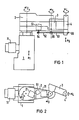
- the horizontal robot shown consists of a lifting part 1 with an electromotive drive 11, through which the swivel arm with the arm parts 2 and 3 can be displaced vertically in the direction of the double arrow a1.
- the arm part 2 of the swivel arm can be swiveled by an electric drive (not shown) with a gear around the axis of rotation at the angle ⁇ 2.
- a swivel joint is arranged, about which the second arm part 3 can be pivoted at the angle a.
- the combined pivot-lifting axis 4 at the end of the arm part 3 consists of a holder 41 in which a rotating part 43 serving as a pivot axis is rotatably mounted via bearings 42.
- the lifting part 48 is axially supported via ball bushings 44, which essentially consists of guide tubes 45 and an end plate 46.
- An electric motor 51 arranged vertically in the arm part 2 serves to drive the rotating part 43, the movement of which is transmitted via two toothed belts 52 and 53 and corresponding toothed belt rollers 54, 55 and 56 to the axis of rotation with the rotating part 43.
- a pneumatic rotary drive 61 arranged in the arm part 3 serves for the lifting movement.
Landscapes
- Engineering & Computer Science (AREA)
- Robotics (AREA)
- Mechanical Engineering (AREA)
- Manipulator (AREA)
Description
- Die Erfindung bezieht sich auf einen Industrieroboter mit Schwenkarm, bei dem zwei aufeinanderfolgende Armteile in zueinander parallelen Horizontalebenen schwenkbar sind und anschließend mindestens eine Dreh- und eine Hubachse vorgesehen sind.
- Mit diesem Oberbegriff wird im wesentlichen auf eine Anordnung Bezug genommen, wie sie beispielsweise aus der US-A-43 48 142 (Figur 1) bekannt ist.
- Häufig werden heute zum Antrieb in den einzelnen Roboterachsen elektrische Einzelantriebe benutzt (vgl. z. B. EP-A-102082 oder DE-B-11 48 721). Falls die Antriebe in die einzelnen Achsen integriert sind, bekommt man zwar sehr präzise Bewegungen, muß aber andererseits in Kauf nehmen, daß u. U. die Einheiten an der Roboterspitze relativ schwer und groß werden, so daß sich Schwierigkeiten bei diffizilen Arbeitsvorgängen hoher Geschwindigkeit ergeben können.
- Die Aufgabe der vorliegenden Erfindung besteht darin, die Dreh-Hubachse an der Roboterspitze, d. h. an der an den Schwenkarm anschlie- ßenden Stelle konstruktuv so zu gestalten, daß gedrungene Bauform mit relativ geringem Trägheitsmoment vereinbar sind.
- Diese Aufgabe wird durch den Roboter gemäß Anspruch 1 gelost.
- Zur Bewegung der Hubachse kann dabei ein Drehantrieb dienen, der über einen Hebel mit der Hubachse verbunden ist, während zur Bewegung der Drehachse ein Zahnriemengetriebe diennen kann, das mit einem im Schwenkarm angeordneten elektrischen Motor gekuppelt ist.
- Die kombinierte Hub-Drehachse kann dabei im wesentlichen konstruktiv zylindrisch gestaltet sein, wobei der äußere drehbare Teil durch das Zahnriemengetriebe angetrieben wird, während der innen längsverschieblich gelagerte Hubteil über den Hebel bewegt wird. Durch diese Konstruktion können zentrisch auch die elektrischen und pneumatischen Anschlußleitungen für einen nachfolgenden Greifer geführt sein.
- Anhand eines in der Zeichnung dargestellten Ausführungsbeispiels sei die Erfindung näher erläutert ; es zeigen :
- Figur 1 eine schematische Seitenansicht des Roboters,
- Figur 2 eine Draufsicht auf den Roboter und
- Figur 3 nähere Details der kombinierten Schwenk-Hubachse.
- Wie aus Figur 1 ersichtlich, besteht der dargestellte Horizontalroboter aus einem Hubteil 1 mit einem elektromotorischen Antrieb 11, durch das der Schwenkarm mit den Armteilen 2 und 3 vertikal in Richtung des Doppelpfeiles a1 verschiebbar ist. Der Armteil 2 des Schwenkarmes ist durch einen nicht dargestellten Elektroantrieb mit Getriebe um die Drehachse mit dem Winkel α2 schwenkbar. Am vorderen Ende dieses konisch zulaufenden Armteiles 2 ist ein Drehgelenk angeordnet, um das mit dem Winkel a der zweite Armteil 3 schwenkbar ist.
- Am vorderen Ende des Armteiles 3 findet sich dann noch eine weitere Einheit in Form einer kombinierten Schwenk-Hubachse 4 mit dem Drehwinkel a 4 und der Hubbewegung a5.
- Wie aus der Zeichnung ersichtlich, besteht die kombinierte Schwenk-Hubachse 4 am Ende des Armteiles 3 aus einer Halterung 41, in der über Lager 42 drehbar ein als Schwenkachse dienendes Drehteil 43 gelagert ist. In diesem Drehteil 43 ist über Kugelbüchsen 44 axial das Hubteil 48 gelagert, welches im wesentlichen aus Führungsrohren 45 und einer Endplattes 46 besteht.
- Zum Antrieb des Drehteils 43 dient ein im Armteil 2 vertikal angeordneter Elektromotor 51, dessen Bewegung über zwei Zahnriemen 52 und 53 und entsprechende Zahnriemenrollen 54, 55 und 56 auf die Drehachse mit dem Drehteil 43 übertragen wird.
- Zur Hubbewegung dient ein im Armteil 3 angeordneter pneumatischer Drehantrieb 61, dessen Drehbewegung über einen gelenkig gelagerten Hebel 62, der in einem im Hubteil 48 angeordneten Auge 47 mündet, in eine entsprechende Hubbewegung a5 des Hubteiles 48 umgesetzt wird.
Claims (1)
- Industrieroboter mit Schwenkarm, bei dem zwei aufeinanderfolgende Armteile (2, 3) in zueinander parallelen Horizontalebenen schwenkbar sind und anschließend mindestens eine kombinierte Dreh- und Hubachse (4) vorgesehen ist, wobei die Bewegung in der Drehachse (4) und die Bewegung der in der Drehachse längsverschieblich gelagerten Hubachse (a5) von im Schwenkarm (2, 3) angeordneten Antrieben (51, 61) abgeleitet sind, gekennzeichnet durch eine zylindrische Drehachse mit Außenantrieb durch Zahnriemen (53) und durch eine Hubachse (a5), die über einen gelenkig gelagerten Hebel (62) von einem pneumatischen Drehantrieb (61) bewegbar ist.
Applications Claiming Priority (3)
| Application Number | Priority Date | Filing Date | Title |
|---|---|---|---|
| DE19853513638 DE3513638A1 (de) | 1985-04-16 | 1985-04-16 | Industrieroboter mit schwenkarm |
| DE8511182U DE8511182U1 (de) | 1985-04-16 | 1985-04-16 | |
| DE3513638 | 1985-04-16 |
Publications (2)
| Publication Number | Publication Date |
|---|---|
| EP0199146A1 EP0199146A1 (de) | 1986-10-29 |
| EP0199146B1 true EP0199146B1 (de) | 1989-10-11 |
Family
ID=25831396
Family Applications (1)
| Application Number | Title | Priority Date | Filing Date |
|---|---|---|---|
| EP86104431A Expired EP0199146B1 (de) | 1985-04-16 | 1986-04-01 | Industrieroboter mit Schwenkarm |
Country Status (4)
| Country | Link |
|---|---|
| US (1) | US4725192A (de) |
| EP (1) | EP0199146B1 (de) |
| JP (1) | JPS61241081A (de) |
| DE (2) | DE3513638A1 (de) |
Cited By (1)
| Publication number | Priority date | Publication date | Assignee | Title |
|---|---|---|---|---|
| CN106217362A (zh) * | 2016-08-30 | 2016-12-14 | 四川大友机器人有限公司 | 重型码垛传送机器人 |
Families Citing this family (4)
| Publication number | Priority date | Publication date | Assignee | Title |
|---|---|---|---|---|
| DE3876241D1 (de) * | 1987-03-31 | 1993-01-07 | Siemens Ag | Industrieroboter. |
| US4787813A (en) * | 1987-08-26 | 1988-11-29 | Watkins-Johnson Company | Industrial robot for use in clean room environment |
| CN106002968B (zh) * | 2016-06-12 | 2018-11-30 | 上海咏姿时装有限公司 | 一种文胸夹持装置 |
| RU2751160C1 (ru) * | 2020-06-11 | 2021-07-08 | Общество с ограниченной ответственностью "РОБОТЕХ" | Промышленный манипулятор |
Family Cites Families (9)
| Publication number | Priority date | Publication date | Assignee | Title |
|---|---|---|---|---|
| BE582789A (de) * | 1958-09-19 | |||
| US3240358A (en) * | 1963-09-23 | 1966-03-15 | United Shoe Machinery Corp | Work piece feeders |
| US4036374A (en) * | 1975-11-04 | 1977-07-19 | Amc Industries, Inc. | Multi-motion parts handler |
| FR2451807A1 (fr) * | 1979-03-22 | 1980-10-17 | Renault | Manipulateur six axes |
| JPS58146690U (ja) * | 1982-03-25 | 1983-10-03 | 株式会社三協精機製作所 | 工業用ロボツトのヘツド |
| FR2527967B1 (fr) * | 1982-06-07 | 1985-07-19 | Merlin Gerin | Robot industriel perfectionne pilote par un automate programmable |
| DE3371609D1 (en) * | 1982-08-30 | 1987-06-25 | Hitachi Ltd | Industrial robot |
| JPS5969283A (ja) * | 1982-10-12 | 1984-04-19 | 豊田工機株式会社 | 水平多関節型ロボツト |
| CA1252135A (en) * | 1984-07-27 | 1989-04-04 | Richard S. Antoszewski | Pneumatic robot wrist |
-
1985
- 1985-04-16 DE DE19853513638 patent/DE3513638A1/de not_active Withdrawn
- 1985-04-16 DE DE8511182U patent/DE8511182U1/de not_active Expired
-
1986
- 1986-04-01 EP EP86104431A patent/EP0199146B1/de not_active Expired
- 1986-04-14 JP JP61085839A patent/JPS61241081A/ja active Pending
- 1986-04-15 US US06/852,333 patent/US4725192A/en not_active Expired - Fee Related
Cited By (1)
| Publication number | Priority date | Publication date | Assignee | Title |
|---|---|---|---|---|
| CN106217362A (zh) * | 2016-08-30 | 2016-12-14 | 四川大友机器人有限公司 | 重型码垛传送机器人 |
Also Published As
| Publication number | Publication date |
|---|---|
| JPS61241081A (ja) | 1986-10-27 |
| US4725192A (en) | 1988-02-16 |
| EP0199146A1 (de) | 1986-10-29 |
| DE8511182U1 (de) | 1988-05-11 |
| DE3513638A1 (de) | 1986-10-16 |
Similar Documents
| Publication | Publication Date | Title |
|---|---|---|
| DE3038419C2 (de) | Industrieroboter | |
| EP0000877B1 (de) | Manipulator zum Positionieren von Werkstücken oder anderen Lasten | |
| EP0178620B1 (de) | Robotergelenkanordnung | |
| DE4230352C2 (de) | Fingermodul einer Roboterhand | |
| DE2619336A1 (de) | Roboter- oder manipulatorkopf mit mindestens zwei senkrecht zueinander stehenden rotationsachsen | |
| EP0198315B1 (de) | Industrieroboter mit Schwenkarm | |
| DE60105373T2 (de) | Bearbeitungskopf für automatische Werkzeugmaschinen mit einer wechselbaren, nach aussen ragenden Futtereinheit | |
| EP1415758A1 (de) | Bearbeitungseinheit für eine programmgesteuerte Fräs- und Bohrmaschine | |
| EP0674122A2 (de) | Getriebemotor | |
| EP0014768B1 (de) | Vorrichtung zum Handhaben eines an einem Ausleger schwenk- und drehbar angeordneten Werkzeuges | |
| EP0199146B1 (de) | Industrieroboter mit Schwenkarm | |
| DE2742103C3 (de) | Zuführeinrichtung, insbesondere zum Bestücken, Entladen und Transportieren von Werkstücken | |
| CH624337A5 (en) | Manipulator | |
| DE3050664C2 (de) | Verfahren zur Bewegung eines Punktes in eine Lage,deren Koordinaten in einem orthogonalen System vorgegeben sind und Vorrichtung zur Druchf}hrung dieses Verfahrens | |
| WO2003086715A1 (de) | Roboterarm mit integrierter antriebseinrichtung | |
| DE2433954A1 (de) | Industrie-roboter | |
| DE3809751A1 (de) | Futterkopf fuer automatische werkzeugmaschinen | |
| DE3532265A1 (de) | Gelenkkopf fuer einen industrieroboter | |
| DE3410601A1 (de) | Greifer fuer industrieroboter | |
| DE4447162B4 (de) | Vorrichtung zur Bearbeitung von Oberflächen | |
| EP0334953B1 (de) | Fräs- und bohrkopf mit mehreren steuerbaren achsen | |
| DE202019101259U1 (de) | Schnellroboterarm | |
| DE2048407C3 (de) | Schleifmaschine zum Bearbeiten von bezüglich ihrer Mantellinien geraden Innenflächen von Hohlkörpern | |
| AT401705B (de) | Landmaschine, insbesondere kreiselheuwerbungsmaschine | |
| EP0218075A1 (de) | Gelenkroboter |
Legal Events
| Date | Code | Title | Description |
|---|---|---|---|
| PUAI | Public reference made under article 153(3) epc to a published international application that has entered the european phase |
Free format text: ORIGINAL CODE: 0009012 |
|
| AK | Designated contracting states |
Kind code of ref document: A1 Designated state(s): DE FR IT SE |
|
| 17P | Request for examination filed |
Effective date: 19861127 |
|
| 17Q | First examination report despatched |
Effective date: 19880613 |
|
| RAP1 | Party data changed (applicant data changed or rights of an application transferred) |
Owner name: SIEMENS AKTIENGESELLSCHAFT BERLIN UND MUENCHEN |
|
| GRAA | (expected) grant |
Free format text: ORIGINAL CODE: 0009210 |
|
| AK | Designated contracting states |
Kind code of ref document: B1 Designated state(s): DE FR IT SE |
|
| REF | Corresponds to: |
Ref document number: 3666172 Country of ref document: DE Date of ref document: 19891116 |
|
| ET | Fr: translation filed | ||
| ITF | It: translation for a ep patent filed |
Owner name: STUDIO JAUMANN |
|
| PGFP | Annual fee paid to national office [announced via postgrant information from national office to epo] |
Ref country code: DE Payment date: 19900625 Year of fee payment: 5 |
|
| PLBE | No opposition filed within time limit |
Free format text: ORIGINAL CODE: 0009261 |
|
| STAA | Information on the status of an ep patent application or granted ep patent |
Free format text: STATUS: NO OPPOSITION FILED WITHIN TIME LIMIT |
|
| 26N | No opposition filed | ||
| PGFP | Annual fee paid to national office [announced via postgrant information from national office to epo] |
Ref country code: SE Payment date: 19910423 Year of fee payment: 6 Ref country code: FR Payment date: 19910423 Year of fee payment: 6 |
|
| ITTA | It: last paid annual fee | ||
| PG25 | Lapsed in a contracting state [announced via postgrant information from national office to epo] |
Ref country code: DE Effective date: 19920201 |
|
| PG25 | Lapsed in a contracting state [announced via postgrant information from national office to epo] |
Ref country code: SE Effective date: 19920402 |
|
| PG25 | Lapsed in a contracting state [announced via postgrant information from national office to epo] |
Ref country code: FR Effective date: 19921230 |
|
| REG | Reference to a national code |
Ref country code: FR Ref legal event code: ST |
|
| EUG | Se: european patent has lapsed |
Ref document number: 86104431.1 Effective date: 19921108 |
|
| PG25 | Lapsed in a contracting state [announced via postgrant information from national office to epo] |
Ref country code: IT Free format text: LAPSE BECAUSE OF NON-PAYMENT OF DUE FEES;WARNING: LAPSES OF ITALIAN PATENTS WITH EFFECTIVE DATE BEFORE 2007 MAY HAVE OCCURRED AT ANY TIME BEFORE 2007. THE CORRECT EFFECTIVE DATE MAY BE DIFFERENT FROM THE ONE RECORDED. Effective date: 20050401 |