EP0199115B1 - Verfahren und Vorrichtung zur individuellen Anpassung eines Lattenrostes - Google Patents
Verfahren und Vorrichtung zur individuellen Anpassung eines Lattenrostes Download PDFInfo
- Publication number
- EP0199115B1 EP0199115B1 EP86103977A EP86103977A EP0199115B1 EP 0199115 B1 EP0199115 B1 EP 0199115B1 EP 86103977 A EP86103977 A EP 86103977A EP 86103977 A EP86103977 A EP 86103977A EP 0199115 B1 EP0199115 B1 EP 0199115B1
- Authority
- EP
- European Patent Office
- Prior art keywords
- frame
- individual
- base
- sub
- slatted
- Prior art date
- Legal status (The legal status is an assumption and is not a legal conclusion. Google has not performed a legal analysis and makes no representation as to the accuracy of the status listed.)
- Expired
Links
Images

Classifications
-
- A—HUMAN NECESSITIES
- A47—FURNITURE; DOMESTIC ARTICLES OR APPLIANCES; COFFEE MILLS; SPICE MILLS; SUCTION CLEANERS IN GENERAL
- A47C—CHAIRS; SOFAS; BEDS
- A47C31/00—Details or accessories for chairs, beds, or the like, not provided for in other groups of this subclass, e.g. upholstery fasteners, mattress protectors, stretching devices for mattress nets
- A47C31/12—Means, e.g. measuring means, for adapting chairs, beds or mattresses to the shape or weight of persons
- A47C31/123—Means, e.g. measuring means, for adapting chairs, beds or mattresses to the shape or weight of persons for beds or mattresses
-
- A—HUMAN NECESSITIES
- A47—FURNITURE; DOMESTIC ARTICLES OR APPLIANCES; COFFEE MILLS; SPICE MILLS; SUCTION CLEANERS IN GENERAL
- A47C—CHAIRS; SOFAS; BEDS
- A47C23/00—Spring mattresses with rigid frame or forming part of the bedstead, e.g. box springs; Divan bases; Slatted bed bases
- A47C23/06—Spring mattresses with rigid frame or forming part of the bedstead, e.g. box springs; Divan bases; Slatted bed bases using wooden springs, e.g. of slat type
Definitions
- the invention relates to a method for individually adapting a slatted frame to the anatomy and the weight of the person to be picked up.
- Such slatted frames are increasingly being used as spring support elements of mattresses to ensure optimal support and suspension, while at the same time individual adjustment of the individual slats of the slatted frame to the weight acting on the person lying on it is possible.
- the present invention is therefore based on the object of providing a method and a device for individually adapting such a slatted frame which does not require separate measuring elements and with which adaptation is also possible when the person in question is standing.
- the slatted frame to be adjusted and pivoted is placed vertically, adapted to the size of the person by vertical displacement in its height bearing and then the individual slats of the slatted frame in height and / or spring stiffness can be adjusted to the person's anatomy, in particular the curvature of the spine.
- a device for performing this method according to the invention consists in that the slatted frame is mounted on a subframe to which a sliding mechanism is articulated laterally, the lower stationary part of which is pivotally mounted in a base frame.
- the sliding mechanism can each have a gas spring arranged on both sides of the subframe, the upper ends of the gas spring cylinder are attached laterally to the subframe and the lower ends of the gas spring piston are supported on sliding guides for the subframe which are pivotably held on the base frame.
- the slide guides expediently consist of approximately U-shaped frames into which rails connected to the underframe via retaining webs slide.
- the upper ends of two further gas springs can also be articulated on the slide guides above their pivot point in the base frame, the other ends of which are articulated on the lower edge of the base frame in such a way that the gas springs in the erected state of the slatted frame are at an angle of approximately 45 ° .
- the slatted frames can thus be adjusted to the person standing, whereby, if necessary, the determined values can be checked after the slatted frame has been moved into the horizontal position.
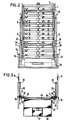
- the illustrated embodiment shows a slatted frame 1 in a vertical position.
- a subframe 2 On the underside of the slatted frame 1, a subframe 2 is attached, on each side of which - as can be seen in particular from FIGS. 2 and 3 - a gas spring 4 and 5 is attached via a corresponding holder 6 and 7 to the upper end of the gas spring cylinder.
- the gas spring pistons 8 and 9 are supported with their lower ends on the so-called slide guide 10 and 11, which are each pivotally supported by bolts 12 and 13 in the side spaces 14 and 15 of a base frame 16.
- the slide guides themselves consist of approximately U-shaped frames 17 and 18, in which rails 19 and 20 slide, which are connected to the subframe 2 via narrow webs 21 and 22.
- the slatted frame 1 can be moved vertically upwards or downwards in a simple manner by means of the handles 23 on the subframe 2 and then held in the desired height by means of locking pins 24 and 25 which are held in a correspondingly springy manner.
- two further gas springs 27 and 28 are provided on both sides, the upper end of which is pivotally attached above the pivot points 12 and 13 to the slide guides 10 and 11 , while the lower ends of the gas springs are fixed by corresponding bolts 29 and 30 on the lower bars 31 and 32 of the base frame 16.
- these gas springs 27 and 28 are inclined at approximately an angle of 45 ° to the horizontal and thus allow the slatted frame 1 to be lowered slightly into the horizontal position, as is indicated by dash-dotted lines.
- a mobile platform 40 is then set up in front of the vertically positioned slatted frame 1, into which, for example, a personal scale 41 can be integrated.
- the person to whom the slatted frame is to be adjusted then stands on the top step 42 of the platform 40 with its back against the slatted frame 1, whereupon this slatted frame is then adjusted to the appropriate height by means of the gas springs 4 and 5, which is optimal Lying position corresponds to the person.
- the individual slats 45 of the slatted frame 1 can be adjusted to the required height and spring hardness, for example in the area of the shoulder position and the hip position and the spinal area in between.
- the values determined in this way can then be transferred in a simple manner via the slatted frame to be delivered to the customer, and the latter can be adjusted accordingly.
- the slatted frame can then also be folded over, in order to check the adjustment results on the person lying on the slatted frame if necessary.
Landscapes
- Accommodation For Nursing Or Treatment Tables (AREA)
- Auxiliary Devices For And Details Of Packaging Control (AREA)
- Shaping Of Tube Ends By Bending Or Straightening (AREA)
- Housing For Livestock And Birds (AREA)
- Orthopedics, Nursing, And Contraception (AREA)
Description
- Die Erfindung betrifft ein Verfahren zur individuellen Anpassung eines Lattenrostes an die Anatomie und das Gewicht der aufzunehmenden Person.
- Derartige Lattenroste werden in zunehmendem Maße als Unterfederungselemente von Matratzen verwendet, um eine optimale Abstützung und Federung zu gewährleisten, wobei gleichzeitig eine individuelle Anpassung der einzelnen Leisten des Lattenrostes auf das von der aufliegenden Person einwirkende Gewicht möglich ist.
- Es hat sich dabei als zweckmäßig erwiesen, einen derartigen Lattenrost schon beim Kauf desselben an die individuellen Maße und Bedürfnisse der später darauf liegenden Person anzupassen. Dies ist besonders wichtig, weil eine Matratze mit der zugehörigen Unterfederung alle abzustützenden Körperpartien gleichmäßig abstützen soll, wobei insbesondere eine individuelle Anpassung an die jeweilige Krümmung der Wirbelsäule wünschenswert ist.
- Es sind in diesem Zusammenhang schon verschiedene Systeme für eine derartige individuelle Anpassung bekannt geworden, wie beispielsweise aus der DE-AS 25 42 268 oder dem DE-GM 74 00 562. Bei diesen Geräten wird die Anpassung der Federung an den jeweiligen Auflagedruck einzelner Körperstellen der darauf liegenden Person durch Meßglieder erreicht, die jeder einzelnen Latte zugeordnet sind und dabei das an diesen Meßstellen aufruhende Gewicht ermitteln. Aus diesen Werten können dann die einzelnen Latten des Lattenrostes individuell härter oder weicher eingestellt werden.
- Diese bekannten Vorrichtungen haben jedoch den Nachteil, daß sie sehr aufwendig und damit störanfällig sind, und daß mit ihnen die Personen, an denen der Lattenrost angepaßt werden soll, nur im Liegen vermessen werden können, wozu in öffentlichen Geschäften jedoch oftmals eine erhebliche Hemmschwelle zu überwinden ist.
- Der vorliegenden Erfindung liegt daher die Aufgabe zugrunde, ein Verfahren und eine Vorrichtung zur individuellen Anpassung eines derartigen Lattenrostes zu schaffen, der ohne gesonderte Meßglieder auskommt und mit dem eine Anpassung auch in stehender Haltung der jeweiligen Person möglich ist.
- Zur Lösung dieser Aufgabe ist erfindungsgemäß vorgesehen, daß unmittelbar hinter der auf einem Podest stehenden Person der anzupassende und schwenkbar gehalterte Lattenrost senkrecht aufgestellt, durch senkrechte Verschiebung in seinem Höhenlager der Größe der Person angepaßt und anschließend die einzelnen Latten des Lattenrostes in Höhenlage und/oder Federsteifigkeit auf die Anatomie, insbesondere die Wirbelsäulenkrümmung, der Person eingestellt werden.
- Eine Vorrichtung zur Durchführung dieses Verfahrens besteht erfindungsgemäß darin, daß der Lattenrost auf einem Unterrahmen montiert ist, an den seitlich ein Verschiebemechanismus angelenkt ist, dessen unterer stationärer Teil schwenkbar in einem Grundgestell gehaltert ist.
- Dabei kann der Verschiebemechanismus je eine beiderseits des Unterrahmens angeordnete Gasfeder aufweisen, deren obere Enden der Gasfederzylinder seitlich am Unterrahmen befestigt sind und deren untere Enden der Gasfederkolben sich auf am Grundgestell schwenkbar gehalterten Gleitführungen für den Unterrahmen abstützen.
- Dabei bestehen die Gleitführungen zweckmäßigerweise aus angenähert U-förmigen Rahmen, in die mit dem Untergestell über Haltestege verbundene Schienen gleiten.
- Zur Abfederung der Schwenkbewegung des Lattenrostes können darüberhinaus an den Gleitführungen oberhalb ihrer Drehpunkt im Grundrahmen die oberen Enden zweier weiterer Gasfedern angelenkt sein, deren andere Enden an der Unterkante des Grundrahmens derart angelenkt sind, daß die Gasfedern im aufgestellten Zustand des Lattenrostes etwa unter einem Winkel von 45° verlaufen.
- Mit einem derartigen Verfahren und einer entsprechend ausgebildeten Vorrichtung können somit die Lattenroste im Stehen an die jeweilige Person angepaßt werden, wobei ggf. nach Umlegen des Lattenrostes in die horizontale Lage eine Nachprüfung der ermittelten Werte möglich ist.
- Anhand einer schematischen Zeichnung sind Aufbau und Wirkungsweise einer Vorrichtung nach der Erfindung näher erläutert. Dabei zeigen
- Fig. 1 eine Seitenansicht der Vorrichtung
- Fig. 2 eine Ansicht von vorn auf die Vorrichtung und
- Fig. 3 einen Querschnitt durch die Vorrichtung in Höhe der Schnittlinie 111-111 nach Fig. 1
- Das dargestellte Ausführungsbeispiel zeigt einen Lattenrost 1 in senkrechter Stellung. Auf der Unterseite des Lattenrostes 1 ist ein Unterrahmen 2 befestigt, an dem auf jeder Seite - wie man insbesondere aus Fig. 2 und 3 ersieht - je eine Gasfeder 4 und 5 über eine entsprechende Halterung 6 und 7 am oberen Ende des Gasfederzylinders befestigt. Die Gasfederkolben 8 und 9 stützen sich dabei mit ihren unteren Enden auf der sogenannten Gleitführung 10 bzw. 11 ab, die jeweils über Bolzen 12 und 13 in den Seitenräumen 14 und 15 eines Grundrahmens 16 schwenkbar gehaltert sind.
- Die Gleitführungen selbst bestehen aus angenähert U-förmigen Rahmen 17 und 18, in denen Schienen 19 und 20 gleiten, die über schmale Stege 21 und 22 mit dem Unterrahmen 2 in Verbindung stehen.
- Damit kann auf einfache Weise über die Handgriffe 23 am Unterrahmen 2 der Lattenrost 1 senkrecht nach oben oder unten verfahren und dann über entsprechend federnd gehaltene Arretierungsstifte 24 und 25 in der gewünschten Höhenlage festgehalten werden.
- Zur Abstützung der Schwenkbewegung des Lattenrostes 1, der sich in senkrechter Stellung gegen einen Anschlag 26 am Grundrahmen 16 abstützt, sind beidseitig zwei weitere Gasfedern 27 und 28 vorgesehen, deren oberes Ende oberhalb der Drehpunkte 12 und 13 an den Gleitführungen 10 und 11 schwenkbar befestigt sind, während die unteren Enden der Gasfedern über entsprechende Bolzen 29 und 30 an den Unterholmen 31 und 32 des Grundgestells 16 festgelegt sind. In senkrechter Stellung des Lattenrostes liegen diese Gasfedern 27 und 28 etwa unter einem Winkel von 45° zur Horizontalen geneigt und ermöglichen somit ein leichtes Absenken des Lattenrostes 1 in die horizontale Lage, wie sie strichpunktiert angedeutet ist.
- Vor dem senkrecht aufgestellten Lattenrost 1 wird dann noch ein fahrbares Podest 40 aufgestellt, in das beispielsweise eine Personenwaaage 41 integriert sein kann. Die Person, an die der Lattenrost angepaßt werden soll, stellt sich dann auf die oberste Stufe 42 des Podestes 40 mit dem Rücken gegen den Lattenrost 1, woraufhin dann dieser Lattenrost mittels der Gasfedern 4 und 5 auf die entsprechende Höhe einjustiert wird, die einer optimalen Liegestellung der Person entspricht. Anschließend können - wie insbesondere aus der Vorderansicht nach Fig. 2 zu ersehen ist - die einzelnen Latten 45 des Lattenrostes 1 beispielsweise im Bereich der Schulterposition sowie der Hüftposition und des dazwischenliegenden Wirbelsäulenbereichs auf die erforderliche Höhe und Federhärte eingestellt werden. Die so ermittelten Werte können dann auf einfache Weise über den an den Kunden auszuliefernden Lattenrost übertragen und dieser entsprechend eingestellt werden.
- Nach der entsprechenden Einstellung in der senkrechten Lage des Lattenrostes kann dieser dann auch noch umgelegt werden, um ggf. die Einstellergebnisse an der dann auf dem Lattenrost liegenden Person noch einmal zu überprüfen.
- Mit der beschriebenen Vorrichtung ist es also auf sehr einfache Weise möglich, die einzelnen Latten genau an die entsprechende Anatomie des Käufers anzupassen, ohne daß sich die Person dazu auf den Lattenrost legen muß.
Claims (6)
Priority Applications (1)
| Application Number | Priority Date | Filing Date | Title |
|---|---|---|---|
| AT86103977T ATE44216T1 (de) | 1985-03-26 | 1986-03-22 | Verfahren und vorrichtung zur individuellen anpassung eines lattenrostes. |
Applications Claiming Priority (2)
| Application Number | Priority Date | Filing Date | Title |
|---|---|---|---|
| DE3510972 | 1985-03-26 | ||
| DE3510972A DE3510972C1 (de) | 1985-03-26 | 1985-03-26 | Verfahren und Vorrichtung zur individuellen Anpassung eines Lattenrostes |
Publications (3)
| Publication Number | Publication Date |
|---|---|
| EP0199115A2 EP0199115A2 (de) | 1986-10-29 |
| EP0199115A3 EP0199115A3 (en) | 1987-05-27 |
| EP0199115B1 true EP0199115B1 (de) | 1989-06-28 |
Family
ID=6266391
Family Applications (1)
| Application Number | Title | Priority Date | Filing Date |
|---|---|---|---|
| EP86103977A Expired EP0199115B1 (de) | 1985-03-26 | 1986-03-22 | Verfahren und Vorrichtung zur individuellen Anpassung eines Lattenrostes |
Country Status (3)
| Country | Link |
|---|---|
| EP (1) | EP0199115B1 (de) |
| AT (1) | ATE44216T1 (de) |
| DE (2) | DE3510972C1 (de) |
Families Citing this family (2)
| Publication number | Priority date | Publication date | Assignee | Title |
|---|---|---|---|---|
| FR2738129B1 (fr) * | 1995-09-06 | 1997-10-24 | Turquin Jean Luc | Sommier a lattes sans cadre, autocompense et procede de realisation de tels sommiers |
| DE19851561A1 (de) * | 1998-11-09 | 2000-05-11 | Guenter Kreisner | Meßvorrichtung zur Feststellung des Federungszustandes von Bettfederungen |
Family Cites Families (4)
| Publication number | Priority date | Publication date | Assignee | Title |
|---|---|---|---|---|
| US2887691A (en) * | 1957-06-26 | 1959-05-26 | Lawrence J Talarico | Hospital bed |
| CH585541A5 (de) * | 1974-09-25 | 1977-03-15 | Marpal Ag | |
| GB2077580B (en) * | 1980-06-02 | 1984-10-31 | Blakeway Richard Stanley Olds | Body support |
| DE3106882A1 (de) * | 1981-02-24 | 1982-12-09 | Nikolai 8000 München Regehr | Anpassbarer stuhl, zur schablonenherstellung |
-
1985
- 1985-03-26 DE DE3510972A patent/DE3510972C1/de not_active Expired
-
1986
- 1986-03-22 AT AT86103977T patent/ATE44216T1/de not_active IP Right Cessation
- 1986-03-22 EP EP86103977A patent/EP0199115B1/de not_active Expired
- 1986-03-22 DE DE8686103977T patent/DE3664099D1/de not_active Expired
Also Published As
| Publication number | Publication date |
|---|---|
| DE3510972C1 (de) | 1986-12-11 |
| EP0199115A2 (de) | 1986-10-29 |
| DE3664099D1 (en) | 1989-08-03 |
| ATE44216T1 (de) | 1989-07-15 |
| EP0199115A3 (en) | 1987-05-27 |
Similar Documents
| Publication | Publication Date | Title |
|---|---|---|
| EP0199115B1 (de) | Verfahren und Vorrichtung zur individuellen Anpassung eines Lattenrostes | |
| DE202008005094U1 (de) | Stehgerät zur Rehabilitation körperbeeinträchtigter Personen | |
| DE29623535U1 (de) | Hubvorrichtung für Sitz- oder Liegeflächen | |
| DE6603647U (de) | Roentgentischausruestung | |
| EP0035199A2 (de) | Eckpolstermöbel mit Eckablagefläche | |
| DE3636898C1 (en) | Stand with at least one adjustable standing area for a visual display unit | |
| EP0923331B1 (de) | Lattenrost | |
| DE102018002483A1 (de) | Kombinationsmöbel sowie Sitzmöbel | |
| DE3127614A1 (de) | Zahnaerztliche einrichtung | |
| DE2650759B2 (de) | Höhenverstellbares Liegemöbel, insbesondere Krankenbett | |
| DE726639C (de) | Ruhebett mit Wenderahmen | |
| DE2503078A1 (de) | Vorrichtung zum hoehenverstellen einer platte o.dgl. | |
| DE3418072A1 (de) | Vorrichtung zum vertikalen verstellen von betteilen und dgl. | |
| DE1793900U (de) | Hocker od. dgl. | |
| DE3538595A1 (de) | Sitz fuer oeffentliche verkehrsmittel | |
| DE3227062A1 (de) | Lese-hilfe-geraet | |
| DE1733879U (de) | Hoehenverstellbarer tisch. | |
| DE2801726C2 (de) | Matratzenauflage mit einem starren Unterrahmen | |
| DE200845C (de) | ||
| DE2732277A1 (de) | Vorrichtung zur praesentation von liegeelementen | |
| DE102020131156A1 (de) | Elektromotorisch verstellbare Stützeinrichtung | |
| DE8709847U1 (de) | Modulartiges Versorgungselement | |
| AT237831B (de) | Sitzbank | |
| DE7930794U1 (de) | Untersuchungsdiwan | |
| DE2356406A1 (de) | Bettcouch |
Legal Events
| Date | Code | Title | Description |
|---|---|---|---|
| PUAI | Public reference made under article 153(3) epc to a published international application that has entered the european phase |
Free format text: ORIGINAL CODE: 0009012 |
|
| 17P | Request for examination filed |
Effective date: 19860322 |
|
| AK | Designated contracting states |
Kind code of ref document: A2 Designated state(s): AT BE CH DE FR GB LI NL SE |
|
| PUAL | Search report despatched |
Free format text: ORIGINAL CODE: 0009013 |
|
| AK | Designated contracting states |
Kind code of ref document: A3 Designated state(s): AT BE CH DE FR GB LI NL SE |
|
| 17Q | First examination report despatched |
Effective date: 19880707 |
|
| GRAA | (expected) grant |
Free format text: ORIGINAL CODE: 0009210 |
|
| AK | Designated contracting states |
Kind code of ref document: B1 Designated state(s): AT BE CH DE FR GB LI NL SE |
|
| PG25 | Lapsed in a contracting state [announced via postgrant information from national office to epo] |
Ref country code: SE Effective date: 19890628 Ref country code: NL Effective date: 19890628 Ref country code: GB Effective date: 19890628 Ref country code: FR Free format text: THE PATENT HAS BEEN ANNULLED BY A DECISION OF A NATIONAL AUTHORITY Effective date: 19890628 Ref country code: BE Effective date: 19890628 |
|
| REF | Corresponds to: |
Ref document number: 44216 Country of ref document: AT Date of ref document: 19890715 Kind code of ref document: T |
|
| REF | Corresponds to: |
Ref document number: 3664099 Country of ref document: DE Date of ref document: 19890803 |
|
| EN | Fr: translation not filed | ||
| NLV1 | Nl: lapsed or annulled due to failure to fulfill the requirements of art. 29p and 29m of the patents act | ||
| GBV | Gb: ep patent (uk) treated as always having been void in accordance with gb section 77(7)/1977 [no translation filed] | ||
| PG25 | Lapsed in a contracting state [announced via postgrant information from national office to epo] |
Ref country code: LI Effective date: 19900331 Ref country code: CH Effective date: 19900331 |
|
| PLBE | No opposition filed within time limit |
Free format text: ORIGINAL CODE: 0009261 |
|
| STAA | Information on the status of an ep patent application or granted ep patent |
Free format text: STATUS: NO OPPOSITION FILED WITHIN TIME LIMIT |
|
| 26N | No opposition filed | ||
| REG | Reference to a national code |
Ref country code: CH Ref legal event code: PL |
|
| PGFP | Annual fee paid to national office [announced via postgrant information from national office to epo] |
Ref country code: AT Payment date: 19920212 Year of fee payment: 7 |
|
| PGFP | Annual fee paid to national office [announced via postgrant information from national office to epo] |
Ref country code: DE Payment date: 19920331 Year of fee payment: 7 |
|
| PG25 | Lapsed in a contracting state [announced via postgrant information from national office to epo] |
Ref country code: AT Effective date: 19930322 |
|
| PG25 | Lapsed in a contracting state [announced via postgrant information from national office to epo] |
Ref country code: DE Effective date: 19931201 |
|
| P01 | Opt-out of the competence of the unified patent court (upc) registered |
Effective date: 20230522 |