EP0198933A2 - Pivot avec blocage de charge, en particulier pour microscopes d'opération et suspension pour ces derniers - Google Patents
Pivot avec blocage de charge, en particulier pour microscopes d'opération et suspension pour ces derniers Download PDFInfo
- Publication number
- EP0198933A2 EP0198933A2 EP85104918A EP85104918A EP0198933A2 EP 0198933 A2 EP0198933 A2 EP 0198933A2 EP 85104918 A EP85104918 A EP 85104918A EP 85104918 A EP85104918 A EP 85104918A EP 0198933 A2 EP0198933 A2 EP 0198933A2
- Authority
- EP
- European Patent Office
- Prior art keywords
- joint
- joint ball
- locking
- self
- clamping elements
- Prior art date
- Legal status (The legal status is an assumption and is not a legal conclusion. Google has not performed a legal analysis and makes no representation as to the accuracy of the status listed.)
- Granted
Links
Images

Classifications
-
- G—PHYSICS
- G02—OPTICS
- G02B—OPTICAL ELEMENTS, SYSTEMS OR APPARATUS
- G02B21/00—Microscopes
- G02B21/24—Base structure
-
- A—HUMAN NECESSITIES
- A61—MEDICAL OR VETERINARY SCIENCE; HYGIENE
- A61B—DIAGNOSIS; SURGERY; IDENTIFICATION
- A61B90/00—Instruments, implements or accessories specially adapted for surgery or diagnosis and not covered by any of the groups A61B1/00 - A61B50/00, e.g. for luxation treatment or for protecting wound edges
- A61B90/50—Supports for surgical instruments, e.g. articulated arms
-
- B—PERFORMING OPERATIONS; TRANSPORTING
- B23—MACHINE TOOLS; METAL-WORKING NOT OTHERWISE PROVIDED FOR
- B23Q—DETAILS, COMPONENTS, OR ACCESSORIES FOR MACHINE TOOLS, e.g. ARRANGEMENTS FOR COPYING OR CONTROLLING; MACHINE TOOLS IN GENERAL CHARACTERISED BY THE CONSTRUCTION OF PARTICULAR DETAILS OR COMPONENTS; COMBINATIONS OR ASSOCIATIONS OF METAL-WORKING MACHINES, NOT DIRECTED TO A PARTICULAR RESULT
- B23Q1/00—Members which are comprised in the general build-up of a form of machine, particularly relatively large fixed members
- B23Q1/25—Movable or adjustable work or tool supports
- B23Q1/26—Movable or adjustable work or tool supports characterised by constructional features relating to the co-operation of relatively movable members; Means for preventing relative movement of such members
- B23Q1/28—Means for securing sliding members in any desired position
-
- B—PERFORMING OPERATIONS; TRANSPORTING
- B23—MACHINE TOOLS; METAL-WORKING NOT OTHERWISE PROVIDED FOR
- B23Q—DETAILS, COMPONENTS, OR ACCESSORIES FOR MACHINE TOOLS, e.g. ARRANGEMENTS FOR COPYING OR CONTROLLING; MACHINE TOOLS IN GENERAL CHARACTERISED BY THE CONSTRUCTION OF PARTICULAR DETAILS OR COMPONENTS; COMBINATIONS OR ASSOCIATIONS OF METAL-WORKING MACHINES, NOT DIRECTED TO A PARTICULAR RESULT
- B23Q1/00—Members which are comprised in the general build-up of a form of machine, particularly relatively large fixed members
- B23Q1/25—Movable or adjustable work or tool supports
- B23Q1/44—Movable or adjustable work or tool supports using particular mechanisms
- B23Q1/50—Movable or adjustable work or tool supports using particular mechanisms with rotating pairs only, the rotating pairs being the first two elements of the mechanism
- B23Q1/54—Movable or adjustable work or tool supports using particular mechanisms with rotating pairs only, the rotating pairs being the first two elements of the mechanism two rotating pairs only
- B23Q1/545—Movable or adjustable work or tool supports using particular mechanisms with rotating pairs only, the rotating pairs being the first two elements of the mechanism two rotating pairs only comprising spherical surfaces
-
- F—MECHANICAL ENGINEERING; LIGHTING; HEATING; WEAPONS; BLASTING
- F16—ENGINEERING ELEMENTS AND UNITS; GENERAL MEASURES FOR PRODUCING AND MAINTAINING EFFECTIVE FUNCTIONING OF MACHINES OR INSTALLATIONS; THERMAL INSULATION IN GENERAL
- F16C—SHAFTS; FLEXIBLE SHAFTS; ELEMENTS OR CRANKSHAFT MECHANISMS; ROTARY BODIES OTHER THAN GEARING ELEMENTS; BEARINGS
- F16C11/00—Pivots; Pivotal connections
- F16C11/04—Pivotal connections
- F16C11/10—Arrangements for locking
- F16C11/103—Arrangements for locking frictionally clamped
- F16C11/106—Arrangements for locking frictionally clamped for ball joints
-
- F—MECHANICAL ENGINEERING; LIGHTING; HEATING; WEAPONS; BLASTING
- F16—ENGINEERING ELEMENTS AND UNITS; GENERAL MEASURES FOR PRODUCING AND MAINTAINING EFFECTIVE FUNCTIONING OF MACHINES OR INSTALLATIONS; THERMAL INSULATION IN GENERAL
- F16M—FRAMES, CASINGS OR BEDS OF ENGINES, MACHINES OR APPARATUS, NOT SPECIFIC TO ENGINES, MACHINES OR APPARATUS PROVIDED FOR ELSEWHERE; STANDS; SUPPORTS
- F16M11/00—Stands or trestles as supports for apparatus or articles placed thereon Stands for scientific apparatus such as gravitational force meters
- F16M11/02—Heads
- F16M11/04—Means for attachment of apparatus; Means allowing adjustment of the apparatus relatively to the stand
- F16M11/06—Means for attachment of apparatus; Means allowing adjustment of the apparatus relatively to the stand allowing pivoting
- F16M11/12—Means for attachment of apparatus; Means allowing adjustment of the apparatus relatively to the stand allowing pivoting in more than one direction
- F16M11/14—Means for attachment of apparatus; Means allowing adjustment of the apparatus relatively to the stand allowing pivoting in more than one direction with ball-joint
-
- F—MECHANICAL ENGINEERING; LIGHTING; HEATING; WEAPONS; BLASTING
- F16—ENGINEERING ELEMENTS AND UNITS; GENERAL MEASURES FOR PRODUCING AND MAINTAINING EFFECTIVE FUNCTIONING OF MACHINES OR INSTALLATIONS; THERMAL INSULATION IN GENERAL
- F16M—FRAMES, CASINGS OR BEDS OF ENGINES, MACHINES OR APPARATUS, NOT SPECIFIC TO ENGINES, MACHINES OR APPARATUS PROVIDED FOR ELSEWHERE; STANDS; SUPPORTS
- F16M13/00—Other supports for positioning apparatus or articles; Means for steadying hand-held apparatus or articles
- F16M13/02—Other supports for positioning apparatus or articles; Means for steadying hand-held apparatus or articles for supporting on, or attaching to, an object, e.g. tree, gate, window-frame, cycle
- F16M13/027—Ceiling supports
-
- A—HUMAN NECESSITIES
- A61—MEDICAL OR VETERINARY SCIENCE; HYGIENE
- A61B—DIAGNOSIS; SURGERY; IDENTIFICATION
- A61B90/00—Instruments, implements or accessories specially adapted for surgery or diagnosis and not covered by any of the groups A61B1/00 - A61B50/00, e.g. for luxation treatment or for protecting wound edges
- A61B90/50—Supports for surgical instruments, e.g. articulated arms
- A61B2090/508—Supports for surgical instruments, e.g. articulated arms with releasable brake mechanisms
-
- F—MECHANICAL ENGINEERING; LIGHTING; HEATING; WEAPONS; BLASTING
- F16—ENGINEERING ELEMENTS AND UNITS; GENERAL MEASURES FOR PRODUCING AND MAINTAINING EFFECTIVE FUNCTIONING OF MACHINES OR INSTALLATIONS; THERMAL INSULATION IN GENERAL
- F16C—SHAFTS; FLEXIBLE SHAFTS; ELEMENTS OR CRANKSHAFT MECHANISMS; ROTARY BODIES OTHER THAN GEARING ELEMENTS; BEARINGS
- F16C2322/00—Apparatus used in shaping articles
- F16C2322/39—General build up of machine tools, e.g. spindles, slides, actuators
-
- F—MECHANICAL ENGINEERING; LIGHTING; HEATING; WEAPONS; BLASTING
- F16—ENGINEERING ELEMENTS AND UNITS; GENERAL MEASURES FOR PRODUCING AND MAINTAINING EFFECTIVE FUNCTIONING OF MACHINES OR INSTALLATIONS; THERMAL INSULATION IN GENERAL
- F16M—FRAMES, CASINGS OR BEDS OF ENGINES, MACHINES OR APPARATUS, NOT SPECIFIC TO ENGINES, MACHINES OR APPARATUS PROVIDED FOR ELSEWHERE; STANDS; SUPPORTS
- F16M2200/00—Details of stands or supports
- F16M2200/04—Balancing means
- F16M2200/041—Balancing means for balancing rotational movement of the head
-
- Y—GENERAL TAGGING OF NEW TECHNOLOGICAL DEVELOPMENTS; GENERAL TAGGING OF CROSS-SECTIONAL TECHNOLOGIES SPANNING OVER SEVERAL SECTIONS OF THE IPC; TECHNICAL SUBJECTS COVERED BY FORMER USPC CROSS-REFERENCE ART COLLECTIONS [XRACs] AND DIGESTS
- Y10—TECHNICAL SUBJECTS COVERED BY FORMER USPC
- Y10T—TECHNICAL SUBJECTS COVERED BY FORMER US CLASSIFICATION
- Y10T403/00—Joints and connections
- Y10T403/32—Articulated members
- Y10T403/32254—Lockable at fixed position
- Y10T403/32262—At selected angle
- Y10T403/32311—Ball and socket
Definitions
- the invention relates to a load-inhibiting joint, in particular for surgical microscopes, and to a suspension designed for this.
- Load-inhibiting rotary and sliding joints as shown in Fig. La, lb and Fig. 2, are known.
- the function of these joints is only effective in one plane or around an axis.
- the invention solves the problem of creating a spatially acting, load-inhibiting joint, in particular for surgical microscopes, which can be produced economically without great technical outlay and can be used as a surgical microscope suspension.
- a load-inhibiting joint in particular for surgical microscopes, which is designed according to the invention in such a way that the joint consists of a joint ball mounted in a housing with an integrally formed joint pin or rod, which in its mounting by mechanical clamping elements in their freedom of movement can be inhibited.
- the load-inhibiting ball-and-socket joint is used when a position of a part or device that has been set should be maintained and, on the other hand, when the load inhibition is lifted, easy spatial adjustability should be possible.
- the load-inhibiting ball joint has a simple construction and is economical to manufacture.
- the use of the load-inhibiting ball joint as a suspension for surgical microscopes is particularly suitable, in which case the actuators for unlocking the self-locking device are attached near the surgical field next to the microscope objective and at the same time serve to pivot the microscope into the correct working position.
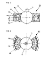
- a joint ball 15 with an integrally formed joint pin or rod is rotatably mounted in a housing 10, which consists of the two housing parts 10a, 10b.
- the housing 10 with its housing part 10b forms with the joint ball 15 a conical annular gap 1, in which 12 balls 13 are pressed so far by at least one spring that their points of contact with the joint ball 15 lie at an angle ⁇ above the radius and tan ⁇ is.
- the housing part 10b of the housing 10 receiving the joint ball 15 represents the bottom part, which is covered by the housing part 10a as an upper cover.
- the balls 13, which have a small diameter have opposite the joint ball 15 and the springs 12 represent the mechanical clamping elements for the joint ball 15.
- the balls 13 When the joint ball 15 rotates, the balls 13 are rolled as a clamping element on one side into the conical annular gap 11 and lead to a jamming of the joint ball 15 in the housing 10. By means of these balls 13, the movement of the joint ball 15 in its storage is prevented, which is achieved by the balls 13 as a mechanical element due to the self-locking effect.
- the clamping elements used can be disengaged from the outside, so that there is no longer any self-locking.
- the balls 13 are supported on a ring 18 arranged in the interior of the housing 10, which is connected to an actuating lever 16 via pins indicated at 17, so that with this actuating lever 16 the ring 18 can be displaced via the pins 17, which holds the balls 13 presses against the force of the spring 12 out of engagement in the conical annular gap 11, so that free movement of the joint balls 15 is achieved.
- the balls 13 are distributed in the conical annular gap 11, which is formed between the joint ball 15 and the cylindrical hole 11a formed in the interior of the housing 10.
- the springs 12 acting on the balls 13 represent the devices which cause elastic forces.
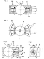
- FIGS. 4.5 and FIG 6,7 shown examples of load-inhibiting ball joint: show possibilities in which rotationally symmetrical lead to the joint ball 15 arranged clamping body for self-locking of the joint ball 15.
- the load-inhibiting ball joint 100 also consists of a housing 10 with the two housing parts 10a, 10b, of which the housing part 10b forms the bottom part and the housing part 10a forms the upper cover.
- the joint ball 15 is arranged in the interior of the housing 10.
- an annular gap 111 is formed in the interior of the housing 10, which is used to receive a number of pins 113, which are supported on their side facing away from the joint ball 15 on the inner wall surface of the housing 10 and with their other free ends on the surface of the joint ball 15 and rest on a ring 18 in the interior of the housing, which is operatively connected to pins 17 which pass through the housing wall and which are in turn connected to an actuating lever, not shown in FIG. 4, which corresponds to the actuating lever 16 in the embodiment shown in FIG 3 shown load-inhibiting ball joint 100 is formed.
- the pins 113 are also acted upon by springs 12 and together form the clamping elements.
- the pins 113 are radial, lying in one plane, i.e. lying on the ring 18, arranged around the joint ball 15.
- a number of disk segments 213 are arranged as clamping bodies which, in the same way as the pins 113, are arranged rotationally symmetrically to the joint ball 15.
- the disengagement of the load-inhibiting ball joint 100 according to FIGS. 6 and 7 corresponds otherwise to the As Installationsfrom shown in FIGS. 4 and 5.
- the disc segments 213 are also acted upon by springs 12.
- ces load-inhibiting ball joint according to Fig. 3 and 9 5 and 6.7 it is advantageous if each clamping body is loaded by a spring.
- pins 113 or disk segments 213 as clamping elements is brought about in that the pins or disk segments lie against the outer surface of the joint ball 15 and are carried along on this side when the joint ball rotates; However, they are supported on the other side on a fixed system, here the inner wall of the housing, the length between the point on the joint ball 15 and the support point increasing with an incline, the tangent of which is smaller than the coefficient of friction.
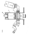
- a joint ball 15 is likewise arranged in a housing 10, the housing 10 consisting of the two parts 10a and 10b which form the recess for receiving the joint ball 15 via the rear Part 10c are connected.
- At least one rotationally symmetrical clamping body 30 is arranged in a cylindrical recess in the housing 10, which can be locked by the part 10d.
- the rotationally symmetrical clamping bodies 30 act on one side on the joint ball 15 rotatably mounted in the housing 10.
- Each clamping body 30 can be brought into and out of engagement with an adjusting body with an inner cone 31 and an outer cone 32 via a push rod indicated at 33, so that self-locking is achieved or is prevented.
- FIG. 10 An application example of a load-inhibiting ball joint 100 is shown in Fig. 10.
- a surgical microscope 50 with a microscope suspension 51 is suspended from such a load-inhibiting ball joint 100, as described above and shown in FIGS. 3 to 9.
- the actuators, such as actuating lever 16 and the push rod 33 for unlocking the self-locking device are then preferably located near the operating field next to the microscope objective and can at the same time be designed in such a way that they serve to pivot the microscope into the correct working position.
Priority Applications (1)
| Application Number | Priority Date | Filing Date | Title |
|---|---|---|---|
| AT85104918T ATE45790T1 (de) | 1985-04-18 | 1985-04-23 | Lasthemmendes gelenk, insbesondere fuer operations mikroskope, und fuer diese ausgebildete aufhaengung. |
Applications Claiming Priority (2)
| Application Number | Priority Date | Filing Date | Title |
|---|---|---|---|
| DE8511531U DE8511531U1 (de) | 1985-04-18 | 1985-04-18 | Lasthemmendes Gelenk, insbesondere Operationsmikroskope |
| DE8511531U | 1985-04-18 |
Publications (3)
| Publication Number | Publication Date |
|---|---|
| EP0198933A2 true EP0198933A2 (fr) | 1986-10-29 |
| EP0198933A3 EP0198933A3 (en) | 1987-08-19 |
| EP0198933B1 EP0198933B1 (fr) | 1989-08-23 |
Family
ID=6780089
Family Applications (1)
| Application Number | Title | Priority Date | Filing Date |
|---|---|---|---|
| EP85104918A Expired EP0198933B1 (fr) | 1985-04-18 | 1985-04-23 | Pivot avec blocage de charge, en particulier pour microscopes d'opération et suspension pour ces derniers |
Country Status (5)
| Country | Link |
|---|---|
| US (1) | US4834519A (fr) |
| EP (1) | EP0198933B1 (fr) |
| JP (1) | JPS61244343A (fr) |
| AT (1) | ATE45790T1 (fr) |
| DE (2) | DE8511531U1 (fr) |
Cited By (3)
| Publication number | Priority date | Publication date | Assignee | Title |
|---|---|---|---|---|
| EP2090917A3 (fr) * | 2008-02-18 | 2010-03-17 | Carl Zeiss Surgical GmbH | Dispositif de maintien et agencement de microscope |
| EP2338435A1 (fr) * | 2009-12-23 | 2011-06-29 | Karl Storz GmbH & Co. KG | Dispositif de retenue pour instruments médicaux |
| CN103671471A (zh) * | 2013-11-20 | 2014-03-26 | 中国航空工业集团公司北京长城计量测试技术研究所 | 一种带锁紧功能的球形万向节 |
Families Citing this family (10)
| Publication number | Priority date | Publication date | Assignee | Title |
|---|---|---|---|---|
| US5280892A (en) * | 1990-12-27 | 1994-01-25 | Smith Dresden G | Positioning fixture for welding operations |
| JPH04110216U (ja) * | 1991-03-14 | 1992-09-24 | 株式会社アイチコーポレーシヨン | ロツク保持機能付球面継手 |
| CH687641A5 (de) * | 1993-10-13 | 1997-01-15 | Max Oschwald | Sphorische Aufhaengung fuer ein technisches Instrument. |
| US5590870A (en) * | 1995-06-02 | 1997-01-07 | Advanced Machine & Engineering Co. | Universal holding system for a contoured workpiece |
| US5544968A (en) * | 1995-06-02 | 1996-08-13 | Advanced Machine & Engineering Co. | Lockable ball joint apparatus |
| DE10219970A1 (de) * | 2002-05-03 | 2003-11-13 | Zeiss Carl | Gelenkanordnung für Kabeldurchführung |
| US7365925B2 (en) * | 2006-03-30 | 2008-04-29 | Agilent Technologies, Inc. | Method of aligning optical elements |
| GB201013819D0 (en) * | 2010-08-18 | 2010-09-29 | Johnson & Allen Ltd | Articulation assembly |
| US8974372B2 (en) | 2010-08-25 | 2015-03-10 | Barry M. Fell | Path-following robot |
| CN109027587B (zh) * | 2018-10-12 | 2021-06-29 | 孙栋 | 一种大型负重相机云台 |
Citations (5)
| Publication number | Priority date | Publication date | Assignee | Title |
|---|---|---|---|---|
| US2516428A (en) * | 1947-07-01 | 1950-07-25 | Alfred A H N Scott | Releasable coupling means for connecting relatively movable parts or elements disposed about a common axis |
| FR1064065A (fr) * | 1952-10-03 | 1954-05-11 | Eloy & Cie Ets | Rotule réglable, blocable et détachable |
| DE1891958U (de) * | 1964-02-08 | 1964-04-30 | Linhof Nikolaus Karpf K G Prae | Kugelkopf fuer fotografische stative. |
| FR1373630A (fr) * | 1963-11-12 | 1964-09-25 | Schroder & Sohne Fa A | Blocage à rotule pour embout de pied d'appareil |
| GB2074337A (en) * | 1980-04-15 | 1981-10-28 | Univ Technology | Adjustable support for an optical or other instrument |
Family Cites Families (8)
| Publication number | Priority date | Publication date | Assignee | Title |
|---|---|---|---|---|
| GB291547A (en) * | 1927-03-14 | 1928-06-07 | Henry Edmund Mathews | Improvements in ball and socket joints for electric light and other like pendants |
| FR722451A (fr) * | 1931-08-29 | 1932-03-17 | Articulation réglable pour support | |
| GB449488A (en) * | 1935-02-05 | 1936-06-29 | Kaj Albrecht Nicolaj Nielsen | Improvements in and relating to ball joints, preferably for employment in connection with electric lamps |
| US2089439A (en) * | 1936-01-25 | 1937-08-10 | Eastman Kodak Co | Adjustable tripod head |
| US2161718A (en) * | 1938-06-15 | 1939-06-06 | Ralph E Miller | Leveling device |
| US2696392A (en) * | 1952-09-18 | 1954-12-07 | Ralph N Case | Ball-and-socket type trailer hitch |
| US2967458A (en) * | 1957-05-16 | 1961-01-10 | Jr William Stone | Instrument for use by a surgeon in viewing the field of operation under magnification |
| JPS5447956A (en) * | 1977-09-24 | 1979-04-16 | Hideo Arakawa | Universal retainer and universal retaining device |
-
1985
- 1985-04-18 DE DE8511531U patent/DE8511531U1/de not_active Expired
- 1985-04-23 AT AT85104918T patent/ATE45790T1/de active
- 1985-04-23 DE DE8585104918T patent/DE3572524D1/de not_active Expired
- 1985-04-23 EP EP85104918A patent/EP0198933B1/fr not_active Expired
- 1985-12-11 US US06/807,561 patent/US4834519A/en not_active Expired - Fee Related
-
1986
- 1986-04-17 JP JP61089188A patent/JPS61244343A/ja active Pending
Patent Citations (5)
| Publication number | Priority date | Publication date | Assignee | Title |
|---|---|---|---|---|
| US2516428A (en) * | 1947-07-01 | 1950-07-25 | Alfred A H N Scott | Releasable coupling means for connecting relatively movable parts or elements disposed about a common axis |
| FR1064065A (fr) * | 1952-10-03 | 1954-05-11 | Eloy & Cie Ets | Rotule réglable, blocable et détachable |
| FR1373630A (fr) * | 1963-11-12 | 1964-09-25 | Schroder & Sohne Fa A | Blocage à rotule pour embout de pied d'appareil |
| DE1891958U (de) * | 1964-02-08 | 1964-04-30 | Linhof Nikolaus Karpf K G Prae | Kugelkopf fuer fotografische stative. |
| GB2074337A (en) * | 1980-04-15 | 1981-10-28 | Univ Technology | Adjustable support for an optical or other instrument |
Cited By (3)
| Publication number | Priority date | Publication date | Assignee | Title |
|---|---|---|---|---|
| EP2090917A3 (fr) * | 2008-02-18 | 2010-03-17 | Carl Zeiss Surgical GmbH | Dispositif de maintien et agencement de microscope |
| EP2338435A1 (fr) * | 2009-12-23 | 2011-06-29 | Karl Storz GmbH & Co. KG | Dispositif de retenue pour instruments médicaux |
| CN103671471A (zh) * | 2013-11-20 | 2014-03-26 | 中国航空工业集团公司北京长城计量测试技术研究所 | 一种带锁紧功能的球形万向节 |
Also Published As
| Publication number | Publication date |
|---|---|
| DE3572524D1 (en) | 1989-09-28 |
| EP0198933B1 (fr) | 1989-08-23 |
| JPS61244343A (ja) | 1986-10-30 |
| DE8511531U1 (de) | 1985-08-22 |
| EP0198933A3 (en) | 1987-08-19 |
| ATE45790T1 (de) | 1989-09-15 |
| US4834519A (en) | 1989-05-30 |
Similar Documents
| Publication | Publication Date | Title |
|---|---|---|
| DE60009215T2 (de) | Türscharnier mit integriertem Türfeststeller für Kraftwagen | |
| DE60009659T2 (de) | Gelenk, insbesondere ein türscharnier, mit einer einrichtung zur feststellung eines ersten bewegungselementes | |
| EP0198933A2 (fr) | Pivot avec blocage de charge, en particulier pour microscopes d'opération et suspension pour ces derniers | |
| DE4333207A1 (de) | Industrieroboter | |
| EP0916798B1 (fr) | Dispositif de support pour panneaux de construction | |
| EP1714058A2 (fr) | Dispositif de verrouillage pour fixer un couvercle | |
| CH690210A5 (de) | Kompensations-Vorrichtung zum Ausgleich eines drehwinkelabhängigen Drehmomentes und medizinisches Stativ mit einer derartigen Kompensations-Vorrichtung. | |
| EP2706032B1 (fr) | Dispositif de réception de charge, en particulier moufle inférieure pour un appareil de levage | |
| DE2736386C3 (de) | Reibrollgetriebe zum Umwandeln einer Drehbewegung in eine Längsbewegung | |
| DE3615985A1 (de) | Vorrichtung zum abstoppen einer achse oder dergleichen | |
| WO2002053965A1 (fr) | Tete de trepied d'un appareil photo avec equilibrage de poids | |
| EP0114327B1 (fr) | Rotule sans jeu, en particulier pour dispositifs d'essai et ensemble rotule comportant de telles rotules | |
| DE3319813A1 (de) | Triebstock-verstellvorrichtung, insbesondere fuer neigungsverstellung von kraftfahrzeugsitzen | |
| DE3006161C2 (de) | Getriebegelenk in Tripod-Bauart | |
| DE4314549A1 (de) | Fahrzeug-Rückspiegel | |
| DE1809460C3 (de) | Türfeststeller, insbesondere für Kraftwagentüren | |
| DE8520723U1 (de) | Aufhängung für Operationsmikroskope | |
| DE3235177A1 (de) | Ecklager eines drehkippfluegels | |
| DE102012013566A1 (de) | Verbindungseinrichtung | |
| CH625572A5 (fr) | ||
| EP3917804B1 (fr) | Mécanisme de réglage de la vue | |
| DE102020123428B3 (de) | Aufnahmevorrichtung für eine Kantenbandrolle | |
| AT372483B (de) | Ecklager eines drehkippfluegels | |
| EP3623267B9 (fr) | Dispositif de réglage d'un premier composant et d'un deuxième composant d'un moyen de transport des personnes et / ou des marchandises relatives les unes aux autres ainsi que moyen de transport des personnes et / ou des marchandises doté d'un tel dispositif | |
| DE102017106793B4 (de) | Interieuranordnung für ein Kraftfahrzeug |
Legal Events
| Date | Code | Title | Description |
|---|---|---|---|
| PUAI | Public reference made under article 153(3) epc to a published international application that has entered the european phase |
Free format text: ORIGINAL CODE: 0009012 |
|
| AK | Designated contracting states |
Kind code of ref document: A2 Designated state(s): AT BE CH DE FR GB IT LI LU NL SE |
|
| PUAL | Search report despatched |
Free format text: ORIGINAL CODE: 0009013 |
|
| AK | Designated contracting states |
Kind code of ref document: A3 Designated state(s): AT BE CH DE FR GB IT LI LU NL SE |
|
| 17P | Request for examination filed |
Effective date: 19870806 |
|
| 17Q | First examination report despatched |
Effective date: 19880629 |
|
| GRAA | (expected) grant |
Free format text: ORIGINAL CODE: 0009210 |
|
| AK | Designated contracting states |
Kind code of ref document: B1 Designated state(s): AT BE CH DE FR GB IT LI LU NL SE |
|
| PG25 | Lapsed in a contracting state [announced via postgrant information from national office to epo] |
Ref country code: SE Effective date: 19890823 Ref country code: NL Effective date: 19890823 Ref country code: IT Free format text: LAPSE BECAUSE OF FAILURE TO SUBMIT A TRANSLATION OF THE DESCRIPTION OR TO PAY THE FEE WITHIN THE PRESCRIBED TIME-LIMIT;WARNING: LAPSES OF ITALIAN PATENTS WITH EFFECTIVE DATE BEFORE 2007 MAY HAVE OCCURRED AT ANY TIME BEFORE 2007. THE CORRECT EFFECTIVE DATE MAY BE DIFFERENT FROM THE ONE RECORDED. Effective date: 19890823 Ref country code: GB Effective date: 19890823 Ref country code: FR Free format text: THE PATENT HAS BEEN ANNULLED BY A DECISION OF A NATIONAL AUTHORITY Effective date: 19890823 Ref country code: BE Effective date: 19890823 |
|
| REF | Corresponds to: |
Ref document number: 45790 Country of ref document: AT Date of ref document: 19890915 Kind code of ref document: T |
|
| REF | Corresponds to: |
Ref document number: 3572524 Country of ref document: DE Date of ref document: 19890928 |
|
| EN | Fr: translation not filed | ||
| NLV1 | Nl: lapsed or annulled due to failure to fulfill the requirements of art. 29p and 29m of the patents act | ||
| GBV | Gb: ep patent (uk) treated as always having been void in accordance with gb section 77(7)/1977 [no translation filed] | ||
| PG25 | Lapsed in a contracting state [announced via postgrant information from national office to epo] |
Ref country code: AT Effective date: 19900423 |
|
| PG25 | Lapsed in a contracting state [announced via postgrant information from national office to epo] |
Ref country code: LU Free format text: LAPSE BECAUSE OF NON-PAYMENT OF DUE FEES Effective date: 19900430 Ref country code: LI Effective date: 19900430 Ref country code: CH Effective date: 19900430 |
|
| PGFP | Annual fee paid to national office [announced via postgrant information from national office to epo] |
Ref country code: DE Payment date: 19900504 Year of fee payment: 6 |
|
| PLBE | No opposition filed within time limit |
Free format text: ORIGINAL CODE: 0009261 |
|
| STAA | Information on the status of an ep patent application or granted ep patent |
Free format text: STATUS: NO OPPOSITION FILED WITHIN TIME LIMIT |
|
| 26N | No opposition filed | ||
| REG | Reference to a national code |
Ref country code: CH Ref legal event code: PL |
|
| PG25 | Lapsed in a contracting state [announced via postgrant information from national office to epo] |
Ref country code: DE Effective date: 19920201 |