EP0198933A2 - Load restraining pivot, especially for operation microscopes and suspension therefor - Google Patents
Load restraining pivot, especially for operation microscopes and suspension therefor Download PDFInfo
- Publication number
- EP0198933A2 EP0198933A2 EP85104918A EP85104918A EP0198933A2 EP 0198933 A2 EP0198933 A2 EP 0198933A2 EP 85104918 A EP85104918 A EP 85104918A EP 85104918 A EP85104918 A EP 85104918A EP 0198933 A2 EP0198933 A2 EP 0198933A2
- Authority
- EP
- European Patent Office
- Prior art keywords
- joint
- joint ball
- locking
- self
- clamping elements
- Prior art date
- Legal status (The legal status is an assumption and is not a legal conclusion. Google has not performed a legal analysis and makes no representation as to the accuracy of the status listed.)
- Granted
Links
Images

Classifications
-
- G—PHYSICS
- G02—OPTICS
- G02B—OPTICAL ELEMENTS, SYSTEMS OR APPARATUS
- G02B21/00—Microscopes
- G02B21/24—Base structure
-
- A—HUMAN NECESSITIES
- A61—MEDICAL OR VETERINARY SCIENCE; HYGIENE
- A61B—DIAGNOSIS; SURGERY; IDENTIFICATION
- A61B90/00—Instruments, implements or accessories specially adapted for surgery or diagnosis and not covered by any of the groups A61B1/00 - A61B50/00, e.g. for luxation treatment or for protecting wound edges
- A61B90/50—Supports for surgical instruments, e.g. articulated arms
-
- B—PERFORMING OPERATIONS; TRANSPORTING
- B23—MACHINE TOOLS; METAL-WORKING NOT OTHERWISE PROVIDED FOR
- B23Q—DETAILS, COMPONENTS, OR ACCESSORIES FOR MACHINE TOOLS, e.g. ARRANGEMENTS FOR COPYING OR CONTROLLING; MACHINE TOOLS IN GENERAL CHARACTERISED BY THE CONSTRUCTION OF PARTICULAR DETAILS OR COMPONENTS; COMBINATIONS OR ASSOCIATIONS OF METAL-WORKING MACHINES, NOT DIRECTED TO A PARTICULAR RESULT
- B23Q1/00—Members which are comprised in the general build-up of a form of machine, particularly relatively large fixed members
- B23Q1/25—Movable or adjustable work or tool supports
- B23Q1/26—Movable or adjustable work or tool supports characterised by constructional features relating to the co-operation of relatively movable members; Means for preventing relative movement of such members
- B23Q1/28—Means for securing sliding members in any desired position
-
- B—PERFORMING OPERATIONS; TRANSPORTING
- B23—MACHINE TOOLS; METAL-WORKING NOT OTHERWISE PROVIDED FOR
- B23Q—DETAILS, COMPONENTS, OR ACCESSORIES FOR MACHINE TOOLS, e.g. ARRANGEMENTS FOR COPYING OR CONTROLLING; MACHINE TOOLS IN GENERAL CHARACTERISED BY THE CONSTRUCTION OF PARTICULAR DETAILS OR COMPONENTS; COMBINATIONS OR ASSOCIATIONS OF METAL-WORKING MACHINES, NOT DIRECTED TO A PARTICULAR RESULT
- B23Q1/00—Members which are comprised in the general build-up of a form of machine, particularly relatively large fixed members
- B23Q1/25—Movable or adjustable work or tool supports
- B23Q1/44—Movable or adjustable work or tool supports using particular mechanisms
- B23Q1/50—Movable or adjustable work or tool supports using particular mechanisms with rotating pairs only, the rotating pairs being the first two elements of the mechanism
- B23Q1/54—Movable or adjustable work or tool supports using particular mechanisms with rotating pairs only, the rotating pairs being the first two elements of the mechanism two rotating pairs only
- B23Q1/545—Movable or adjustable work or tool supports using particular mechanisms with rotating pairs only, the rotating pairs being the first two elements of the mechanism two rotating pairs only comprising spherical surfaces
-
- F—MECHANICAL ENGINEERING; LIGHTING; HEATING; WEAPONS; BLASTING
- F16—ENGINEERING ELEMENTS AND UNITS; GENERAL MEASURES FOR PRODUCING AND MAINTAINING EFFECTIVE FUNCTIONING OF MACHINES OR INSTALLATIONS; THERMAL INSULATION IN GENERAL
- F16C—SHAFTS; FLEXIBLE SHAFTS; ELEMENTS OR CRANKSHAFT MECHANISMS; ROTARY BODIES OTHER THAN GEARING ELEMENTS; BEARINGS
- F16C11/00—Pivots; Pivotal connections
- F16C11/04—Pivotal connections
- F16C11/10—Arrangements for locking
- F16C11/103—Arrangements for locking frictionally clamped
- F16C11/106—Arrangements for locking frictionally clamped for ball joints
-
- F—MECHANICAL ENGINEERING; LIGHTING; HEATING; WEAPONS; BLASTING
- F16—ENGINEERING ELEMENTS AND UNITS; GENERAL MEASURES FOR PRODUCING AND MAINTAINING EFFECTIVE FUNCTIONING OF MACHINES OR INSTALLATIONS; THERMAL INSULATION IN GENERAL
- F16M—FRAMES, CASINGS OR BEDS OF ENGINES, MACHINES OR APPARATUS, NOT SPECIFIC TO ENGINES, MACHINES OR APPARATUS PROVIDED FOR ELSEWHERE; STANDS; SUPPORTS
- F16M11/00—Stands or trestles as supports for apparatus or articles placed thereon Stands for scientific apparatus such as gravitational force meters
- F16M11/02—Heads
- F16M11/04—Means for attachment of apparatus; Means allowing adjustment of the apparatus relatively to the stand
- F16M11/06—Means for attachment of apparatus; Means allowing adjustment of the apparatus relatively to the stand allowing pivoting
- F16M11/12—Means for attachment of apparatus; Means allowing adjustment of the apparatus relatively to the stand allowing pivoting in more than one direction
- F16M11/14—Means for attachment of apparatus; Means allowing adjustment of the apparatus relatively to the stand allowing pivoting in more than one direction with ball-joint
-
- F—MECHANICAL ENGINEERING; LIGHTING; HEATING; WEAPONS; BLASTING
- F16—ENGINEERING ELEMENTS AND UNITS; GENERAL MEASURES FOR PRODUCING AND MAINTAINING EFFECTIVE FUNCTIONING OF MACHINES OR INSTALLATIONS; THERMAL INSULATION IN GENERAL
- F16M—FRAMES, CASINGS OR BEDS OF ENGINES, MACHINES OR APPARATUS, NOT SPECIFIC TO ENGINES, MACHINES OR APPARATUS PROVIDED FOR ELSEWHERE; STANDS; SUPPORTS
- F16M13/00—Other supports for positioning apparatus or articles; Means for steadying hand-held apparatus or articles
- F16M13/02—Other supports for positioning apparatus or articles; Means for steadying hand-held apparatus or articles for supporting on, or attaching to, an object, e.g. tree, gate, window-frame, cycle
- F16M13/027—Ceiling supports
-
- A—HUMAN NECESSITIES
- A61—MEDICAL OR VETERINARY SCIENCE; HYGIENE
- A61B—DIAGNOSIS; SURGERY; IDENTIFICATION
- A61B90/00—Instruments, implements or accessories specially adapted for surgery or diagnosis and not covered by any of the groups A61B1/00 - A61B50/00, e.g. for luxation treatment or for protecting wound edges
- A61B90/50—Supports for surgical instruments, e.g. articulated arms
- A61B2090/508—Supports for surgical instruments, e.g. articulated arms with releasable brake mechanisms
-
- F—MECHANICAL ENGINEERING; LIGHTING; HEATING; WEAPONS; BLASTING
- F16—ENGINEERING ELEMENTS AND UNITS; GENERAL MEASURES FOR PRODUCING AND MAINTAINING EFFECTIVE FUNCTIONING OF MACHINES OR INSTALLATIONS; THERMAL INSULATION IN GENERAL
- F16C—SHAFTS; FLEXIBLE SHAFTS; ELEMENTS OR CRANKSHAFT MECHANISMS; ROTARY BODIES OTHER THAN GEARING ELEMENTS; BEARINGS
- F16C2322/00—Apparatus used in shaping articles
- F16C2322/39—General build up of machine tools, e.g. spindles, slides, actuators
-
- F—MECHANICAL ENGINEERING; LIGHTING; HEATING; WEAPONS; BLASTING
- F16—ENGINEERING ELEMENTS AND UNITS; GENERAL MEASURES FOR PRODUCING AND MAINTAINING EFFECTIVE FUNCTIONING OF MACHINES OR INSTALLATIONS; THERMAL INSULATION IN GENERAL
- F16M—FRAMES, CASINGS OR BEDS OF ENGINES, MACHINES OR APPARATUS, NOT SPECIFIC TO ENGINES, MACHINES OR APPARATUS PROVIDED FOR ELSEWHERE; STANDS; SUPPORTS
- F16M2200/00—Details of stands or supports
- F16M2200/04—Balancing means
- F16M2200/041—Balancing means for balancing rotational movement of the head
-
- Y—GENERAL TAGGING OF NEW TECHNOLOGICAL DEVELOPMENTS; GENERAL TAGGING OF CROSS-SECTIONAL TECHNOLOGIES SPANNING OVER SEVERAL SECTIONS OF THE IPC; TECHNICAL SUBJECTS COVERED BY FORMER USPC CROSS-REFERENCE ART COLLECTIONS [XRACs] AND DIGESTS
- Y10—TECHNICAL SUBJECTS COVERED BY FORMER USPC
- Y10T—TECHNICAL SUBJECTS COVERED BY FORMER US CLASSIFICATION
- Y10T403/00—Joints and connections
- Y10T403/32—Articulated members
- Y10T403/32254—Lockable at fixed position
- Y10T403/32262—At selected angle
- Y10T403/32311—Ball and socket
Definitions
- the invention relates to a load-inhibiting joint, in particular for surgical microscopes, and to a suspension designed for this.
- Load-inhibiting rotary and sliding joints as shown in Fig. La, lb and Fig. 2, are known.
- the function of these joints is only effective in one plane or around an axis.
- the invention solves the problem of creating a spatially acting, load-inhibiting joint, in particular for surgical microscopes, which can be produced economically without great technical outlay and can be used as a surgical microscope suspension.
- a load-inhibiting joint in particular for surgical microscopes, which is designed according to the invention in such a way that the joint consists of a joint ball mounted in a housing with an integrally formed joint pin or rod, which in its mounting by mechanical clamping elements in their freedom of movement can be inhibited.
- the load-inhibiting ball-and-socket joint is used when a position of a part or device that has been set should be maintained and, on the other hand, when the load inhibition is lifted, easy spatial adjustability should be possible.
- the load-inhibiting ball joint has a simple construction and is economical to manufacture.
- the use of the load-inhibiting ball joint as a suspension for surgical microscopes is particularly suitable, in which case the actuators for unlocking the self-locking device are attached near the surgical field next to the microscope objective and at the same time serve to pivot the microscope into the correct working position.
- a joint ball 15 with an integrally formed joint pin or rod is rotatably mounted in a housing 10, which consists of the two housing parts 10a, 10b.
- the housing 10 with its housing part 10b forms with the joint ball 15 a conical annular gap 1, in which 12 balls 13 are pressed so far by at least one spring that their points of contact with the joint ball 15 lie at an angle ⁇ above the radius and tan ⁇ is.
- the housing part 10b of the housing 10 receiving the joint ball 15 represents the bottom part, which is covered by the housing part 10a as an upper cover.
- the balls 13, which have a small diameter have opposite the joint ball 15 and the springs 12 represent the mechanical clamping elements for the joint ball 15.
- the balls 13 When the joint ball 15 rotates, the balls 13 are rolled as a clamping element on one side into the conical annular gap 11 and lead to a jamming of the joint ball 15 in the housing 10. By means of these balls 13, the movement of the joint ball 15 in its storage is prevented, which is achieved by the balls 13 as a mechanical element due to the self-locking effect.
- the clamping elements used can be disengaged from the outside, so that there is no longer any self-locking.
- the balls 13 are supported on a ring 18 arranged in the interior of the housing 10, which is connected to an actuating lever 16 via pins indicated at 17, so that with this actuating lever 16 the ring 18 can be displaced via the pins 17, which holds the balls 13 presses against the force of the spring 12 out of engagement in the conical annular gap 11, so that free movement of the joint balls 15 is achieved.
- the balls 13 are distributed in the conical annular gap 11, which is formed between the joint ball 15 and the cylindrical hole 11a formed in the interior of the housing 10.
- the springs 12 acting on the balls 13 represent the devices which cause elastic forces.
- FIGS. 4.5 and FIG 6,7 shown examples of load-inhibiting ball joint: show possibilities in which rotationally symmetrical lead to the joint ball 15 arranged clamping body for self-locking of the joint ball 15.
- the load-inhibiting ball joint 100 also consists of a housing 10 with the two housing parts 10a, 10b, of which the housing part 10b forms the bottom part and the housing part 10a forms the upper cover.
- the joint ball 15 is arranged in the interior of the housing 10.
- an annular gap 111 is formed in the interior of the housing 10, which is used to receive a number of pins 113, which are supported on their side facing away from the joint ball 15 on the inner wall surface of the housing 10 and with their other free ends on the surface of the joint ball 15 and rest on a ring 18 in the interior of the housing, which is operatively connected to pins 17 which pass through the housing wall and which are in turn connected to an actuating lever, not shown in FIG. 4, which corresponds to the actuating lever 16 in the embodiment shown in FIG 3 shown load-inhibiting ball joint 100 is formed.
- the pins 113 are also acted upon by springs 12 and together form the clamping elements.
- the pins 113 are radial, lying in one plane, i.e. lying on the ring 18, arranged around the joint ball 15.
- a number of disk segments 213 are arranged as clamping bodies which, in the same way as the pins 113, are arranged rotationally symmetrically to the joint ball 15.
- the disengagement of the load-inhibiting ball joint 100 according to FIGS. 6 and 7 corresponds otherwise to the As Installationsfrom shown in FIGS. 4 and 5.
- the disc segments 213 are also acted upon by springs 12.
- ces load-inhibiting ball joint according to Fig. 3 and 9 5 and 6.7 it is advantageous if each clamping body is loaded by a spring.
- pins 113 or disk segments 213 as clamping elements is brought about in that the pins or disk segments lie against the outer surface of the joint ball 15 and are carried along on this side when the joint ball rotates; However, they are supported on the other side on a fixed system, here the inner wall of the housing, the length between the point on the joint ball 15 and the support point increasing with an incline, the tangent of which is smaller than the coefficient of friction.
- a joint ball 15 is likewise arranged in a housing 10, the housing 10 consisting of the two parts 10a and 10b which form the recess for receiving the joint ball 15 via the rear Part 10c are connected.
- At least one rotationally symmetrical clamping body 30 is arranged in a cylindrical recess in the housing 10, which can be locked by the part 10d.
- the rotationally symmetrical clamping bodies 30 act on one side on the joint ball 15 rotatably mounted in the housing 10.
- Each clamping body 30 can be brought into and out of engagement with an adjusting body with an inner cone 31 and an outer cone 32 via a push rod indicated at 33, so that self-locking is achieved or is prevented.
- FIG. 10 An application example of a load-inhibiting ball joint 100 is shown in Fig. 10.
- a surgical microscope 50 with a microscope suspension 51 is suspended from such a load-inhibiting ball joint 100, as described above and shown in FIGS. 3 to 9.
- the actuators, such as actuating lever 16 and the push rod 33 for unlocking the self-locking device are then preferably located near the operating field next to the microscope objective and can at the same time be designed in such a way that they serve to pivot the microscope into the correct working position.
Abstract
Description
Die Erfindung betrifft ein lasthemmendes Gelenk, insbesondere für Operationsmikroskope, und für diese ausgebildete Aufhängung.The invention relates to a load-inhibiting joint, in particular for surgical microscopes, and to a suspension designed for this.
Lasthemmende Dreh- und Schubgelenke, wie in Fig. la,lb und Fig. 2 dargestellt, sind bekannt. Die Funktion dieser Gelenke ist nur in einer Ebene oder um eine Achse wirksam.Load-inhibiting rotary and sliding joints, as shown in Fig. La, lb and Fig. 2, are known. The function of these joints is only effective in one plane or around an axis.
Die Erfindung löst die Aufgabe, ein räumlich wirkendes, lasthemmendes Gelenk, insbesondere für Operationsmikroskope, zu schaffen, welches ohne großen technischen Aufwand wirtschaftlich herstellbar und als Operationsmikroskopaufhängung einsetzbar ist.The invention solves the problem of creating a spatially acting, load-inhibiting joint, in particular for surgical microscopes, which can be produced economically without great technical outlay and can be used as a surgical microscope suspension.
Zur Lösung dieser Aufgabe wird ein lasthemmendes Gelenk, insbesondere für Operationsmikroskope, vorgeschlagen, das erfindungsgemäß in der Weise ausgebildet ist, daß das Gelenk aus einer in einen Gehäuse gelagerten Gelenkkugel mit einem angeformten Gelenkzapfen oder -stange besteht, die in ihrer Lagerung durch mechanische Klemmelemente in ihrer freien Beweglichkeit hemmbar ist.To solve this problem, a load-inhibiting joint, in particular for surgical microscopes, is proposed, which is designed according to the invention in such a way that the joint consists of a joint ball mounted in a housing with an integrally formed joint pin or rod, which in its mounting by mechanical clamping elements in their freedom of movement can be inhibited.
Bei einem derart ausgebildetem lasthemmenden Kugelgelenk wird die Selbsthemmung dadurch bewirkt, daß die Klemmelemente an der GelenkkugelflächE anliegen und, soweit es sich um Klemmelemente in Form von Stiften oder Scheibensegmenten handelt, bei der Dreting der Gelenkkugel an dieser Seite mitgenommen werden sich jedoch an der anderenIn a load-inhibiting ball joint designed in this way, the self-locking is brought about by the fact that the clamping elements rest against the joint ball surface E and, as far as clamping elements in the form of pins or disk segments are concerned, the dretting of the joint ball on this side is carried along on the other
Seite an einer festen Anlage abstützen, wobei dabei die Länge zwischen dem Punkt auf der Gelenkkugel und dem Abstützpunkt mit einer Steigung zunimmt, dessen Tangens kleiner als die Reibzahl ist.Support side on a fixed system, whereby the length between the point on the joint ball and the support point increases with an incline, the tangent of which is smaller than the coefficient of friction.
Das lasthemmende Kugelgelenk kommt zur Anwendung, wenn eine einmal eingestellte Lage eines Teiles oder Gerätes beibehalten werden soll und wenn andererseits bei Aufhebung der Lasthemmung eine leichte räumliche Verstellbarkeit möglich sein soll.The load-inhibiting ball-and-socket joint is used when a position of a part or device that has been set should be maintained and, on the other hand, when the load inhibition is lifted, easy spatial adjustability should be possible.
Das lasthemmende Kugelgelenk weist eine einfache Bauweise auf und ist wirtschaftlich herstellbar. Besonders geeignet ist die Verwendung des lasthemmenden Kugelgelenkes als Aufhängung für Operationsmikroskope, wobei dann die Betätigungsorgane für die Entriegelung der Selbsthemmung in der Nähe des Operationsfeldes neben dem Mikroskopobjektiv angebracht sind und gleichzeitig dazu dienen, das Mikroskop in die richtige Arbeitsstellung zu schwenken.The load-inhibiting ball joint has a simple construction and is economical to manufacture. The use of the load-inhibiting ball joint as a suspension for surgical microscopes is particularly suitable, in which case the actuators for unlocking the self-locking device are attached near the surgical field next to the microscope objective and at the same time serve to pivot the microscope into the correct working position.
Weitere vorteilhafte Ausgestaltungen der Erfindung sind in den Unteransprüchen gekennzeichnet, wobei eine weitere Lösung der gestellten Aufgabe in einer Operationsmikroskopaufhängung besteht, die entsprechend der Ansprüche 9 bis 16 aus einem lasthemmenden Kugelgelenk besteht.Further advantageous refinements of the invention are characterized in the subclaims, a further solution to the problem consisting in a surgical microscope suspension which, according to claims 9 to 16, consists of a load-inhibiting ball joint.
Im folgenden wird der Gegenstand der Erfindung in den Zeichnungen erläutert. Es zeigt
- Fig. la und lb in einem senkrechten Längsschnitt ein lasthemmendes Drehgelenk in einer Ansicht von vorn mit abschnittsweise entfernter Abdeckung,
- Fig. 2 in einem senkrechten Längsschnitt ein lasthemmendes Schubgelenk,
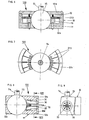
- Fig. 3 teils in Ansicht, teils in einem senkrechten Schnitt ein lasthemmendes Kugelgelenk,
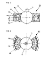
- Fig. 4 teils in Ansicht, teils in einem senkrechten Schnitt ein lasthemmendes Kugelgelenk mit auf die Gelenkkugel einwirkenden Stiften als Klemmelemente,
- Fig. 5 in einer Ansicht von oben das Kugelgelenk nach Fig. 4,
- Fig. 6 teils in Ansicht, teils in einem senkrechten Schnitt ein lasthemmendes Kugelgelenk mit auf die Gelenkkugel einwirkenden Scheibensegmenten als Klemmelemente,
- Fig. 7 in einer Ansicht von oben das Kugelgelenk nach Fig. 6,
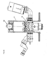
- Fig. 8 teils in Ansicht, teils in einem senkrechten Schnitt ein lasthemmendes Kugelgelenk mit einem auf die Gelenkkugel einseitig einwirkenden Klemmelement,
- Fig. 9 einen senkrechten Schnitt gemäß Linie VIII-VIII in Fig. 8 und
- Fig. 10 in einer Vorderansicht ein in einem selbsthemmenden Kugelgelenk aufgehängtes Operationsmikroskop.
- La and lb in a vertical longitudinal section a load-inhibiting swivel in a view from the front with sections of the cover removed,
- 2 in a vertical longitudinal section a load-inhibiting thrust joint,
- 3 partly in view, partly in a vertical section, a load-inhibiting ball joint,
- 4 partly in view, partly in a vertical section, a load-inhibiting ball joint with pins acting on the joint ball as clamping elements,
- F ig. 5 in a view from above the ball joint according to FIG. 4,
- 6, partly in view, partly in a vertical section, a load-inhibiting ball joint with disc segments acting on the joint ball as clamping elements,
- 7 is a top view of the ball joint of FIG. 6,
- 8 partly in view, partly in a vertical section, a load-inhibiting ball joint with a clamping element acting on one side on the joint ball,
- Fig. 9 is a vertical section along line VIII-VIII in Fig. 8 and
- Fig. 10 is a front view of a surgical microscope suspended in a self-locking ball joint.
Bei dem in Fig. 3 dargestellten und mit 100 bezeichneten lasthemmenden Kugelgelenk ist in einem Gehäuse 10, welches aus den beiden Gehäuseteilen 10a, 10b besteht, eine Gelenkkugel 15 mit einem angeformten Gelenkzapfen bzw. -stange drehbar gelagert. Das Gehäuse 10 mit seinem Gehäuseteil 10b bildet mit der Gelenkkugel 15 einen konischen Ringspalt 1, in dem von mindestens einer Feder 12 Kugeln 13 soweit iineingedrückt werden, daß ihre Berührungspunkte mit ler Gelenkkugel 15 unter einem Winkel α über dem Halbmesser liegen und tan α≤µ ist. Das Gehäuseteil 10b des die Gelenkugel 15 aufnehmenden Gehäuses 10 stellt das Bodenteil dar, das von dem Gehäuseteil 10a als obere Abdeckung abgedeckt ist. Die Kugeln 13, die einen kleinen Durchmesser gegenüber der Gelenkkugel 15 aufweisen und die Federn 12 stellen die mechanischen Klemmelemente für die Gelenkkugel 15 dar.In the load-inhibiting ball joint shown in FIG. 3 and designated 100, a
Bei einer Drehung der Gelenkkugel 15 werden die Kugeln 13 als Klemmelement auf einer Seite in den konischen Ringspalt 11 hineingerollt und führen zu einem Verklemmen der Gelenkkugel 15 in dem Gehäuse 10. Mittels dieser Kugeln 13 wird die Bewegung der Gelenkkugel 15 in ihrer Lagerung verhindert, was durch die Kugeln 13 als mechanisches Element aufgrund der erwirkten Selbsthemmung erreicht wird.When the
Die verwendeten Klemmelemente können von außen außer Eingriff gebracht werden, so daß dann keine Selbsthemmung mehr gegeben ist. Hierzu sind die Kugeln 13 auf einem im Innenraum des Gehäuses 10 angeordneten Ring 18 abgestützt, der über bei 17 angedeutete Stifte mit einem Betätigungshebel 16 in Verbindung steht, so daß mit diesem Betätigungshebel 16 über die Stifte 17 der Ring 18 verschiebbar ist, der die Kugeln 13 gegen die Kraft der Feder 12 aus dem Eingriff in dem konischen Ringspalt 11 drückt, so daß eine freie Beweglichkeit der Gelenkkugeln 15 erreicht wird.The clamping elements used can be disengaged from the outside, so that there is no longer any self-locking. For this purpose, the
Die Anordnung der Kugeln 13 erfolgt verteilt in dem konischen Ringspalt 11, der zwischen der Gelenkkugel 15 und der die Gelenkkugel 15 im Innenraum des Gehäuses 10 aussgebildeten zylindrischen Bohrung lla gebildet wird. Die die Kugeln 13 beaufschlagenden Federn 12 stellen die elastische Kräfte bewirkenden Einrichtungen dar.The
Da zwischen den Kugeln 13 in dem konischen Ringspalt 11 und der Gelenkkugel 15 hohe Flächenpressungen auftreten, ist die Verwendung andersartig ausgebildeter, die Flächenpressung verringernder Körper für die Erzielung der Sell"3t-hemmung von Vorteil. Die in den Fig. 4,5 und Fig. 6,7 gezeigten Ausführungsbeispiele lasthemmender Kugelgelenk: zeigen Möglichkeiten, bei denen rotationssymmetrisch zur Gelenkkugel 15 angeordnete Klemmkörper zur Selbsthemmung der Gelenkkugel 15 führen.Since high surface pressures occur between the
Das lasthemmende Kugelgelenk 100 gemäß Fig. 4 und 5 besteht ebenfalls aus einem Gehäuse 10 mit den beiden Gehäuseteilen 10a, 10b, von denen das Gehäuseteil 10b das Bodenteil und das Gehäuseteil 10a die obere Abdeckung bildet. Im Innenraum des Gehäuses 10 ist die Gelenkkugel 15 angeordnet. Außerdem ist im Innenraum des Gehäuses 10 ein Ringspalt 111 ausgebildet, der zur Aufnahme einer Anzahl von Stiften 113 dient, die sich auf ihrer der Gelenkkugel 15 abgewandten Seite an der Innenwandfläche des Gehäuses 10 abstützen und die mit ihren anderen freien Enden auf der Oberfläche der Gelenkkugel 15 anliegen und sich auf einem Ring 18 im Innenraum des Gehäuses abstützen, der mit durch die Gehäusewandung hindurchgeführten Stiften 17 in Wirkverbindung steht, die wiederum mit einem in Fig. 4 nicht dargestellten Betätigungshebel verbunden sind, der entsprechend dem Betätigungshebel.16 bei dem in Fig. 3 dargestellten lasthemmenden Kugelgelenk 100 ausgebildet ist.The load-inhibiting
Die Stifte 113 sind ebenfalls von Federn 12 beaufschlagt und bilden mit diesen zusammen die Klemmelemente. Außerdem sind die Stifte 113 radial, und zwar in einer Ebene liegend, d.h. auf dem Ring 18 liegend, um die Gelenkkugel 15 angeordret.The
Bei der in Fig. 6 und 7 gezeigten Ausführungsform sind anstelle von Stiften 113 als Klemmelemente um die in dem Gehäuse 10 angeordnete Gelenkkugel 15 eine Anzahl von Scheibensegmenten 213 als Klemmkörper angeordnet, die entsprechend der Stifte 113 in gleicher Weise rotationssymmetrisch zur Gelenkkugel 15 angeordnet sind. Die Ausge- scaltung des lasthemmenden Kugelgelenkes 100 gemäß Fig. 6 und 7 entspricht ansonsten der in Fig. 4 und 5 gezeigten Asführungsfrom. Die Scheibensegmente 213 sind ebenfalls von Federn 12 beaufschlagt. Bei allen Ausführungsformen ces lasthemmenden Kugelgelenkes entsprechend Fig. 3 und 9 5 und 6,7 ist es von Vorteil, wenn jeder Klemmkörper von einer Feder beaufschlagt ist.In the embodiment shown in FIGS. 6 and 7, instead of
Die Selbsthemmung unter Verwendung von Stiften 113 bzw. Scheibensegmenten 213 als Klemmelemente wird dadurch bewirkt, daß die Stifte bzw. Scheibensegmente an der Außenfläche der Gelenkkugel 15 anliegen und bei einer Drehung der Gelenkkugel an dieser Seite mitgenommen werden; sie stützen sich jedoch an der anderen Seite an einer festen Anlage, hier Gehäuseinnenwand, ab, wobei die Länge zwischen dem Punkt auf der Gelenkkugel 15 und dem Abstützpunkt mit einer Steigung zunimmt, dessen Tangens kleiner als die Reibzahl ist.The self-
Auch in den Fällen, in denen Stifte 113 oder Scheibensegmente 213 entsprechend Fig. 4,5 und Fig. 6,7 als Klemmelemente verwendet werden, wird die Selbsthemmung aufgehoben, wenn die Klemmelemente von außen über die Stifte 17 und den Ring 18 gegen die Federn 12 außer Eingriff gebracht werden.Even in the cases in which
Bei der in Fig. 8 und 9 gezeigten Ausführungsform eines lasthemmenden Kugelgelenkes ist ebenfalls in einem Gehäuse 10 eine Gelenkkugel 15 angeordnet, wobei das Gehäuse 10 aus den beiden Teilen 10a und 10b besteht, die unter Ausbildung der Ausnehmung zur Aufnahme der Gelenkkugel 15 über das rückwärtige Teil 10c verbunden sind. In einer zylindrischen Ausnehmung in dem Gehäuse 10, die durch das Teil 10d abschließbar ist, ist mindestens ein rotationssymmetrischer Klemmkörper 30 angeordnet. Die rotationssymmetrischen Klemmkörper 30 wirken einseitig auf die in dem Gehäuse 10 drehbar gelagerte Gelenkkugel 15. Jeder Klemmkörper 30 kann mit einem Stellkörper mit einem Innenkonus 31 und einem Außenkonus 32 über eine bei 33 angedeutete Schubstange in und außer Eingriff gebracht werden, so daß die Selbsthemmung erzielt oder verhindert wird.In the embodiment of a load-inhibiting ball joint shown in FIGS. 8 and 9, a
Ein Anwendungsbeispiel eines lasthemmenden Kugelgelenkes 100 ist in Fig. 10 dargestellt. Hier ist ein Operationsmikroskop 50 mit einer Mikroskopaufhängung 51 an einem derartigen lasthemmenden Kugelgelenk 100, wie voranstehend beschrieben und in Fig. 3 bis 9 dargestellt, aufgehängt. Die Betätigungsorgane, wie Betätigungshebel 16 und die Schubstange 33 für die Entriegelung der Selbsthemmung sind dann vorzugsweise in der Nähe des Operationsfeldes neben dem Mikroskopobjektiv angebracht und können gleichzeitig so ausgestaltet sein, daß sie dazu dienen, das Mikroskop in die richtige Arbeitsstellung zu schwenken.An application example of a load-inhibiting
Claims (16)
Priority Applications (1)
| Application Number | Priority Date | Filing Date | Title |
|---|---|---|---|
| AT85104918T ATE45790T1 (en) | 1985-04-18 | 1985-04-23 | LOAD-RESISTING JOINT, PARTICULARLY FOR OPERATIONS MICROSCOPES, AND FOR THIS TRAINED SUSPENSION. |
Applications Claiming Priority (2)
| Application Number | Priority Date | Filing Date | Title |
|---|---|---|---|
| DE8511531U DE8511531U1 (en) | 1985-04-18 | 1985-04-18 | Load-inhibiting joint, especially surgical microscopes |
| DE8511531U | 1985-04-18 |
Publications (3)
| Publication Number | Publication Date |
|---|---|
| EP0198933A2 true EP0198933A2 (en) | 1986-10-29 |
| EP0198933A3 EP0198933A3 (en) | 1987-08-19 |
| EP0198933B1 EP0198933B1 (en) | 1989-08-23 |
Family
ID=6780089
Family Applications (1)
| Application Number | Title | Priority Date | Filing Date |
|---|---|---|---|
| EP85104918A Expired EP0198933B1 (en) | 1985-04-18 | 1985-04-23 | Load restraining pivot, especially for operation microscopes and suspension therefor |
Country Status (5)
| Country | Link |
|---|---|
| US (1) | US4834519A (en) |
| EP (1) | EP0198933B1 (en) |
| JP (1) | JPS61244343A (en) |
| AT (1) | ATE45790T1 (en) |
| DE (2) | DE8511531U1 (en) |
Cited By (3)
| Publication number | Priority date | Publication date | Assignee | Title |
|---|---|---|---|---|
| EP2090917A3 (en) * | 2008-02-18 | 2010-03-17 | Carl Zeiss Surgical GmbH | Holding device and microscope assembly |
| EP2338435A1 (en) * | 2009-12-23 | 2011-06-29 | Karl Storz GmbH & Co. KG | Holder for medical instruments |
| CN103671471A (en) * | 2013-11-20 | 2014-03-26 | 中国航空工业集团公司北京长城计量测试技术研究所 | Universal ball joint with locking function |
Families Citing this family (10)
| Publication number | Priority date | Publication date | Assignee | Title |
|---|---|---|---|---|
| US5280892A (en) * | 1990-12-27 | 1994-01-25 | Smith Dresden G | Positioning fixture for welding operations |
| JPH04110216U (en) * | 1991-03-14 | 1992-09-24 | 株式会社アイチコーポレーシヨン | Spherical joint with lock retention function |
| CH687641A5 (en) * | 1993-10-13 | 1997-01-15 | Max Oschwald | Sphorische Aufhaengung for a technical instrument. |
| US5544968A (en) * | 1995-06-02 | 1996-08-13 | Advanced Machine & Engineering Co. | Lockable ball joint apparatus |
| US5590870A (en) * | 1995-06-02 | 1997-01-07 | Advanced Machine & Engineering Co. | Universal holding system for a contoured workpiece |
| DE10219970A1 (en) * | 2002-05-03 | 2003-11-13 | Zeiss Carl | Joint arrangement for cable entry |
| US7365925B2 (en) * | 2006-03-30 | 2008-04-29 | Agilent Technologies, Inc. | Method of aligning optical elements |
| GB201013819D0 (en) * | 2010-08-18 | 2010-09-29 | Johnson & Allen Ltd | Articulation assembly |
| US8974372B2 (en) | 2010-08-25 | 2015-03-10 | Barry M. Fell | Path-following robot |
| CN109027587B (en) * | 2018-10-12 | 2021-06-29 | 孙栋 | Large-scale camera cloud platform that bears a burden |
Citations (5)
| Publication number | Priority date | Publication date | Assignee | Title |
|---|---|---|---|---|
| US2516428A (en) * | 1947-07-01 | 1950-07-25 | Alfred A H N Scott | Releasable coupling means for connecting relatively movable parts or elements disposed about a common axis |
| FR1064065A (en) * | 1952-10-03 | 1954-05-11 | Eloy & Cie Ets | Adjustable, lockable and detachable ball head |
| DE1891958U (en) * | 1964-02-08 | 1964-04-30 | Linhof Nikolaus Karpf K G Prae | BALL HEAD FOR PHOTOGRAPHIC TRIPODS. |
| FR1373630A (en) * | 1963-11-12 | 1964-09-25 | Schroder & Sohne Fa A | Ball joint for device foot tip |
| GB2074337A (en) * | 1980-04-15 | 1981-10-28 | Univ Technology | Adjustable support for an optical or other instrument |
Family Cites Families (8)
| Publication number | Priority date | Publication date | Assignee | Title |
|---|---|---|---|---|
| GB291547A (en) * | 1927-03-14 | 1928-06-07 | Henry Edmund Mathews | Improvements in ball and socket joints for electric light and other like pendants |
| FR722451A (en) * | 1931-08-29 | 1932-03-17 | Adjustable joint for support | |
| GB449488A (en) * | 1935-02-05 | 1936-06-29 | Kaj Albrecht Nicolaj Nielsen | Improvements in and relating to ball joints, preferably for employment in connection with electric lamps |
| US2089439A (en) * | 1936-01-25 | 1937-08-10 | Eastman Kodak Co | Adjustable tripod head |
| US2161718A (en) * | 1938-06-15 | 1939-06-06 | Ralph E Miller | Leveling device |
| US2696392A (en) * | 1952-09-18 | 1954-12-07 | Ralph N Case | Ball-and-socket type trailer hitch |
| US2967458A (en) * | 1957-05-16 | 1961-01-10 | Jr William Stone | Instrument for use by a surgeon in viewing the field of operation under magnification |
| JPS5447956A (en) * | 1977-09-24 | 1979-04-16 | Hideo Arakawa | Universal retainer and universal retaining device |
-
1985
- 1985-04-18 DE DE8511531U patent/DE8511531U1/en not_active Expired
- 1985-04-23 DE DE8585104918T patent/DE3572524D1/en not_active Expired
- 1985-04-23 AT AT85104918T patent/ATE45790T1/en active
- 1985-04-23 EP EP85104918A patent/EP0198933B1/en not_active Expired
- 1985-12-11 US US06/807,561 patent/US4834519A/en not_active Expired - Fee Related
-
1986
- 1986-04-17 JP JP61089188A patent/JPS61244343A/en active Pending
Patent Citations (5)
| Publication number | Priority date | Publication date | Assignee | Title |
|---|---|---|---|---|
| US2516428A (en) * | 1947-07-01 | 1950-07-25 | Alfred A H N Scott | Releasable coupling means for connecting relatively movable parts or elements disposed about a common axis |
| FR1064065A (en) * | 1952-10-03 | 1954-05-11 | Eloy & Cie Ets | Adjustable, lockable and detachable ball head |
| FR1373630A (en) * | 1963-11-12 | 1964-09-25 | Schroder & Sohne Fa A | Ball joint for device foot tip |
| DE1891958U (en) * | 1964-02-08 | 1964-04-30 | Linhof Nikolaus Karpf K G Prae | BALL HEAD FOR PHOTOGRAPHIC TRIPODS. |
| GB2074337A (en) * | 1980-04-15 | 1981-10-28 | Univ Technology | Adjustable support for an optical or other instrument |
Cited By (3)
| Publication number | Priority date | Publication date | Assignee | Title |
|---|---|---|---|---|
| EP2090917A3 (en) * | 2008-02-18 | 2010-03-17 | Carl Zeiss Surgical GmbH | Holding device and microscope assembly |
| EP2338435A1 (en) * | 2009-12-23 | 2011-06-29 | Karl Storz GmbH & Co. KG | Holder for medical instruments |
| CN103671471A (en) * | 2013-11-20 | 2014-03-26 | 中国航空工业集团公司北京长城计量测试技术研究所 | Universal ball joint with locking function |
Also Published As
| Publication number | Publication date |
|---|---|
| ATE45790T1 (en) | 1989-09-15 |
| US4834519A (en) | 1989-05-30 |
| DE8511531U1 (en) | 1985-08-22 |
| JPS61244343A (en) | 1986-10-30 |
| EP0198933B1 (en) | 1989-08-23 |
| EP0198933A3 (en) | 1987-08-19 |
| DE3572524D1 (en) | 1989-09-28 |
Similar Documents
| Publication | Publication Date | Title |
|---|---|---|
| DE60009215T2 (en) | Door hinge with integrated door lock for motor vehicles | |
| DE60009659T2 (en) | GELENK, PARTICULARLY AN DOOR HARNESS, WITH A DEVICE FOR DETERMINING A FIRST MOVEMENT ELEMENT | |
| EP0198933A2 (en) | Load restraining pivot, especially for operation microscopes and suspension therefor | |
| DE4333207A1 (en) | Industrial robot with spring counterbalancing gravitational torque - has adjustment for spring mounting altering direction of counterbalancing torque | |
| EP0916798B1 (en) | Fixing means for building panels | |
| EP1714058A2 (en) | Locking device for fixing a lid | |
| CH690210A5 (en) | Compensating apparatus for compensating a rotational angle-dependent torque and medical tripod with such a compensation device. | |
| EP2706032B1 (en) | Load bearing device, in particular lower pulley block for a lifting device | |
| DE2736386C3 (en) | Friction roller gears for converting a rotary movement into a longitudinal movement | |
| WO2002053965A1 (en) | Balanced camera tripod head | |
| EP0114327B1 (en) | Play-free ball-joint, in particular for test-equipment and joint assembly comprising such ball-joints | |
| DE3319813A1 (en) | HEADSTOCK ADJUSTMENT, ESPECIALLY FOR TILT ADJUSTMENT OF MOTOR VEHICLE SEATS | |
| DE102007033959B4 (en) | clamping mechanism | |
| DE4314549A1 (en) | Vehicle rear view mirror | |
| DE1809460C3 (en) | Door stops, in particular for motor vehicle doors | |
| DE8520723U1 (en) | Suspension for surgical microscopes | |
| DE3235177A1 (en) | Corner bearing of a turn-and-tilt wing | |
| DE102012013566A1 (en) | connecting device | |
| CH625572A5 (en) | ||
| EP3917804B1 (en) | Vision adjusting mechanism | |
| DE102020123428B3 (en) | Pick-up device for an edgeband roll | |
| AT372483B (en) | CORNER BEARING OF A TURNTILT LEAF | |
| EP3623267B9 (en) | Device for adjusting a first component and a second component of a pedestrian and/or goods transport means relative to each other, and passenger and/or goods transport means with such a device | |
| DE102017106793B4 (en) | Interior arrangement for a motor vehicle | |
| DE3633892C2 (en) |
Legal Events
| Date | Code | Title | Description |
|---|---|---|---|
| PUAI | Public reference made under article 153(3) epc to a published international application that has entered the european phase |
Free format text: ORIGINAL CODE: 0009012 |
|
| AK | Designated contracting states |
Kind code of ref document: A2 Designated state(s): AT BE CH DE FR GB IT LI LU NL SE |
|
| PUAL | Search report despatched |
Free format text: ORIGINAL CODE: 0009013 |
|
| AK | Designated contracting states |
Kind code of ref document: A3 Designated state(s): AT BE CH DE FR GB IT LI LU NL SE |
|
| 17P | Request for examination filed |
Effective date: 19870806 |
|
| 17Q | First examination report despatched |
Effective date: 19880629 |
|
| GRAA | (expected) grant |
Free format text: ORIGINAL CODE: 0009210 |
|
| AK | Designated contracting states |
Kind code of ref document: B1 Designated state(s): AT BE CH DE FR GB IT LI LU NL SE |
|
| PG25 | Lapsed in a contracting state [announced via postgrant information from national office to epo] |
Ref country code: SE Effective date: 19890823 Ref country code: NL Effective date: 19890823 Ref country code: IT Free format text: LAPSE BECAUSE OF FAILURE TO SUBMIT A TRANSLATION OF THE DESCRIPTION OR TO PAY THE FEE WITHIN THE PRESCRIBED TIME-LIMIT;WARNING: LAPSES OF ITALIAN PATENTS WITH EFFECTIVE DATE BEFORE 2007 MAY HAVE OCCURRED AT ANY TIME BEFORE 2007. THE CORRECT EFFECTIVE DATE MAY BE DIFFERENT FROM THE ONE RECORDED. Effective date: 19890823 Ref country code: GB Effective date: 19890823 Ref country code: FR Free format text: THE PATENT HAS BEEN ANNULLED BY A DECISION OF A NATIONAL AUTHORITY Effective date: 19890823 Ref country code: BE Effective date: 19890823 |
|
| REF | Corresponds to: |
Ref document number: 45790 Country of ref document: AT Date of ref document: 19890915 Kind code of ref document: T |
|
| REF | Corresponds to: |
Ref document number: 3572524 Country of ref document: DE Date of ref document: 19890928 |
|
| EN | Fr: translation not filed | ||
| NLV1 | Nl: lapsed or annulled due to failure to fulfill the requirements of art. 29p and 29m of the patents act | ||
| GBV | Gb: ep patent (uk) treated as always having been void in accordance with gb section 77(7)/1977 [no translation filed] | ||
| PG25 | Lapsed in a contracting state [announced via postgrant information from national office to epo] |
Ref country code: AT Effective date: 19900423 |
|
| PG25 | Lapsed in a contracting state [announced via postgrant information from national office to epo] |
Ref country code: LU Free format text: LAPSE BECAUSE OF NON-PAYMENT OF DUE FEES Effective date: 19900430 Ref country code: LI Effective date: 19900430 Ref country code: CH Effective date: 19900430 |
|
| PGFP | Annual fee paid to national office [announced via postgrant information from national office to epo] |
Ref country code: DE Payment date: 19900504 Year of fee payment: 6 |
|
| PLBE | No opposition filed within time limit |
Free format text: ORIGINAL CODE: 0009261 |
|
| STAA | Information on the status of an ep patent application or granted ep patent |
Free format text: STATUS: NO OPPOSITION FILED WITHIN TIME LIMIT |
|
| 26N | No opposition filed | ||
| REG | Reference to a national code |
Ref country code: CH Ref legal event code: PL |
|
| PG25 | Lapsed in a contracting state [announced via postgrant information from national office to epo] |
Ref country code: DE Effective date: 19920201 |