EP0198447A2 - Verfahren und Einrichtung zur Pelletisierung von radioaktiven pulverigen Abfällen - Google Patents
Verfahren und Einrichtung zur Pelletisierung von radioaktiven pulverigen Abfällen Download PDFInfo
- Publication number
- EP0198447A2 EP0198447A2 EP86105016A EP86105016A EP0198447A2 EP 0198447 A2 EP0198447 A2 EP 0198447A2 EP 86105016 A EP86105016 A EP 86105016A EP 86105016 A EP86105016 A EP 86105016A EP 0198447 A2 EP0198447 A2 EP 0198447A2
- Authority
- EP
- European Patent Office
- Prior art keywords
- pelletizing
- bore
- rod
- die
- radioactive waste
- Prior art date
- Legal status (The legal status is an assumption and is not a legal conclusion. Google has not performed a legal analysis and makes no representation as to the accuracy of the status listed.)
- Granted
Links
Images

Classifications
-
- G—PHYSICS
- G21—NUCLEAR PHYSICS; NUCLEAR ENGINEERING
- G21F—PROTECTION AGAINST X-RADIATION, GAMMA RADIATION, CORPUSCULAR RADIATION OR PARTICLE BOMBARDMENT; TREATING RADIOACTIVELY CONTAMINATED MATERIAL; DECONTAMINATION ARRANGEMENTS THEREFOR
- G21F9/00—Treating radioactively contaminated material; Decontamination arrangements therefor
- G21F9/28—Treating solids
- G21F9/34—Disposal of solid waste
-
- B—PERFORMING OPERATIONS; TRANSPORTING
- B30—PRESSES
- B30B—PRESSES IN GENERAL
- B30B11/00—Presses specially adapted for forming shaped articles from material in particulate or plastic state, e.g. briquetting presses, tabletting presses
- B30B11/02—Presses specially adapted for forming shaped articles from material in particulate or plastic state, e.g. briquetting presses, tabletting presses using a ram exerting pressure on the material in a moulding space
- B30B11/025—Presses specially adapted for forming shaped articles from material in particulate or plastic state, e.g. briquetting presses, tabletting presses using a ram exerting pressure on the material in a moulding space whereby the material is transferred into the press chamber by relative movement between a ram and the press chamber
-
- B—PERFORMING OPERATIONS; TRANSPORTING
- B30—PRESSES
- B30B—PRESSES IN GENERAL
- B30B15/00—Details of, or accessories for, presses; Auxiliary measures in connection with pressing
- B30B15/0005—Details of, or accessories for, presses; Auxiliary measures in connection with pressing for briquetting presses
- B30B15/0017—Deairing means
-
- Y—GENERAL TAGGING OF NEW TECHNOLOGICAL DEVELOPMENTS; GENERAL TAGGING OF CROSS-SECTIONAL TECHNOLOGIES SPANNING OVER SEVERAL SECTIONS OF THE IPC; TECHNICAL SUBJECTS COVERED BY FORMER USPC CROSS-REFERENCE ART COLLECTIONS [XRACs] AND DIGESTS
- Y10—TECHNICAL SUBJECTS COVERED BY FORMER USPC
- Y10S—TECHNICAL SUBJECTS COVERED BY FORMER USPC CROSS-REFERENCE ART COLLECTIONS [XRACs] AND DIGESTS
- Y10S100/00—Presses
- Y10S100/903—Pelleters
- Y10S100/906—Reciprocating
-
- Y—GENERAL TAGGING OF NEW TECHNOLOGICAL DEVELOPMENTS; GENERAL TAGGING OF CROSS-SECTIONAL TECHNOLOGIES SPANNING OVER SEVERAL SECTIONS OF THE IPC; TECHNICAL SUBJECTS COVERED BY FORMER USPC CROSS-REFERENCE ART COLLECTIONS [XRACs] AND DIGESTS
- Y10—TECHNICAL SUBJECTS COVERED BY FORMER USPC
- Y10S—TECHNICAL SUBJECTS COVERED BY FORMER USPC CROSS-REFERENCE ART COLLECTIONS [XRACs] AND DIGESTS
- Y10S425/00—Plastic article or earthenware shaping or treating: apparatus
- Y10S425/812—Venting
Definitions
- the present invention relates to a method of and an apparatus for pelletizing a radioactive waste, and more particularly, to a method of and an apparatus for pelletizing a radioactive waste in which it is possible to shorten the compressing time required when a waste powder is to be compressed or press-molded into a pellet, and to prevent environmental pollution from being caused by the waste powder which may be scattered during the pelletizing operation.
- a radioactive waste has been increasingly produced by an atomic power plant concurrently with an increase in the quantity of produced electricity, and therefore, the need for volume-reducing treatment of a radioactive waste has been increased in order to ensure a storage space in a facility.
- One method of reducing the volume of a radioactive waste has heretofore been proposed in which a concentrated waste liquid (the main component is a soda sulfate) obtained from the concentration of a waste liquid regenerated from ion exchange resins which are produced in large quantities by a boiling water reactor and granular ion exchange resin slurry are dried and milled so as to remove water occupying a large percent of the volume of a radioactive waste, and the thus-treated powder is formed and solidified into a pellet by using a tablet type pelletizer, or alternatively, after inflammable solid wastes have been burnt, the thus-produced ashes are formed and solidified into a pellet by using the tablet type pelletizer.
- Such method of pelletizing a radioactive waste by the use of the tablet type pelletizer is disclosed in the specifications of Japanese Patent Unexamined Publication No. 100799/1983, Japanese Patent Unexamined Publication No. 100800/1983, and Japanese Patent Unexamined Publication No. 108497/1983.
- these publications only disclose a mixing ratio or a compressive force connected with a radioactive waste powder.
- a radioactive waste powder is supplied into a powder receiving cavity formed in a pelletizing section of the pelletizer, and the powder is pelletized within a through bore of a pelletizing die which extends from one end facing the powder receiving cavity to the other end facing the atmosphere, by inserting a first pelletizing rod from the side of the one end of the through bore, through the cavity, into the through bore under condition that a second pelletizing rod is inserted into the through bore by a predetermined length through the other end into the through bore.
- the waste powder is thus pelletized in a compressed manner within the through bore.
- such prior-art method involves disadvantage in that compressed air is not easily discharged through the through bore and compressing time correspondingly becomes longer.
- the gap between the first pelletizing rod and the through bore and that between the second pelletizing rod and the through bore constitute minute gaps having substantially the same size or width and the air compressed during the pelletizing or press-molding operation is expelled through the minute gaps out of the through bore.
- the above-mentioned method involves a problem in that the compressed air passes through the respective gaps between the through bore and both rods and flows into not only the powder receiving cavity but also the atmosphere, so that part of the waste powder is mixed with the air flowing into the atmosphere, thus raising the problem of environmental pollution.
- An object of the present invention is to provide a method of and an apparatus for pelletizing a radioactive waste powder which is capable of eliminating the above-described disadvantages of the prior art by shortening the compressing time expended during a pelletizing operation and preventing the waste powder from being scattered together with air discharged into the atmosphere.
- a method of pelletizing a radioactive waste powder comprising the steps of: supplying the radioactive waste powder in a powder receiving cavity defined in a pelletizing section of a pelletizer; pelletizing the powder within a through bore formed in a pelletizing die by inserting a first pelletizing rod through the receiving cavity into the through bore through one end thereof facing the receiving cavity under condition that a second pelletizing rod is inserted into the through bore by a predetermined length through the other end of said through bore facing the atmosphere, the through bore extending in the pelletizing die from the one end to the other end; and allowing an air compressed in the through bore in the pelletizing step to be discharged into the receiving cavity through the one end without causing the air to leak into the atmosphere through the other end of the through bore.
- an apparatus for pelletizing a radioactive waste powder comprising: a pelletizing section; die means including a pelletizing die which has one end facing a cavity defined in the pelletizing section for receiving the radioactive waste powder and the other end exposed to the atmosphere, the pelletizing die being formed therein with a through bore extending from the one end to the other end of the die; a first pelletizing rod arranged to be inserted through the receiving cavity into the through bore from the one end of the die such as to be capable of being drawn out therefrom; a second pelletizing rod arranged to be inserted into the through bore from the other end of the die such as to be capable of being drawn out therefrom; the first and second pelletizing rods being arranged in such a manner that, when the second pelletizing rod takes is kept stationary in a position inserted in the through bore by a predetermined amount, the first pelletizing rod is inserted though the receiving cavity into the through bore, thereby enabling the pelletizing operation of the powder within the through bore; and air discharge means
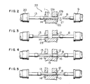
- Fig. 1 shows one example of the structure of a tablet type pelletizer to which the present invention may be applied.
- a radioactive waste powder 1 is charged into a powder hopper 5 through a powder chute 2 in a pushed manner, and, as the powder is compactly pushed, a large quantity of air contained in the powder is forced upwardly in the hopper 5 and is removed from the powder.
- the thus-pushed powder is mixed by a mixing blade 6 and a mix-supplying blade 7 which are driven by a motor 3 via a governor 4, thereby enhancing the density of powder particles.
- the radioactive waste powder 1 whose particle density is thus made high due to the mixture performed in the hopper 5 is introduced into the powder receiving cavity defined in a pelletizing section 22.
- the pelletizing section 22 has a pair of dies 12, 14 which are separately located on the right and left sides, as viewed in Fig. 2 and the above-mentioned powder receiving cavity 23 is defined between the pair of dies 14, 12.
- the die 12 on the right side constitutes a pelletizing die, and it has an inner end 12a facing the receiving cavity 23 and an outer end 12b exposed to the atmosphere, a through bore 12c being so formed as to pass from the inner end 12a to the outer end 12b.
- a hydraulic cylinder 9 is disposed on the right side of the die 12, and a second pelletizing rod or outlet rod 8 is disposed so as to be driven by the hydraulic cylinder 9 in a reciprocal manner, thereby allowing the rod 8 to be inserted into or pulled out of the through bore 12c on the side of the outer end 12b.
- Another hydraulic cylinder 20 is disposed on the left side of the die 14, and a first pelletizing rod or inlet rod 13 is adapted to be inserted into or pulled out of the through bore 12c on the side of the inner end 12a.
- the powder which is charged into the powder receiving cavity 23 is pelletized by the operation of the outlet rod 8 and the inlet rod 13 within the through bore 12c under certain pelletizing conditions (a compressive force, a compressing time and so forth), thereby obtaining a pellet 10 having the diameter and thickness which remains within a predetermined range.
- Figs. 2 through 5 show how the powder 1 introduced into the receiving cavity 23 is compressed or press-molded into the pellet 10. More specifically, Fig. 2 shows a state in which a formed or molded pellet has been released in the direction of an arrow 21. In this state, the hydraulic cylinders 9, 20 are actuated to cause the leftward movement of the inlet rod 13 and the outlet rod 8. In the state shown in Fig. 3, another powder is charged into the receiving cavity 23 for the next pelletizing operation. Subsequently, as shown in Fig. 4, the inlet rod 13 and the outlet rod 8 travels rightwardly so as to transfer the powder 1 from the inner end or inlet end 12a of the die 12 into the through bore 12c.
- the rightward movement of the outlet rod 8 is stepped at a location in which an inner end thereof is inserted by a predetermined amount into the die 12 through the outer end 12b and the rod 8 is kept stationary at this location as shown in Fig. 4.
- the inlet rod 13 further travels rightwardly as shown in Fig. 5, the powder 1 within the through bore 12c is gradually compressed and the pellet 10 is formed. Subsequently, the cycle shown in Figs. 2 to 5 is repeated, thereby enabling the continuous formation of the pellet 10.
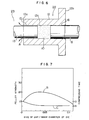
- Fig. 6 shows the essential portion of the first embodiment of the pelletizing apparatus of the present invention.
- This first embodiment is an improvement in the pelletizing section 22 of the above-described tablet type pelletizer, and a part of the improved pelletizing section 22 is shown on an enlarged scale in Fig. 6.
- the pelletizing portion 22 includes the pelletizing die 12 having one end or the inlet end 12a facing the receiving cavity 23 for a radioactive waste powder and the other end or the outlet end 12b exposed to the atmosphere.
- the through bore 12c is formed in the die 12 in such a manner as to pass from the one end 12a to the other end 12b, and the through bore 12c has a substantially identical diameter along substantially the entire length thereof.
- the first pelletizing rod i.e., the inlet rod 13 is capable of being inserted into or pulled out of the through bore 12c through the one end 12a of the die 12, while the second pelletizing rod, i.e., the outlet rod 8 is capable of being inserted into or pulled out of the through bore 12c through the other end 12b.
- the inlet rod 13 has a smaller diameter than that of the outlet rod 8.
- the size, or width of a gap 15 extending substantially in parallel with the inlet rod 13 between the rod 13 and the inside surface of the die 12 is larger than the size, or width of a gap 16 extending substantially in parallel with the outlet rod 8 between the rod 8 and the inside surface of the die 12 (the size of the gap 16 being a value obtained by subtraction of the diameter of the outlet rod 8 from that of the through bore 12c).
- the construction of the first embodiment other than the portions described above with reference to Fig. 6, is the same as that previously mentioned with reference to Figs. 1 through 5.
- the inlet rod 13 when the powder is compressed into a pellet by moving the inlet rod 13 rightwardly as viewed in Fig. 6, compressed air, as indicated by arrows A, is easily discharged through the gap 15 into the receiving cavity 23, i.e., into the interior of the pelletizer (that is, air is easily expelled out of the through bore 12c). Therefore, the time required for the compression of the powder into a pellet can be shortened as compared with the prior art. Namely, in the prior art, the inlet rod has the same diameter as the outlet rod, so that the sizes of gaps corresponding to the gaps 15, 16 are the same minute value (approximately 50 pm).
- the prior art involves disadvantage in that it is difficult to properly discharge the air compressed in the through bore 12c through the minute gaps and hence pelletizing time becomes longer.
- the first embodiment solves such disadvantage by making the size of the gap 15 larger than that of the gap 16.
- the air compressed during the pelletizing operation smoothly flows into the pelletizer through the gap 15 with a slight resistance, but never flows into the atmosphere through the gap 16. This mechanism is capable of solving the problem of environmental pollution caused by the discharge of a waste powder mixed with the compressed air into the atmosphere.
- Fig. 7 is a graph showing the relationship among the size of the gap 15, a pellet strength, and a compressing time.
- the size of the gap 15 between the inlet rod 13 and the die 12 was varied while the size of the gap 16 between the outlet rod 8 and the die 12 was set to a predetermined minimum value (approximately, 50 pm) for permitting the rod 8 to travel rightwardly and leftwardly.
- the Fig. 7 graph was obtained from experiments conducted by the inventors.
- the abscissa of the graph represents the ratio of the size of the gap 15 (that is the value obtained from the substraction of the diameter of the inlet rod 13 from the inner diameter of the die 12) to the inner diameter of the die 12 or the diameter of the through bore 12c, while the ordinates represent the pellet strength and the pelletizing or compressing time.
- the pellet strength is shown as the ratio of the strength of the pellet formed with the use of the pelletizer of the first embodiment to the strength of the pellet formed with the use of the prior art pelletizer
- the compressing time is shown as a ratio of the compressing time required with the use of the pelletizer of the first embodiment to the compressing time required with the use of the prior art pelletizer.
- the ratio values of both the pellet strength and the compressing time are shown as the values obtained under condition that each of the pellet strength and the compressing time according to the prior art is "1".
- the ratio of the size of the gap 15 to the inner diameter of the dies 12 (or the diameter of the through bore 12c) was 0.002.
- the curve B represents the pellet strength
- the curve C represents the compressing time.
- the ratio of the size of the gap 15 to the inner diameter of the die 12 is set within the numerical range between 0.005 and 0.1, and more preferably, within or near the numerical range between 0.03 and 0.04.
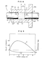
- Fig. 8 shows the second embodiment of the present invention.
- This embodiment is constructed such that the diameter of the second pelletizing rod or outlet rod 8 is made substantially identical with that of the first pelletizing rod or inlet rod 13 and the through bore 12c of the pelletizing die 12 has a taper-bore portion 12c".
- the air compressed in the through bore 12c during the pelletizing operation as shown in arrows A, is discharged through the gap 15 defined between the inlet rod 13 and the die 12 into the powder receiving cavity 23, and the air is never leaked through the gap 16 defined between the outlet rod 8 and the die 12 into the atmosphere.
- the through bore 12c has a parallel-bore portion 12c' which extends straight from the position a to the outer end 12b of the die 12 and the taper-bore portion 12c" which extends from the position a to the inner end 12a of the die 12 in such a manner that the diameter is gradually increased toward the inner end 12a.
- the position a constitutes a boundary portion or point and the taper-bore portion 12c" extends from the position a to the inner end 12a of the die 12.
- the boundary portion need not be located at the position a and, for example, it may be located at a position near the outer end 12b of the die 12. However, it is preferable that the boundary portion is located between a position b which an inner end 8a of the second pelletizing rod or outlet rod 8 takes during the pelletizing operation and the position a to which the inner end 13a of the first pelletizing rod or inlet rod 13 reaches at a final stage of the pelletizing operation. In other words, it is preferable that the boundary portion is located at a position within the area D in Fig.
- the powder since when it is located in this area the powder may be preferably compressed or press-molded between the inlet and the outlet rods 13 and 8. From this standpoint, it is particularly preferable that the boundary portion is located at the position a.
- the structures of the second embodiment other than the abovementioned structure are substantially similar to those of the first embodiment. Also in the second embodiment, compressed air is smoothly discharged through the gap 15 into the cavity 23 during the pelletizing operation, and hence the advantages substantially similar to those of the first embodiment are obtainable.
- Fig. 9 is a graph showing the relationship among the taper angle (0) of the taper-bore portion 12c" of the second embodiment, pellet strength and compressing time.
- the Fig. 9 graph was obtained from experiments conducted by the inventors.
- the abscissa of the graph represents the taper angle (e), while the ordinates represent the pellet strength and the pelletizing or compressing time.
- the pellet strength is shown as the ratio of the strength of the pellet formed with the use of the pelletizer of the second embodiment to the strength of the pellet formed with the use of the prior art pelletizer
- the compressing time is shown as the ratio of the compressing time required with the use of the pelletizer of the second embodiment to the compressing time required with the use of the prior art pelletizer.
- the ratio values of both the pellet strength and the compressing time are shown as the values obtained under condition that each of the pellet strength and the compressing time according to the prior art is "1".
- a curve E represents the pellet strength
- a curve F represents the compressing time.
- the position of the inner end 8a of the outlet rod 8 during the pelletizing operation i.e., the position b in Fig. 8 was the boundary portion.
- the part of the through bore 12c extending from the position b to the outer end 12b of the die 12 was made to be the parallel-bore portion 12c;, and the length of the portion 12c' was approximately 30mm.
- the part of the through bore 12c" extending from the position b to the inner end 12a was made to be the taper-bore portion 12c".
- the size or width of the gap 16 was approximately 50pm.
- the taper angle (6) was zero, and each of the gaps corresponding to the gaps 15 and 16 was approximately 50pm.
- Fig. 9 shows that, as the taper angle is increased, air in the through bore 12c is smoothly discharged through the gap 15 into the receiving cavity 23 and hence the pellet strength is increased, and at the same time the Fig. 9 graph shows the tendency that the uniformity of the pellet density or compactness and hence the pellet strength are lowered at the largely increased taper angle ( ⁇ ).
- ⁇ taper angle
- preferable pellet strength and compressing time were obtained at the taper angle (6) within the range of 0.01 to 5 degrees.
- Fig. 9 shows that it is most preferable that the taper angle is within or near the range of 1 to 2 degrees. In the latter taper angle, the pellet strength becomes maximum and the compressing time is shortened to about 1/2 of that of the prior art.
- the inner diameter of the die 12 was ⁇ 28
- the diameter of the outlet rod 8 was ⁇ 27.95
- a powder of boric acid soda (N a2 B 4 0 7 ) was employed and pelletized.
- compressed air produced in the course of compressing the powder was smoothly expeled through the gap 15 into the receiving cavity 23.
- the pellet strength was increased up to approximately twelve times that of the prior art, and the compressing time was reduced to about 1/2.
- the dimension 1 between the position b and the outer end 12b of the die 12 was approximately 30 mm, the part corresponding to the dimension 1 was formed into the parallel-bore portion 12c' and the part between the position b and the inner end 12a of the die 12 was formed into the taper-bore portion 12c".
- a simulated substance of a radioactive waste powder was pelletized between the rods 8 and 13 by using such pelletizer.
- compressed air produced in the course of compressing the powder was smoothly expelled through the gap 15 into the receiving cavity 23.
- compressing time was reduced to approximately 1/2.
- the powder was not scattered through the gap 16 to the atmosphere, and the strength of the obtained pellet was approximately three times that of the pellet formed by the prior art.
- the part corresponding to the dimension 1 from the outer end 12b of the die 12 to the position b was formed into the parallel-bore portion 12c' and the part from the position b to the inner end 12a of the die was formed into the taper-bore portion 12c".
- the through bore 12c has the parallel-bore portion 12c' of . substantial length.
- the parallel-bore portion 12c' has a very small length and the taper-bore portion 12c" extends from the vicinity of the outer end 12b of the die 12 to the inner end 12a of the die 12 in a manner to gradually increase the diameter toward the inner end 12a
- the parallel-bore portion 12c' extends from the outer end 12b of the die 12 to at least the position b so as to properly compress and press-mold the powder between the inlet and outlet rods 13 and 8.
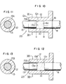
- Figs. 10, 11 show the third embodiment of the invention.
- the inlet rod 13 and the outlet rod 8 have substantially same diameter, and the diameter of the through bore 12c of the die 12 is substantially identical along substantially entire length of the bore 12c.
- a groove 15A is so formed as to extend in the longitudinal or lengthwise direction of the inside surface of the die 12.
- the groove 15A extends to the inner end 12a of the die 12 from the position a reached by the inner end 13a of the inlet rod 13 at the final stage of the pelletizing operation. It is possible to constitute such that the groove 15A extends to the inner end 12a from a position slightly rightwards from the position b of the inner end 8a of the outlet rod 8 during the pelletizing operation.
- the groove 15A extends to the inner end 12a from a given point located between the position a and the position b, and most preferably the groove 15A extends to the inner end 12a from the position a as in the illustrated embodiment.
- the structures of the third embodiment other than the structure described above are substantially similar to those of the first and second embodiments.
- the third embodiment brings about substantially similar effects to those of the first and second embodiments because of the fact that the air compressed during-the pelletizing operation is smoothly guided and expelled through the groove 15A into the cavity 23.
- Figs. 12, 13 show the fourth embodiment of the invention in which the inlet rod 13 and the outlet rod 8 have substantially the same diameter, and the inner diameter of the die 12, i.e., the diameter of the through bore 12c is substantially same along substantially entire length of the bore 12c.
- a groove 15B is so formed as to extend a predetermined length from the inner end 13a of the inlet rod 13 toward the outer end thereof along an outer periphery of the rod 13.
- the structures of the fourth embodiment other than those described above are substantially similar to those of the first to third embodiments.
- the fourth embodiment may bring about similar effects to those of the first to third embodiments since the air compressed during the pelletizing operation is smoothly expelled and discharged through the groove 15B into the receiving cavity 23.
- the present invention brings about such meritorious effect that the time required for pelletizing a radioactive waste powder may be shortened and hence it is possible to enhance efficiency of the volume-reducing treatment of the powder. Also the invention contributes to the prevention of environmental polution since during the pelletizing operation the compressed air is discharged to the interior of the pelletizing apparatus rather than to the atmosphere and hence the powder is prevented from being scattered into the atmosphere.
Landscapes
- Engineering & Computer Science (AREA)
- Mechanical Engineering (AREA)
- Environmental & Geological Engineering (AREA)
- Physics & Mathematics (AREA)
- General Engineering & Computer Science (AREA)
- High Energy & Nuclear Physics (AREA)
- Glanulating (AREA)
- Processing Of Solid Wastes (AREA)
Applications Claiming Priority (2)
| Application Number | Priority Date | Filing Date | Title |
|---|---|---|---|
| JP76485/85 | 1985-04-12 | ||
| JP60076485A JPH0636076B2 (ja) | 1985-04-12 | 1985-04-12 | 放射性廃棄物の造粒装置 |
Publications (3)
| Publication Number | Publication Date |
|---|---|
| EP0198447A2 true EP0198447A2 (de) | 1986-10-22 |
| EP0198447A3 EP0198447A3 (en) | 1988-07-20 |
| EP0198447B1 EP0198447B1 (de) | 1990-10-24 |
Family
ID=13606506
Family Applications (1)
| Application Number | Title | Priority Date | Filing Date |
|---|---|---|---|
| EP86105016A Expired EP0198447B1 (de) | 1985-04-12 | 1986-04-11 | Verfahren und Einrichtung zur Pelletisierung von radioaktiven pulverigen Abfällen |
Country Status (4)
| Country | Link |
|---|---|
| US (1) | US4755332A (de) |
| EP (1) | EP0198447B1 (de) |
| JP (1) | JPH0636076B2 (de) |
| DE (1) | DE3675061D1 (de) |
Families Citing this family (12)
| Publication number | Priority date | Publication date | Assignee | Title |
|---|---|---|---|---|
| US5001975A (en) * | 1989-12-07 | 1991-03-26 | Finden Kenneth A | Apparatus and method for the production of dehydrated high density pelletized garbage |
| US5268128A (en) * | 1990-05-25 | 1993-12-07 | Westinghouse Electric Corp. | Method and apparatus for cleaning contaminated particulate material |
| US5128068A (en) * | 1990-05-25 | 1992-07-07 | Westinghouse Electric Corp. | Method and apparatus for cleaning contaminated particulate material |
| US5358031A (en) * | 1992-06-12 | 1994-10-25 | North American Refractories Company | Interlocking checker bricks and method and apparatus for making |
| US5664492A (en) * | 1993-06-10 | 1997-09-09 | Bendzick; Ervin J. | Apparatus for compacting metal shavings |
| US5932930A (en) * | 1994-06-28 | 1999-08-03 | General Electric Company | Method for fabricating mixed oxide fuel |
| US6745679B2 (en) * | 2001-07-03 | 2004-06-08 | Ntk Corporation | Grinding sludge compacting machine |
| KR101205148B1 (ko) * | 2010-10-27 | 2012-11-26 | 현대제철 주식회사 | 스크랩 압축체 제조장치 |
| JP5548588B2 (ja) * | 2010-10-29 | 2014-07-16 | 日立粉末冶金株式会社 | 微小部品の成形金型装置 |
| JP5548587B2 (ja) * | 2010-10-29 | 2014-07-16 | 日立粉末冶金株式会社 | 微小部品の成形金型装置 |
| JP6670037B2 (ja) * | 2014-08-25 | 2020-03-18 | 太平洋セメント株式会社 | 放射性物質を含む飛灰の処理方法 |
| EP3429767A1 (de) * | 2016-03-18 | 2019-01-23 | Anaergia B.V. | Tür für eine festabfallpresse |
Family Cites Families (18)
| Publication number | Priority date | Publication date | Assignee | Title |
|---|---|---|---|---|
| US2738550A (en) * | 1951-11-30 | 1956-03-20 | British Industrial Plastics | Machine for dispensing predetermined quantities of material in loose or compressed form |
| US3524220A (en) * | 1967-11-15 | 1970-08-18 | Western Electric Co | Die set for compacting powder |
| US3606637A (en) * | 1968-04-08 | 1971-09-21 | Corning Glass Works | Apparatus for compressing materials |
| JPS537458B1 (de) * | 1971-05-15 | 1978-03-17 | ||
| DE2157465C3 (de) * | 1971-11-19 | 1975-04-24 | Werner & Pfleiderer, 7000 Stuttgart | Füllvorrichtung für eine hydraulische Blockpresse |
| BE781180A (fr) * | 1972-03-24 | 1972-07-17 | Centre Etd Energie Nucleaire | Procede de fabrication de pastilles de precision |
| SU546480A1 (ru) * | 1975-11-28 | 1977-02-15 | Пресс-форма дл изготовлени изделий из полимерных материалов | |
| FR2361221A1 (fr) * | 1976-08-13 | 1978-03-10 | British Nuclear Fuels Ltd | Presse et procede de faconnage par compression d'une poudre, notamment d'un combustible nucleaire ceramique |
| GB1556827A (en) * | 1976-08-13 | 1979-11-28 | British Nuclear Fuels Ltd | Powder compacting presses |
| US4147489A (en) * | 1977-06-22 | 1979-04-03 | British Nuclear Fuels Ltd. | Powder compacting presses |
| SE427435B (sv) * | 1980-02-13 | 1983-04-11 | Cerac Inst Sa | Anordning for kompaktering av pulver i en kompakteringskammare |
| SU903164A1 (ru) * | 1980-03-26 | 1982-02-07 | Львовский Ордена Ленина Политехнический Институт | Форма дл изготовлени контактных линз полимеризацией |
| JPS5931040B2 (ja) * | 1980-09-12 | 1984-07-30 | 株式会社日立製作所 | 放射性廃棄物の造粒装置 |
| JPS58100799A (ja) * | 1981-12-11 | 1983-06-15 | 三菱重工業株式会社 | 放射性廃棄物の処理法 |
| JPS58100800A (ja) * | 1981-12-11 | 1983-06-15 | 三菱重工業株式会社 | 放射性廃棄物の処理方法 |
| JPS58108497A (ja) * | 1981-12-22 | 1983-06-28 | 三菱重工業株式会社 | 放射性廃液の減容処理方法 |
| DE3207191A1 (de) * | 1982-02-27 | 1983-09-08 | Rheinmetall GmbH, 4000 Düsseldorf | Vorrichtung zur herstellung von presskoerpern |
| JPS5985354A (ja) * | 1982-11-09 | 1984-05-17 | Ube Ind Ltd | 金型用ガス抜き装置 |
-
1985
- 1985-04-12 JP JP60076485A patent/JPH0636076B2/ja not_active Expired - Lifetime
-
1986
- 1986-04-11 DE DE8686105016T patent/DE3675061D1/de not_active Expired - Lifetime
- 1986-04-11 US US06/850,667 patent/US4755332A/en not_active Expired - Fee Related
- 1986-04-11 EP EP86105016A patent/EP0198447B1/de not_active Expired
Also Published As
| Publication number | Publication date |
|---|---|
| EP0198447A3 (en) | 1988-07-20 |
| DE3675061D1 (de) | 1990-11-29 |
| JPH0636076B2 (ja) | 1994-05-11 |
| US4755332A (en) | 1988-07-05 |
| EP0198447B1 (de) | 1990-10-24 |
| JPS61235800A (ja) | 1986-10-21 |
Similar Documents
| Publication | Publication Date | Title |
|---|---|---|
| EP0198447B1 (de) | Verfahren und Einrichtung zur Pelletisierung von radioaktiven pulverigen Abfällen | |
| DE69127557T2 (de) | Verfahren zur Herstellung eines Permanentmagneten und Vorrichtung zur Herstellung eines Grünlings | |
| CN106653126A (zh) | 一种环形uo2燃料芯块制备方法及模具 | |
| KR20160094435A (ko) | 압출용 빌렛을 생성하기 위한 방법 및 시스템 | |
| CN101410538B (zh) | 炼钢炉尘的再循环方法 | |
| EP0262823B1 (de) | Verfahren zur Volumenreduzierung von Abfallprodukten niedriger Radioaktivität | |
| JP2003004883A (ja) | 核燃料ペレットの製造方法 | |
| JP2002536628A (ja) | (U,Pu)O2混合酸化物核燃料スクラップの乾式リサイクル方法 | |
| EP1702994A1 (de) | Verfestigter stahlherstellungsstaub, herstellungsverfahren dafür und produktionsvorrichtung dafür | |
| JPH11202073A (ja) | 核燃料ペレットの製造方法 | |
| US4575436A (en) | Production of nuclear fuel products | |
| CN208444917U (zh) | 一种废旧锂离子电池粉末煅烧筛分回收系统 | |
| JPS6479691A (en) | Manufacture of mox fuel | |
| CN220373966U (zh) | 一种固态危废物料预处理设备 | |
| Nishijima et al. | An improved process for fabricating UO2 pellets | |
| WO1996014947A1 (de) | Festschmierstoff und verfahren zu dessen herstellung | |
| RU2225047C2 (ru) | Способ сухой переработки скрапа ядерного топлива из смешанного оксида (u, pu) o2 | |
| JP2005187872A (ja) | 製鋼ダスト固形化物製造装置 | |
| EP1726666A1 (de) | Brikett als rohmaterial für die stahlherstellung und herstellungsverfahren dafür | |
| JPS62165200A (ja) | タブレツテイング型造粒機の制御方式 | |
| JPH0365227B2 (de) | ||
| DE10058934A1 (de) | Tablettenpresse | |
| JPH0829590A (ja) | 核燃料成形体の成形方法およびその成形装置 | |
| KR100334328B1 (ko) | 중금속 함유 비산재 처리방법 및 이 처리방법으로 제조된고형물을 사용하는 복토재 | |
| JPH0157616B2 (de) |
Legal Events
| Date | Code | Title | Description |
|---|---|---|---|
| PUAI | Public reference made under article 153(3) epc to a published international application that has entered the european phase |
Free format text: ORIGINAL CODE: 0009012 |
|
| AK | Designated contracting states |
Kind code of ref document: A2 Designated state(s): DE FR GB SE |
|
| PUAL | Search report despatched |
Free format text: ORIGINAL CODE: 0009013 |
|
| AK | Designated contracting states |
Kind code of ref document: A3 Designated state(s): DE FR GB SE |
|
| 17P | Request for examination filed |
Effective date: 19880722 |
|
| 17Q | First examination report despatched |
Effective date: 19900220 |
|
| RBV | Designated contracting states (corrected) |
Designated state(s): DE FR GB |
|
| GRAA | (expected) grant |
Free format text: ORIGINAL CODE: 0009210 |
|
| AK | Designated contracting states |
Kind code of ref document: B1 Designated state(s): DE FR GB |
|
| REF | Corresponds to: |
Ref document number: 3675061 Country of ref document: DE Date of ref document: 19901129 |
|
| ET | Fr: translation filed | ||
| PLBE | No opposition filed within time limit |
Free format text: ORIGINAL CODE: 0009261 |
|
| STAA | Information on the status of an ep patent application or granted ep patent |
Free format text: STATUS: NO OPPOSITION FILED WITHIN TIME LIMIT |
|
| 26N | No opposition filed | ||
| PGFP | Annual fee paid to national office [announced via postgrant information from national office to epo] |
Ref country code: FR Payment date: 19940217 Year of fee payment: 9 |
|
| PGFP | Annual fee paid to national office [announced via postgrant information from national office to epo] |
Ref country code: GB Payment date: 19940405 Year of fee payment: 9 |
|
| PGFP | Annual fee paid to national office [announced via postgrant information from national office to epo] |
Ref country code: DE Payment date: 19940630 Year of fee payment: 9 |
|
| PG25 | Lapsed in a contracting state [announced via postgrant information from national office to epo] |
Ref country code: GB Effective date: 19950411 |
|
| GBPC | Gb: european patent ceased through non-payment of renewal fee |
Effective date: 19950411 |
|
| PG25 | Lapsed in a contracting state [announced via postgrant information from national office to epo] |
Ref country code: FR Effective date: 19951229 |
|
| PG25 | Lapsed in a contracting state [announced via postgrant information from national office to epo] |
Ref country code: DE Effective date: 19960103 |
|
| REG | Reference to a national code |
Ref country code: FR Ref legal event code: ST |