EP0197652A1 - Ensemble échangeur de chaleur utilisant une plaque adaptable pour la réalisation d'un écoulement avec passage soit simple, soit double - Google Patents
Ensemble échangeur de chaleur utilisant une plaque adaptable pour la réalisation d'un écoulement avec passage soit simple, soit double Download PDFInfo
- Publication number
- EP0197652A1 EP0197652A1 EP86301569A EP86301569A EP0197652A1 EP 0197652 A1 EP0197652 A1 EP 0197652A1 EP 86301569 A EP86301569 A EP 86301569A EP 86301569 A EP86301569 A EP 86301569A EP 0197652 A1 EP0197652 A1 EP 0197652A1
- Authority
- EP
- European Patent Office
- Prior art keywords
- plate
- portions
- header
- plate member
- plate members
- Prior art date
- Legal status (The legal status is an assumption and is not a legal conclusion. Google has not performed a legal analysis and makes no representation as to the accuracy of the status listed.)
- Granted
Links
Images

Classifications
-
- F—MECHANICAL ENGINEERING; LIGHTING; HEATING; WEAPONS; BLASTING
- F28—HEAT EXCHANGE IN GENERAL
- F28D—HEAT-EXCHANGE APPARATUS, NOT PROVIDED FOR IN ANOTHER SUBCLASS, IN WHICH THE HEAT-EXCHANGE MEDIA DO NOT COME INTO DIRECT CONTACT
- F28D1/00—Heat-exchange apparatus having stationary conduit assemblies for one heat-exchange medium only, the media being in contact with different sides of the conduit wall, in which the other heat-exchange medium is a large body of fluid, e.g. domestic or motor car radiators
- F28D1/02—Heat-exchange apparatus having stationary conduit assemblies for one heat-exchange medium only, the media being in contact with different sides of the conduit wall, in which the other heat-exchange medium is a large body of fluid, e.g. domestic or motor car radiators with heat-exchange conduits immersed in the body of fluid
- F28D1/03—Heat-exchange apparatus having stationary conduit assemblies for one heat-exchange medium only, the media being in contact with different sides of the conduit wall, in which the other heat-exchange medium is a large body of fluid, e.g. domestic or motor car radiators with heat-exchange conduits immersed in the body of fluid with plate-like or laminated conduits
- F28D1/0308—Heat-exchange apparatus having stationary conduit assemblies for one heat-exchange medium only, the media being in contact with different sides of the conduit wall, in which the other heat-exchange medium is a large body of fluid, e.g. domestic or motor car radiators with heat-exchange conduits immersed in the body of fluid with plate-like or laminated conduits the conduits being formed by paired plates touching each other
- F28D1/0325—Heat-exchange apparatus having stationary conduit assemblies for one heat-exchange medium only, the media being in contact with different sides of the conduit wall, in which the other heat-exchange medium is a large body of fluid, e.g. domestic or motor car radiators with heat-exchange conduits immersed in the body of fluid with plate-like or laminated conduits the conduits being formed by paired plates touching each other the plates having lateral openings therein for circulation of the heat-exchange medium from one conduit to another
- F28D1/0333—Heat-exchange apparatus having stationary conduit assemblies for one heat-exchange medium only, the media being in contact with different sides of the conduit wall, in which the other heat-exchange medium is a large body of fluid, e.g. domestic or motor car radiators with heat-exchange conduits immersed in the body of fluid with plate-like or laminated conduits the conduits being formed by paired plates touching each other the plates having lateral openings therein for circulation of the heat-exchange medium from one conduit to another the plates having integrated connecting members
-
- Y—GENERAL TAGGING OF NEW TECHNOLOGICAL DEVELOPMENTS; GENERAL TAGGING OF CROSS-SECTIONAL TECHNOLOGIES SPANNING OVER SEVERAL SECTIONS OF THE IPC; TECHNICAL SUBJECTS COVERED BY FORMER USPC CROSS-REFERENCE ART COLLECTIONS [XRACs] AND DIGESTS
- Y10—TECHNICAL SUBJECTS COVERED BY FORMER USPC
- Y10T—TECHNICAL SUBJECTS COVERED BY FORMER US CLASSIFICATION
- Y10T29/00—Metal working
- Y10T29/49—Method of mechanical manufacture
- Y10T29/4935—Heat exchanger or boiler making
- Y10T29/49366—Sheet joined to sheet
Definitions
- the present invention relates to a heat exchanger core construction adaptable for use in charged air cooler assemblies for turbo-charged internal combustion engines and, more particularly, to a heat exchanger core construction of the plate and fin type wherein a plurality of identical elongated plate members are joined together in a stackable mating arrangement such that either a single-pass or a double-pass system is formed between each respective pair of plate members so joined depending upon the particular orientation thereof. Wnen two of the present core plate members are joined together in face-to-face relationship, a neat exchanger element is formed naving a central flow region therebetween.
- the mated core plate members form a double-pass flow arrangement therebetween whereas a single-pass flow arrangement may be achieved by simple reorientation of the mating core plate members.
- Tne provision for achieving single or double pass fluid flow arrangements by utilizing a universal core plate member significally reduces the tooling requirements for producing a family of heat exchanger constructions as needed for a wide variety of applications.
- a wide variety of heat exchanger core constructions nave been designed and manufactured for use as heat exchangers in a wide variety of applications such as for use in turoo-cnarged internal combustion engines and other applications.
- the use of heat exchangers in an extremely wide range of industrial and commercial applications coupled with tne nignly desirable goals of energy conservation and fuel economy in all neat and energy related devices have resulted in a rapidly growing worldwide demand for tne design of efficient, reliable, and economical heat exchanger equipment.
- Typical of such heat exchanger core constructions is tne plate and fin type construction wherein heat transfer is effected between one fluid medium flowing through the central flow region formed by a pair of mated plate members and a second fluid medium flowing externally over the central flow region through flow passageways formed by and between fin elements that are interposed between adjacent plate assemblies to increase the effective neat transfer therebetween.
- a transfer of heat occurs directly between the fluid medium flowing within the central flow region and the external fluid medium flowing over and around the plate members.
- a typical plate member generally includes a header portion at each opposite end thereof.
- a pair of plate members are mated together to form a plate assembly and when stacked one upon the other, the header portions associated with each plate assembly mate with the header portions of adjacent plate assemblies and form inlet or outlet headers adaptable to receive and discharge a fluid medium therethrough.
- the construction of each plate member limits the use thereof to a specific type of fluid flow through the core construction.
- Donaldson U.S. Patent No. 3,207,216 discloses a core plate construction wherein the plate members are constructed such that when the plate members are mated together, a single-pass flow arrangement is produced. Slaasted et al U. S. Patent No.
- each plate member includes intermediate portions such that, when mated together, they produce a double-pass flow arrangement.
- DeGroote et al U. S. Patent No. 3,907,032 discloses a heat exchanger construction wherein a plurality of tubes and header portions produce a multi-pass flow arrangement.
- Each of these constructions is limited to the specific flow arrangement described therein and to change any one of the specific types of flow arrangements disclosed respectively therein would require complete restructuring of the core plate members to achieve the newly desired pass flow arrangement.
- a user of a variety of fluid flow arrangements must have a variety of plate member constructions available and the manufacturers of such plate members must produce and provide this variety of plate members to meet the specific needs of the user.
- Manufacture and use of the prior art core plate devices are tnerefore not only expensive but likewise inconvenient.
- the present heat exchanger core construction overcomes many of tne disadvantages and shortcomings associated with prior art plate type heat exchanger constructions, and teaches the construction and operation of a heat exchanger construction tnat utilizes a plurality of identical plate members which may be stackably arranged in various mating positions to produce either a single-pass or a double-pass cross-flow system.
- the construction of the universal core plate member utilized in the present invention substantially reduces the costly tooling requirements necessary to manufacture a wide variety of plate member constructions and provides the user with the ability to use the same core plate member in both single-pass and double-pass flow applications. Since users of both single-pass and double-pass core assemblies will no longer need to purchase and stock multiple core plate constructions to achieve the desired pass flow system, use of the present core plate members will reduce user cost and inventory.
- the present heat exchanger core construction comprises individual core plate members having a dished or header portion formed integrally therewith at each opposite end thereof.
- Each header portion preferably includes at least a pair of openings adaptable for registration with corresponding openings on an adjacent plate member to fluidly interconnect the adjacent header portions such that one fluid medium may pass therethrough and circulate through the central flow region formed between mating plate members as will be hereinafter explained.
- the openings located in the dished or header portions of each plate member are preferably symmetrically arranged at each end thereof and the openings associated with the header portion located at one end of the plate member have corresponding complementary openings associated with the header portion located at the opposite end thereof.
- circumferential flange members surround at least one of the openings in each header portion to aid in positioning and stacking the respective pairs of mated plate members.
- Each core plate member also includes a raised partitioning or pass rib preferably formed integral therewith and positioned between the pair of openings associated with only one of the header portions. This raised pass rib is important to the present invention because it is the positioning of the respective pass ribs associated with each pair of mated plate members relative to one another which determines the particular flow arrangement of the core assembly embodying the present plate members.
- Each core plate member additionally includes spaced flange tabs arranged asymmetrically along the periphery thereof to facilitate the positioning of one core plate member relative to another when assembling the same. These flange tabs are positioned so as to be adaptable to register with and engage an untabbed edge portion of a complementary plate member when placed in mating relationship therewith to form either of the flow arrangements hereinafter described.
- one header portion of the formed heat exchanger element is separated into two distinct sections thereby providing separate means for coolant fluid to enter and exit the central flow region formed tnerebetween.
- each pair of core plate members so joined is effectively separated into two coolant passes tnereby achieving a double-pass flow arrangement within each heat exchanger element or plate assembly.
- a single-pass flow arrangement may likewise be produced by joining together two core plate members in face-to-face relationship with each other such that the raised pass ribs associated with the one header portion of the respective plate members are located at opposite ends thereof.
- This arrangement allows a coolant fluid to enter one header portion and flow freely within the single flow region formed between the mated core plate members and thereafter exit through the header portion located at the opposite end thereof.
- Use of the present core plate members provides an improved means for providing separation of adjacent flow passageways within the central flow region formed between the respective pairs of mated plate members and this makes the present plate members particularly suitable for, but not limited to, use in charged air cooler assemblies for turbo charged engines.
- a typical core assembly embodying the present core plate members is produced by stacking the mated plate assemblies one upon the other and interposing heat transfer fin elements between adjacent plate assemblies, the fin elements extending throughout the full interior area therebetween forming a second series of relatively small fluid flow passageways therewithin for receiving and transporting a second fluid medium, such as air, therethrough.
- the second series of fluid passageways extend in a direction perpendicular to the Central flow region formed between each pair of mated plate members thereby achieving a cross-flow pattern of fluid distribution through the heat exchanger core structure.
- Another object is to provide a single core plate member which may be utilized to form either a single-pass or a double-pass flow arrangement through the central flow region formed between mating core plate members.
- Another object is to teach the construction of a core plate member which will substantially reduce the tooling requirements for producing a family of heat exchanger core assemblies.
- Another object is to provide an improved heat exchanger core contruction utilizing core plate members that are easily stacked and positioned without the use of jigs or other supporting apparatus.
- Another object is to provide an improved heat exchanger core construction having improved strength and stability.
- Another object is to provide an improved heat exchanger core construction including means associated with the respective core plate members for providing a solid bond therebetween when said plate members are stackably arranged one upon the other.
- Another object is to provide an improved means for providing separation of adjacent flow passageways within the central flow region formed between respective pairs of core plate members.
- Another object is to provide an improved heat exchanger core construction that is structurally and operationally relatively simple and inexpensive.
- Another object is to provide a core construction which can be economically produced for commercial use.
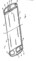
- numoer 10 in Figs. 1 and 2 refers to a core plate member constructed according to the teachings of the present invention.
- Each plate member 10 is substantially flat in shape and each includes dished or header portions 12 and 14 located respectively at each opposite end thereof.
- the header portions 12 and 14 are preferably integrally formed with each plate member 10 although any suitable means for attaching the header portions to the plate number 10 may be utilized.
- Each header portion 12 includes a pair of spaced openings 16 and 18 and each header portion 14 includes a pair of spaced openings 20 and 22 as shown in Figs. 1 and 2.
- the header openings 16, 18, 20 and 22 are adaptable for registration with corresponding openings on an adjacent plate member 10 to fluidly interconnect adjacent header portions such that one fluid medium may pass therethrough and circulate through the central flow region formed between mating plate members as will be explained.
- Tne openings located in tne dished or header portions 12 and 14 of each plate member 10 are symmetrically arranged at each end thereof and the openings associated with the header portion 12 nave corresponding complementary openings associated with the header portion 14.
- the respective header portion3 form the header tanks of the present core constructions.
- Circumferential flange members 24 and 26 are likewise utilized to further secure the connection between respective header portions as will be nereinafter explained.
- Each core plate member 10 also includes a raised pass or partitioning rib 28 perferably intergrally formed with only one of the header portions associated with each plate member such as the header portion 12 shown in Figs. 1 and 2.
- the pass rib 28 is positioned between the pair of openings 16 and 18 and extends from one end 30 of the header portion 12 to the other end 32 thereof.
- a continuous raised peripheral edge portion 34 (Fig. 2) extends around each of the plate members 10 on one surface thereof and the partitioning or pass rib 28 associated with each header portion 12 extends from and lies coplanar with the peripheral edge portion 34.
- Each core plate member additionally includes spaced flange tabs 36 and 38 arranged and positioned asymmetrically along the peripheral edge 34 to facilitate the positioning of one plate member 10 relative to another when assembling the same.
- the flange tabs 36 and 38 are positioned and located as shown in Figs. 1 and 2 so as to be adaptable to register with and engage complementary untabbed edge portions such as the untabbed portions 39 and 40 of a complementary plate member 10 when placed in face-to-face mating relationship therewitn. It is important to note that the complementary untabbed edge portions associated with the present plate member 10 are substantially equal in length to the corresponding flange tabs and the untabbed portions are positioned substantially directly opposite the position of tne flange tabs as shown in Figs. 1 and 2.
- the flange tabs 36 and 38 are arranged along the periphery of plate member 10 such that the flange tab 36 extends from a position adjacent the partitioning rib 28 to an intermediate position along the peripheral side edge 34 such that the length thereof is equal to approximately one quarter of the distance around the entire periphery thereof.
- the flange tab 38 is spaced from the flange tab 36 a distance equal to the length of the flange tab 36 and extends similarly from a position adjacent the space between the pair of openings 20 and 22 associated with the header portion 14 to an intermediate position along the opposite peripheral side edge 34 such that the length thereof is likewise equal to approximately one quarter of the distance around the entire periphery of plate member 10.
- This specific arrangement of the flange tabs 36 and 38 not only facilitates the positioning of the core plate members 10 during assembly but also assists in securing a solid bond between the respective plate members during the brazing operation.
- the bonding material for example, a brazing alloy, can flow readily into the juncture between the peripheral flange tabs 36 and 38 of one plate member 10 and the untabbed edged portions 39 and 40 associated with the mating plate member 10 to firmly seal the same and provide an effective joinder therebetween.
- each flange tab on one plate member 10 is registrable and engageable witn a corresponding untabbed portion on a complementary plate member 10 when said plate members are placed in face-to-face mating relationship with one another.
- the specific arrangement of tabbed and untabbed portions hereinbefore described and shown in Figs. 1 and 2 is preferred because plate members utilizing such an arrangement have a minimum of continuous tabbed and untabbed portions associated therewith and are therefore simpler and less expensive to manufacture as compared to plate members having a different arrangement and a greater plurality of such tabbed and untabbed portions.
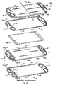
- a heat exchanger core assembly 42 is formed by joining together a plurality of plate members 10. More specifically, when two of the present plate members 10 are joined together in face-to-face relationship with the flange tabs 36 and 38 of one plate member engaging the untabbed portions 39 and 40 of a complementary plate member as previously explained, a heat exchanger element or plate assembly 43 is formed having a central flow region 44 extending substantially the entire width between the joined plate members. To provide a further secured connection between adjacent pairs of mated plate members 10, one opening in each of the header portions 12 and 14 such as the openings 16 and 20 is provided with a circumferential flange member surrounding the same such as tne flange members 24 and 26 respectivey as shown in Figs. 1 and 2.
- the flange members 24 and 26 are receivable and insertable within the complementary unflanged header openings 18 and 22 in an adjacent pair of mated plate members or plate assemblies 43 to furtner aid in positioning and stacking the plate assemblies 43 without the use of jigs or other supporting hardware. This likewise improves the strength and stability of the entire core unit 42 and also helps to provide a solid bond between the respective pairs of plate members or assemblies 43 during the brazing operation.
- the circumferential flange members 24 and 26 also serve to fluidly interconnect the respective header openings between adjacent plate assemblies.
- a typical heat exchanger core assembly 42 embodying the present invention comprises a plurality of the plate assemblies 43 stacked one upon the other with serpentine heat transfer fins 46 interposed between adjacent plate assemblies.
- the serpentine fin elements 46 extend throughout the full interior area 48 formed between the stacked plate assemblies 43 and form a second series of relatively small fluid flow passageways 50 therewithin for receiving and transporting a second fluid medium, such as air, therethrough.
- a second fluid medium such as air
- the header portions 12 and 14 associated with each pair of mated plate members 10 mate with adjacent plate assemblies 43 and form common inlet and outlet headers 52 and 54 respectively adaptable to receive and discharge a fluid medium therethrough as previously explained.
- the serpentine fin elements 46 are positioned such that the second series of fluid flow passageways 50 extend in a direction perpendicular to the central flow region 44 formed between each pair of mated plate members thereby achieving a cross-flow pattern of fluid distribution through the heat exchanger core structure 42.
- a single-pass or a double-pass flow system within each-plate assembly may be achieved.
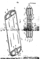
- a mated plate assembly 60 (Fig. 5) is formed wherein the raised partitioning or pass ribs 28 of the respective header portions 12 are positioned and arranged in abutting relationship with each other such that the assembled header portion 62 formed thereby at one end portion thereof is separated into two distinct flow sections 64 and 66 as shown in Fig. 5.
- FIG. 5 is a cross-sectional view of the plate assembly 60 taken through the plane 5-5 of Fig. 4 showing one method of joining complementary plate members together wherein each of the flange tabs 36 and 38 is folded over or crimped around the respective untabbed portions 39 and 40.
- This method of mating a pair of complementary plate members provides additional strength and stability to the plate assemblies 43.
- the flow sections 64 and 66 provide a means for coolant fluid to enter and exit the central flow region formed between the mated plate members 10.
- each plate assembly 60 so assembled is effectively separated into two coolant passes 70 and 72 (Fig. 4). This means that one fluid medium may enter one opening associated with the separated header portion 62 and flow the full lengtn of the plate assembly 60 along one of the passageways 70 or 72 formed therewithin.
- a double-pass cross-flow core assembly is formed by stacking a plurality of the douole-pass plate assemblies 60 one upon the other and interposing heat transfer fin elements such as the fin elements 46 between adjacent plate assemblies as previously discussed with respect to the core assembly 42 shown in Fig. 3.
- An important aspect of the construction of the present plate members 10 is to provide a plate design which can also be utilized in the assembly of a single-pass core unit.
- a double-pass plate assembly is achieved by rotating one of the plate members 10 forming each pair of mated plate members 180° about its longitudinal axis as shown in Figs. 4 and 5.
- a single-pass flow arrangement can be achieved by rotating one of said pair of plate members 10 180° about its transverse axis A-A shown in Figs. 1 and 6 and thereafter joining said plate members 10 in face-to-face relationship with each otner as previously explained to form a mated plate assembly such as the plate assemblies 74 shown in Figs. 6 and 7.
- a space 76 exists within both header portions formed thereby sucn as the header portion 80 shown in Fig 7 for allowing a fluid medium to communicate from one side 82 to the otner side 84 therewitnin and neither header portion is Separated as hereinbefore described.
- Fig. 7 is a cross-sectional view of one of the plate assemblies 74 taken througn the plane 7-7 of Fig. 6.
- a single pass cross-flow core assembly can be achieved by simply stacking a plurality of single-pass plate assemblies 74 in a manner substantially similar to the forming of the double-pass cross-flow core assembly previously described with respect to Figs. 4 and 5 and interposing heat transfer fin elements such as the fin elements 88 (Fig. 6) between the adjacent plate assemblies 74.
- each of the flange tabs 36 and 38 of one plate member 10 still register with and engage respective untabbed portions 39 and 40 of the complementary plate member 10.
- each of the flange tabs 36 and 38 can be folded over or crimped around the respective untabbed portions 39 and 40 to further provide additional strength and stability to the plate assemblies 74. This is best shown in Fig. 7.
- the tabbed and untabbed portions associated respectively therewith will always register witn and engage one another to from the continuous sidewall such as the sidewall 41 (Fig. 3) between the mated plate members and to effect joinder therebetween.
- the openings in the respective header portions of the plate assemblies formed thereby will always lie in registration with the corresponding openings on an adjacent plate assembly to fluidly interconnect said pair of plate members and any plurality thereof.
- all of the structural members comprising the two core embodiments which utilize the present plate members 10 are formed of a suitable heat conducting metal such as aluminum, copper and/or copper clad, or stainless steel, and all sucn members may be interconnected by any suitable bonding means such as by brazing to form the unitized core structure.
- suitable manifolding at one or both ends of the core structure is also provided for directing the two fluid media through their respective flow passageways formed within the core assembly in heat exchange relationship with each other to effect heat transfer therebetween.
- the overall size and shape of the individual plate members 10 may be conveniently fashioned into a variety of sizes and configurations, for example. rectangular, square, oval, circular, hexagonal, or other configurations, so as to be compatible with the size and shape of the manifold housing into which it may be mounted or to conform with any other space limitations without impairing the teachings and practice of the present plate construction.
- Use of the present plate members 10 provides an improved means for providing separation of adjacent flow passageways within the central flow region formed between the respective pairs of mated plate members and although the present plate members are particularly suitable for use in charged air cooler assemblies for turbo-charged engines, they may likewise be effectively utilized in a wide variety of heat exchanger applications.
Landscapes
- Engineering & Computer Science (AREA)
- Physics & Mathematics (AREA)
- Thermal Sciences (AREA)
- Mechanical Engineering (AREA)
- General Engineering & Computer Science (AREA)
- Heat-Exchange Devices With Radiators And Conduit Assemblies (AREA)
Applications Claiming Priority (2)
| Application Number | Priority Date | Filing Date | Title |
|---|---|---|---|
| US06/708,827 US4592414A (en) | 1985-03-06 | 1985-03-06 | Heat exchanger core construction utilizing a plate member adaptable for producing either a single or double pass flow arrangement |
| US708827 | 1985-03-06 |
Publications (2)
| Publication Number | Publication Date |
|---|---|
| EP0197652A1 true EP0197652A1 (fr) | 1986-10-15 |
| EP0197652B1 EP0197652B1 (fr) | 1989-07-05 |
Family
ID=24847333
Family Applications (1)
| Application Number | Title | Priority Date | Filing Date |
|---|---|---|---|
| EP86301569A Expired EP0197652B1 (fr) | 1985-03-06 | 1986-03-05 | Ensemble échangeur de chaleur utilisant une plaque adaptable pour la réalisation d'un écoulement avec passage soit simple, soit double |
Country Status (6)
| Country | Link |
|---|---|
| US (1) | US4592414A (fr) |
| EP (1) | EP0197652B1 (fr) |
| JP (1) | JPS61259086A (fr) |
| BR (1) | BR8600975A (fr) |
| DE (1) | DE3664235D1 (fr) |
| IN (1) | IN167046B (fr) |
Cited By (2)
| Publication number | Priority date | Publication date | Assignee | Title |
|---|---|---|---|---|
| US6834943B2 (en) | 1997-08-05 | 2004-12-28 | Canon Kabushiki Kaisha | Liquid discharge head, a substrate for use of such head and a method of manufacture therefor |
| DE102005002063A1 (de) * | 2005-01-14 | 2006-07-20 | Behr Gmbh & Co. Kg | Stapelscheiben -Wärmetauscher |
Families Citing this family (40)
| Publication number | Priority date | Publication date | Assignee | Title |
|---|---|---|---|---|
| SE462059B (sv) * | 1986-12-19 | 1990-04-30 | Blackstone Sweden | Vaermevaexlare med platta roer, vilka roer bildas av tvaa halvor med oeverlappande flaensar |
| DE3852552T2 (de) * | 1987-11-17 | 1995-05-24 | Ebara Shinwa Ltd | Wärmetauscher für einen Kühlturm. |
| US4829780A (en) | 1988-01-28 | 1989-05-16 | Modine Manufacturing Company | Evaporator with improved condensate collection |
| US4872578A (en) * | 1988-06-20 | 1989-10-10 | Itt Standard Of Itt Corporation | Plate type heat exchanger |
| US4860421A (en) * | 1989-02-23 | 1989-08-29 | General Motors Corporation | Method for assembling plate type heat exchangers |
| CA1313182C (fr) * | 1989-02-24 | 1993-01-26 | Allan K. So | Echangeur de chaleur pour reservoir d'huile |
| US5369883A (en) * | 1989-02-24 | 1994-12-06 | Long Manufacturing Ltd. | Method for making an in tank oil cooler |
| US5538077A (en) * | 1989-02-24 | 1996-07-23 | Long Manufacturing Ltd. | In tank oil cooler |
| US4901414A (en) * | 1989-03-27 | 1990-02-20 | General Motors Corporation | Method for assembling pairs of heat exchanger plates |
| JPH03121360U (fr) * | 1990-03-16 | 1991-12-12 | ||
| JPH04177094A (ja) * | 1990-11-13 | 1992-06-24 | Sanden Corp | 積層型熱交換器 |
| US5138764A (en) * | 1991-04-18 | 1992-08-18 | General Motors Corporation | Method for assembling heat exchanger plate pairs by snap fit |
| IT226255Z2 (it) * | 1992-02-18 | 1997-06-02 | Miralfin Srl | Struttura di radiatore particolarmente per il riscaldamento di locali |
| AU668403B2 (en) * | 1992-08-31 | 1996-05-02 | Mitsubishi Jukogyo Kabushiki Kaisha | Stacked heat exchanger |
| DE4307503C2 (de) * | 1993-03-10 | 1995-01-19 | Mtu Friedrichshafen Gmbh | Wärmetauscher, insbesondere Ladeluftkühler einer Brennkraftmaschine |
| DE4307504C1 (de) * | 1993-03-10 | 1994-09-22 | Mtu Friedrichshafen Gmbh | Wärmetauscher, insbesondere Ladeluftkühler einer Brennkraftmaschine |
| US5529120A (en) * | 1994-02-01 | 1996-06-25 | Hubbell Incorporated | Heat exchanger for electrical cabinet or the like |
| JP3814917B2 (ja) * | 1997-02-26 | 2006-08-30 | 株式会社デンソー | 積層型蒸発器 |
| SE509104C2 (sv) * | 1997-04-22 | 1998-12-07 | Volvo Lastvagnar Ab | Metod vid tillverkning av en plattvärmeväxlare |
| DE19723878B4 (de) * | 1997-06-06 | 2007-10-25 | Behr Gmbh & Co. Kg | Wärmeübertrager |
| CA2260890A1 (fr) * | 1999-02-05 | 2000-08-05 | Long Manufacturing Ltd. | Echangeurs de chaleur fermes |
| JP4056663B2 (ja) * | 1999-10-01 | 2008-03-05 | 昭和電工株式会社 | 積層型熱交換器 |
| JP3479477B2 (ja) * | 1999-12-16 | 2003-12-15 | Smc株式会社 | 温調装置用熱交換装置 |
| KR20020061757A (ko) * | 2001-01-17 | 2002-07-25 | 한국델파이주식회사 | 자동차용 증발기의 튜브 플레이트 |
| DE10120483A1 (de) * | 2001-04-25 | 2002-10-31 | Modine Mfg Co | Anordnung zur Kühlung |
| US7188417B2 (en) * | 2002-06-28 | 2007-03-13 | United Technologies Corporation | Advanced L-channel welded nozzle design |
| KR100687637B1 (ko) * | 2002-07-11 | 2007-02-27 | 한라공조주식회사 | 열교환기 |
| FR2846733B1 (fr) * | 2002-10-31 | 2006-09-15 | Valeo Thermique Moteur Sa | Condenseur, notamment pour un circuit de cimatisation de vehicule automobile, et circuit comprenant ce condenseur |
| US7069981B2 (en) * | 2002-11-08 | 2006-07-04 | Modine Manufacturing Company | Heat exchanger |
| SE524307C2 (sv) * | 2003-07-24 | 2004-07-27 | Swep Int Ab | Förfarande för framställning av en plattvärmeväxlare |
| JP2005055074A (ja) * | 2003-08-04 | 2005-03-03 | Calsonic Kansei Corp | 熱交換器 |
| SE530574C2 (sv) * | 2006-11-20 | 2008-07-08 | Alfa Laval Corp Ab | Plattvärmeväxlare |
| FR2929390B1 (fr) * | 2008-03-26 | 2014-10-10 | Valeo Systemes Thermiques | Plaque d'echangeur de chaleur |
| EP2669027B8 (fr) * | 2012-06-01 | 2016-03-16 | Kelvion PHE GmbH | Procédé et outil de presse pour la fabrication d'un échangeur thermique à plaques |
| JP6329756B2 (ja) * | 2013-11-26 | 2018-05-23 | 株式会社マーレ フィルターシステムズ | オイルクーラ |
| KR101586646B1 (ko) * | 2014-03-17 | 2016-01-19 | 주식회사 경동나비엔 | 온수난방 잠열열교환기 및 이를 포함하는 콘덴싱 가스보일러 |
| EP3183526A1 (fr) * | 2014-10-01 | 2017-06-28 | Mitsubishi Heavy Industries Compressor Corporation | Échangeur de chaleur de type stratifié à plaques |
| US20170245394A1 (en) * | 2016-02-18 | 2017-08-24 | Ironside Engineering Inc. | High Efficiency Heat Dissipation Methods And Systems For Electronic Circuits And Systems |
| WO2018147471A1 (fr) * | 2017-02-13 | 2018-08-16 | 株式会社ティラド | Échangeur de chaleur à douille de roulement |
| CN206542684U (zh) * | 2017-03-10 | 2017-10-03 | 讯凯国际股份有限公司 | 可连续接合的液冷换热片 |
Citations (10)
| Publication number | Priority date | Publication date | Assignee | Title |
|---|---|---|---|---|
| GB130104A (en) * | 1917-04-03 | 1919-07-31 | Charles Cuau | Improvements in or relating to Radiators for Internal Combustion Engines. |
| GB487840A (en) * | 1936-12-24 | 1938-06-24 | Ahlborn E Ag | Improvements in and relating to plate heat exchangers for fluids |
| GB655076A (en) * | 1947-02-24 | 1951-07-11 | Cherry Burrell Corp | Improvements in or relating to gaskets for plate apparatus in particular plate type heat exchangers or filter presses |
| GB1131124A (en) * | 1966-02-10 | 1968-10-23 | Serck Radiators Ltd | Plate-type heat exchangers |
| FR2010517A1 (en) * | 1968-06-06 | 1970-02-20 | Delaney Gallay Ltd | Heat exchanger |
| FR2194933A1 (fr) * | 1972-07-28 | 1974-03-01 | Volkswagenwerk Ag | |
| US3893509A (en) * | 1974-04-08 | 1975-07-08 | Garrett Corp | Lap joint tube plate heat exchanger |
| US3907032A (en) * | 1971-04-27 | 1975-09-23 | United Aircraft Prod | Tube and fin heat exchanger |
| DE2521279A1 (de) * | 1974-05-24 | 1975-12-04 | Borg Warner | Waermetauscherplatte |
| FR2280871A1 (fr) * | 1974-08-01 | 1976-02-27 | Chausson Usines Sa | Echangeur de chaleur a sous-ensembles empiles |
Family Cites Families (11)
| Publication number | Priority date | Publication date | Assignee | Title |
|---|---|---|---|---|
| US1029099A (en) * | 1910-04-13 | 1912-06-11 | Emil Behringer | Manufacture of radiator-tubes. |
| US1158576A (en) * | 1914-04-01 | 1915-11-02 | Pressed Metal Radiator Company | Method of making sheet-metal radiators. |
| US2538043A (en) * | 1946-02-21 | 1951-01-16 | James A S Roy | Support |
| GB739350A (en) * | 1953-01-23 | 1955-10-26 | Ford Motor Co | Improvements in or relating to beam members |
| US2814159A (en) * | 1955-04-11 | 1957-11-26 | Spectoyculars Inc | Building unit and assembly for toys and the like |
| US4470455A (en) * | 1978-06-19 | 1984-09-11 | General Motors Corporation | Plate type heat exchanger tube pass |
| SE412284B (sv) * | 1978-07-10 | 1980-02-25 | Alfa Laval Ab | Vermevexlare innefattande ett flertal i ett stativ inspenda, i huvudsak rektangulera plattor |
| US4407359A (en) * | 1980-07-25 | 1983-10-04 | Commissariat A L'energie Atomique | Plate heat exchanger |
| US4298061A (en) * | 1980-08-15 | 1981-11-03 | The Singer Company | Heat exchanger with crimped flange seam |
| US4308915A (en) * | 1980-10-27 | 1982-01-05 | Sanders Nicholas A | Thin sheet heat exchanger |
| US4350201A (en) * | 1981-01-12 | 1982-09-21 | United Aircraft Products, Inc. | Self fixturing heat exchanger |
-
1985
- 1985-03-06 US US06/708,827 patent/US4592414A/en not_active Expired - Fee Related
-
1986
- 1986-03-04 IN IN147/MAS/86A patent/IN167046B/en unknown
- 1986-03-05 EP EP86301569A patent/EP0197652B1/fr not_active Expired
- 1986-03-05 JP JP61046460A patent/JPS61259086A/ja active Pending
- 1986-03-05 DE DE8686301569T patent/DE3664235D1/de not_active Expired
- 1986-03-06 BR BR8600975A patent/BR8600975A/pt not_active IP Right Cessation
Patent Citations (10)
| Publication number | Priority date | Publication date | Assignee | Title |
|---|---|---|---|---|
| GB130104A (en) * | 1917-04-03 | 1919-07-31 | Charles Cuau | Improvements in or relating to Radiators for Internal Combustion Engines. |
| GB487840A (en) * | 1936-12-24 | 1938-06-24 | Ahlborn E Ag | Improvements in and relating to plate heat exchangers for fluids |
| GB655076A (en) * | 1947-02-24 | 1951-07-11 | Cherry Burrell Corp | Improvements in or relating to gaskets for plate apparatus in particular plate type heat exchangers or filter presses |
| GB1131124A (en) * | 1966-02-10 | 1968-10-23 | Serck Radiators Ltd | Plate-type heat exchangers |
| FR2010517A1 (en) * | 1968-06-06 | 1970-02-20 | Delaney Gallay Ltd | Heat exchanger |
| US3907032A (en) * | 1971-04-27 | 1975-09-23 | United Aircraft Prod | Tube and fin heat exchanger |
| FR2194933A1 (fr) * | 1972-07-28 | 1974-03-01 | Volkswagenwerk Ag | |
| US3893509A (en) * | 1974-04-08 | 1975-07-08 | Garrett Corp | Lap joint tube plate heat exchanger |
| DE2521279A1 (de) * | 1974-05-24 | 1975-12-04 | Borg Warner | Waermetauscherplatte |
| FR2280871A1 (fr) * | 1974-08-01 | 1976-02-27 | Chausson Usines Sa | Echangeur de chaleur a sous-ensembles empiles |
Cited By (2)
| Publication number | Priority date | Publication date | Assignee | Title |
|---|---|---|---|---|
| US6834943B2 (en) | 1997-08-05 | 2004-12-28 | Canon Kabushiki Kaisha | Liquid discharge head, a substrate for use of such head and a method of manufacture therefor |
| DE102005002063A1 (de) * | 2005-01-14 | 2006-07-20 | Behr Gmbh & Co. Kg | Stapelscheiben -Wärmetauscher |
Also Published As
| Publication number | Publication date |
|---|---|
| DE3664235D1 (en) | 1989-08-10 |
| JPS61259086A (ja) | 1986-11-17 |
| IN167046B (fr) | 1990-08-25 |
| US4592414A (en) | 1986-06-03 |
| EP0197652B1 (fr) | 1989-07-05 |
| BR8600975A (pt) | 1986-11-18 |
Similar Documents
| Publication | Publication Date | Title |
|---|---|---|
| US4592414A (en) | Heat exchanger core construction utilizing a plate member adaptable for producing either a single or double pass flow arrangement | |
| US5538079A (en) | Heat exchanger with oblong grommetted tubes and locating plates | |
| EP1012519B1 (fr) | Insert de deflecteur pour echangeurs de chaleur | |
| US4501321A (en) | After cooler, charge air cooler and turbulator assemblies and methods of making the same | |
| EP0021651B1 (fr) | Aillettes en forme de jalousie pour échangeurs de chaleur | |
| US3207216A (en) | Heat exchanger | |
| EP0617784B1 (fr) | Structure d'echangeur thermique | |
| EP1012523B1 (fr) | Supports de fixation alveoles et etages pour echangeurs de chaleur | |
| EP1484567B1 (fr) | Echangeur de chaleur avec écoulements parallèles de fluides | |
| EP0677716A1 (fr) | Echangeur thermique duplex de type empilé | |
| EP1764573A2 (fr) | Connection d'un échangeur de chaleur par bride | |
| JP3043050B2 (ja) | 熱交換器 | |
| US20010054501A1 (en) | Plate heat exchanger | |
| JP3760571B2 (ja) | 熱交換器 | |
| US5706885A (en) | Heat exchanger | |
| US5111877A (en) | Multi-tube heat exchanger with mechanically interlocked tubes formed from mechanically interlocked plates | |
| US5058662A (en) | Multi tube heat exchanger with integral tube spacers and interlocks | |
| JP3004253U (ja) | 冷媒を液化するためのコンデンサー | |
| US5373895A (en) | Heat exchanger | |
| JPH081423U (ja) | 熱交換器 | |
| US5634519A (en) | Heat exchanger, especially for cooling a high temperature air stream | |
| US5697429A (en) | Heat exchanger having a header in the form of a stack | |
| JPH0545336B2 (fr) | ||
| US6189606B1 (en) | Fluid box-manifold assembly for heat exchanger, in particular for motor vehicle | |
| JPH07243788A (ja) | 熱交換器 |
Legal Events
| Date | Code | Title | Description |
|---|---|---|---|
| PUAI | Public reference made under article 153(3) epc to a published international application that has entered the european phase |
Free format text: ORIGINAL CODE: 0009012 |
|
| AK | Designated contracting states |
Kind code of ref document: A1 Designated state(s): DE GB |
|
| 17P | Request for examination filed |
Effective date: 19870317 |
|
| 17Q | First examination report despatched |
Effective date: 19870827 |
|
| GRAA | (expected) grant |
Free format text: ORIGINAL CODE: 0009210 |
|
| AK | Designated contracting states |
Kind code of ref document: B1 Designated state(s): DE GB |
|
| REF | Corresponds to: |
Ref document number: 3664235 Country of ref document: DE Date of ref document: 19890810 |
|
| PG25 | Lapsed in a contracting state [announced via postgrant information from national office to epo] |
Ref country code: GB Effective date: 19900305 |
|
| PLBE | No opposition filed within time limit |
Free format text: ORIGINAL CODE: 0009261 |
|
| STAA | Information on the status of an ep patent application or granted ep patent |
Free format text: STATUS: NO OPPOSITION FILED WITHIN TIME LIMIT |
|
| 26N | No opposition filed | ||
| GBPC | Gb: european patent ceased through non-payment of renewal fee | ||
| PG25 | Lapsed in a contracting state [announced via postgrant information from national office to epo] |
Ref country code: DE Effective date: 19901201 |