EP0197233A1 - Maschine zur Bearbeitung von mit Kreisbogen profilierten Kanten von Platten aus Marmor, Granit und ähnlichen Materialien - Google Patents
Maschine zur Bearbeitung von mit Kreisbogen profilierten Kanten von Platten aus Marmor, Granit und ähnlichen Materialien Download PDFInfo
- Publication number
- EP0197233A1 EP0197233A1 EP85830062A EP85830062A EP0197233A1 EP 0197233 A1 EP0197233 A1 EP 0197233A1 EP 85830062 A EP85830062 A EP 85830062A EP 85830062 A EP85830062 A EP 85830062A EP 0197233 A1 EP0197233 A1 EP 0197233A1
- Authority
- EP
- European Patent Office
- Prior art keywords
- uprights
- crank levers
- machine according
- conveyor belt
- machine
- Prior art date
- Legal status (The legal status is an assumption and is not a legal conclusion. Google has not performed a legal analysis and makes no representation as to the accuracy of the status listed.)
- Granted
Links
- 239000010438 granite Substances 0.000 title claims abstract description 7
- 239000004579 marble Substances 0.000 title claims abstract description 7
- 238000005498 polishing Methods 0.000 description 4
- 230000002411 adverse Effects 0.000 description 1
- 238000010276 construction Methods 0.000 description 1
Images


Classifications
-
- B—PERFORMING OPERATIONS; TRANSPORTING
- B24—GRINDING; POLISHING
- B24B—MACHINES, DEVICES, OR PROCESSES FOR GRINDING OR POLISHING; DRESSING OR CONDITIONING OF ABRADING SURFACES; FEEDING OF GRINDING, POLISHING, OR LAPPING AGENTS
- B24B41/00—Component parts such as frames, beds, carriages, headstocks
- B24B41/002—Grinding heads
-
- B—PERFORMING OPERATIONS; TRANSPORTING
- B24—GRINDING; POLISHING
- B24B—MACHINES, DEVICES, OR PROCESSES FOR GRINDING OR POLISHING; DRESSING OR CONDITIONING OF ABRADING SURFACES; FEEDING OF GRINDING, POLISHING, OR LAPPING AGENTS
- B24B9/00—Machines or devices designed for grinding edges or bevels on work or for removing burrs; Accessories therefor
Definitions
- This invention relates to a machine for working circular profile edges of slabs of marble, granite, and the like, which comprises a flat conveyor belt for supporting a slab, two uprights positioned close to the opposed ends of the conveyor surface, and a tool holding device carried on said uprights.
- Machines for working, in particular polishing, edges of marble, granite, and the like slabs automatically have long been available. Such prior machines can polish straight edges, or at most, flat inclined edges. Where, by contrast, an edge of a slab having a circular profile is to be polished, manual polishing must be resorted to. This adversely affects processing costs; in fact, not only is the time required for the operation lengthened, but highly skilled labor must be available.
- the tool holding device comprises:
- the tools may be displaced around the edge of a slab (by just moving the crank levers of the double articulated parallelograms) to permit working of circular profile edges.
- a machine according to the invention also comprises a means of adjustably moving the tools to and away from the conveyor belt surface to accommodate different thickness slabs.
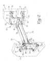
- the machine 1 comprises a bed 2 which provides support for a flat conveyor belt 3; the belt 3 is set substantially horizontally and carries and moves the slab 4 being worked. For convenience in the operations two lead-in rolls 5 are provided.
- the machine 1 also comprises two vertical uprights 6 and 7 of box construction, placed on one side of the belt 3 close to the opposed ends thereof.
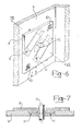
- each of said plates, 8,9 has a substantially rectangular shape, and is supported in a vertical position within a respective one of the uprights 6,7, it being adjustably positioned along said upright (6,7) between an upper position and a lower position. More specifically, each plate 8,9 is supported slidably on two straight guides 11 set at 45° off the vertical.
- the upright 6 also includes means of locking the plates 8 and 9, such as bolts, all indicated at 10.
- the upright 6 supports, through the two plates 8 and 9, a double articulated parallelogram, generally indicated at 13, hereinafter referred to as DAP for brevity.
- the DAP 13 comprises an upper crank lever 14 mounted pivotally on a pivot pin 15, carried on the upper plate 8, and a lower crank lever 16 mounted pivotally on a pivot pin 17, carried on the lower plate 9.
- Said pivot pins 15,17 define the fixed side 12 of the DAP 13 which extends across the upright 6 perpendicularly to the plane of the conveyor belt 3.
- the crank levers 14 and 16 are interlinked by two parallel connecting rods 18 and 19, associated with the crank levers 14 and 16 by pins 20,21 and 22,23, respectively.
- the upright 7 supports two plates (not shown in the drawings) being mirror- images of the plates 8 and 9, whereon a DAP 24 is mounted which is identical to and confronts the DAP 13;
- the DAP 24 comprises, like the DAP 13, an upper crank lever 25 journalled to a pivot pin 26 which is carried on the upper plate (not shown), a lower crank lever 27 journalled to a pivot pin 28 carried on the lower plate (not shown), and two parallel connecting rods 29 and 30;
- the connecting rods 29 and 30 are respectively associated with the crank lever 25 through pins 31 and 32, and with the crank lever 27 through pins 33 and 34.
- the two DAP's 13 and 24 support a tool holding table 35.
- the table 35 is provided with four pins 36,37,38,39, in opposed and aligned pairs (36 with 38, 37 with 39); by means of said pins 36,37,38,39, the table 35 can be associated with the crank levers 14,16,25,27.
- the table is guided by the two DAP's 13 and 24, and is, therefore, movable angularly about an axis of rotation 44 extending parallel to the axes of the crank pins 15,17,26,28.
- the table 35 supports a plurality of power-driven tools 45; more specifically, each tool 45 comprises an electric motor 46, a cup grinding wheel 47, and a device for shifting the grinding wheel along its rotation axis; this device is of conventional design and is only_schematically illustrated in the drawings at 48.
- the machine 1 further comprises means of shifting angularly the crank levers (and hence, the table 35 with the tools 45) about their respective pins.
- Such means comprise, for each DAP, a sprocket wheel 49 attached to the crank lever 14 and mounted coaxially pivotally on the pin 1,5.
- the wheel 49 is kinematically connected to a drive unit, such as a cylinder-piston unit 50 which drives a rack 51 in engagement with a pinion gear 52; the pinion 52 is coaxially fast with a sprocket wheel 53, connected to the wheel 49 by a chain 54, for rotation therewith.
- the drawing figures only show details of the DAP 13, those relating to the DAP 24 being quite identical.
- the table 35 with the tools 45, the two DAP's 13,24, the plates 8,9 for supporting and adjustably positioning the crank pins 15,17,26,28 on said DAP's, and the means (49,50,51, 52,53,54) of shifting the crank levers angularly about their respective pivot pins form jointly a tool holding device.
- the machine 1 also includes a counterweighing device resisting the rotation of the crank levers under the weight of the tool holding table 35. More specifically, that device comprises, for each of the two DAP's 13,24, a flexible cable 56 attached with one end to the upper crank lever 14,25 of the DAP, and with the other end to a counterweight 57 located at the end of an arm 58 attached pivotally to its respective upright 6,7. Each cable 56 is guided on six pulleys 59,60,61,62,63,64.
- the machine 1 operates as follows.
- a slab 4 to be polished having a circular profile edge 4a, is laid onto the conveyor belt 3 and entrained thereby in a position with the axis of the edge 4a coincident with the axis 44.
- the edge to be polished contacts in succession all of the grinding wheels 47, as with conventional machines.
- the tool holding table 35 of this machine 1 is constantly moved angularly about the axis 44, to repeatedly move back and forth over an arc of 180°.
- the cylinder-piston unit 50 is driven constantly in both directions; the motion of the piston is thus transferred (via the rack 51, pinion 52, sprocket 53, chain 54, and sprocket 49) to the crank levers of the DAP's which will keep moving angularly back and forth about their respective pivot pins. Similarly to the crank levers, the table 35 will be moved back and forth about the axis 44.
- the grinding wheels 47 on the table 35 will, therefore, follow the-surface of the circular profile edge 4a.
- the grinding wheels 47 should be shifted axially on the table 35 by means of the devices 48.
- the 45° inclination of the guides provides for high locating accuracy.
- the machine 1 can also work flat edges, in the same way as traditional machines; in fact, it would be sufficient to stop the cylinder-piston unit 50 and lock the grinding wheels 47 in a position providing a sought inclination on the slab.
Landscapes
- Engineering & Computer Science (AREA)
- Mechanical Engineering (AREA)
- Finish Polishing, Edge Sharpening, And Grinding By Specific Grinding Devices (AREA)
- Machine Tool Units (AREA)
- Processing Of Stones Or Stones Resemblance Materials (AREA)
- Specific Conveyance Elements (AREA)
- Grinding And Polishing Of Tertiary Curved Surfaces And Surfaces With Complex Shapes (AREA)
Priority Applications (3)
| Application Number | Priority Date | Filing Date | Title |
|---|---|---|---|
| EP85830062A EP0197233B1 (de) | 1985-03-12 | 1985-03-12 | Maschine zur Bearbeitung von mit Kreisbogen profilierten Kanten von Platten aus Marmor, Granit und ähnlichen Materialien |
| AT85830062T ATE36263T1 (de) | 1985-03-12 | 1985-03-12 | Maschine zur bearbeitung von mit kreisbogen profilierten kanten von platten aus marmor, granit und aehnlichen materialien. |
| DE8585830062T DE3564212D1 (en) | 1985-03-12 | 1985-03-12 | A machine for working circular profile edges of slabs of marble, granite, and the like |
Applications Claiming Priority (1)
| Application Number | Priority Date | Filing Date | Title |
|---|---|---|---|
| EP85830062A EP0197233B1 (de) | 1985-03-12 | 1985-03-12 | Maschine zur Bearbeitung von mit Kreisbogen profilierten Kanten von Platten aus Marmor, Granit und ähnlichen Materialien |
Publications (2)
| Publication Number | Publication Date |
|---|---|
| EP0197233A1 true EP0197233A1 (de) | 1986-10-15 |
| EP0197233B1 EP0197233B1 (de) | 1988-08-10 |
Family
ID=8194675
Family Applications (1)
| Application Number | Title | Priority Date | Filing Date |
|---|---|---|---|
| EP85830062A Expired EP0197233B1 (de) | 1985-03-12 | 1985-03-12 | Maschine zur Bearbeitung von mit Kreisbogen profilierten Kanten von Platten aus Marmor, Granit und ähnlichen Materialien |
Country Status (3)
| Country | Link |
|---|---|
| EP (1) | EP0197233B1 (de) |
| AT (1) | ATE36263T1 (de) |
| DE (1) | DE3564212D1 (de) |
Cited By (4)
| Publication number | Priority date | Publication date | Assignee | Title |
|---|---|---|---|---|
| EP0296126A3 (en) * | 1987-05-22 | 1990-06-13 | Marmo Meccanica - S.P.A. | Device for supporting and moving the work-tool table on automatic machines for polishing the rounded edges of marble, granite plates and the same |
| WO1995016546A1 (en) * | 1993-12-14 | 1995-06-22 | Grobi A/S | Edge grinder for mechanically rounding off edges of structural members |
| ES2143347A1 (es) * | 1996-07-10 | 2000-05-01 | Crespillo Manuel Arjona | Maquina para pulir cantos de piezas de marmol. |
| EP1518641A1 (de) * | 2003-09-29 | 2005-03-30 | MONTRESOR & C. S.r.l. | Vorrichtung zum Polieren von Marmor- oder Stein-Platten mit um einen Drehpunkt rotierenden Kopf |
Citations (2)
| Publication number | Priority date | Publication date | Assignee | Title |
|---|---|---|---|---|
| GB1108766A (en) * | 1965-05-11 | 1968-04-03 | Bielefelder Union Koch | Panel edge grinding machine |
| CH490919A (de) * | 1967-01-06 | 1970-05-31 | Herbert Cleff Peter | Maschine zur Endbearbeitung von Zahnrädern |
-
1985
- 1985-03-12 EP EP85830062A patent/EP0197233B1/de not_active Expired
- 1985-03-12 AT AT85830062T patent/ATE36263T1/de not_active IP Right Cessation
- 1985-03-12 DE DE8585830062T patent/DE3564212D1/de not_active Expired
Patent Citations (2)
| Publication number | Priority date | Publication date | Assignee | Title |
|---|---|---|---|---|
| GB1108766A (en) * | 1965-05-11 | 1968-04-03 | Bielefelder Union Koch | Panel edge grinding machine |
| CH490919A (de) * | 1967-01-06 | 1970-05-31 | Herbert Cleff Peter | Maschine zur Endbearbeitung von Zahnrädern |
Cited By (7)
| Publication number | Priority date | Publication date | Assignee | Title |
|---|---|---|---|---|
| EP0296126A3 (en) * | 1987-05-22 | 1990-06-13 | Marmo Meccanica - S.P.A. | Device for supporting and moving the work-tool table on automatic machines for polishing the rounded edges of marble, granite plates and the same |
| WO1995016546A1 (en) * | 1993-12-14 | 1995-06-22 | Grobi A/S | Edge grinder for mechanically rounding off edges of structural members |
| US5762542A (en) * | 1993-12-14 | 1998-06-09 | Grobi A/S | Edge grinder for mechanically rounding off edges of structural members |
| CN1071619C (zh) * | 1993-12-14 | 2001-09-26 | 格罗比有限公司 | 以机械方式倒圆构件边缘用的磨边装置 |
| ES2143347A1 (es) * | 1996-07-10 | 2000-05-01 | Crespillo Manuel Arjona | Maquina para pulir cantos de piezas de marmol. |
| EP1518641A1 (de) * | 2003-09-29 | 2005-03-30 | MONTRESOR & C. S.r.l. | Vorrichtung zum Polieren von Marmor- oder Stein-Platten mit um einen Drehpunkt rotierenden Kopf |
| US7070482B2 (en) | 2003-09-29 | 2006-07-04 | Nicola Montresor | Marble or stone slab polishing machine provided with a rotating head mounted on a fulcrum |
Also Published As
| Publication number | Publication date |
|---|---|
| ATE36263T1 (de) | 1988-08-15 |
| DE3564212D1 (en) | 1988-09-15 |
| EP0197233B1 (de) | 1988-08-10 |
Similar Documents
| Publication | Publication Date | Title |
|---|---|---|
| CN212531373U (zh) | 一种工件翻转装置 | |
| US6142050A (en) | Cutting machine for elongate workpieces | |
| GB1588482A (en) | Woodworking machines | |
| CN112008559A (zh) | 一种高效多功用精确打磨设备 | |
| US5216844A (en) | Process for the automatic machining of edges of glass plates and apparatus for carrying out said process | |
| US5759222A (en) | Glass-plate working apparatus | |
| CN112757066A (zh) | 一种成型无心外圆磨床 | |
| EP0558533A1 (de) | Schneid- und schleifvorrichtung für einen glasscheibenrand. | |
| US20220297347A1 (en) | Machine for cutting slabs, particularly made of marble, granite, glass and composite materials | |
| EP0197233B1 (de) | Maschine zur Bearbeitung von mit Kreisbogen profilierten Kanten von Platten aus Marmor, Granit und ähnlichen Materialien | |
| CN215035972U (zh) | 一种成型无心外圆磨床 | |
| CN108857751B (zh) | 一种石材打磨机 | |
| CN217914622U (zh) | 一种复合型打磨机械臂及其制成的打磨加工工作站 | |
| US4211040A (en) | Process for machining silicon rods and tubes by abrasion | |
| JPH06218702A (ja) | 連続して移動する板状加工物の端部加工用装置 | |
| US4136489A (en) | Grinding and polishing machine | |
| JPH03149146A (ja) | 自動彫刻盤 | |
| JPH01500178A (ja) | 工作機械のための工具交換装置 | |
| JPS60180758A (ja) | 研削装置 | |
| EP0142655A2 (de) | Vorrichtung zum Schleifen der Schweisszone von Radkränzen von Rädern von Fahrrädern und Kraftfahrzeugen | |
| CN220944765U (zh) | 打磨设备自动上料装置 | |
| CN218801325U (zh) | 一种花岗岩栏杆花瓶柱全自动打磨抛光设备 | |
| IES20030933A2 (en) | Workpiece finishing | |
| CN119526144B (zh) | 一种轴承配件打磨器 | |
| CN213054209U (zh) | 一种卧式石材打磨设备 |
Legal Events
| Date | Code | Title | Description |
|---|---|---|---|
| PUAI | Public reference made under article 153(3) epc to a published international application that has entered the european phase |
Free format text: ORIGINAL CODE: 0009012 |
|
| AK | Designated contracting states |
Kind code of ref document: A1 Designated state(s): AT BE CH DE FR GB IT LI LU NL SE |
|
| 17P | Request for examination filed |
Effective date: 19870108 |
|
| 17Q | First examination report despatched |
Effective date: 19871013 |
|
| GRAA | (expected) grant |
Free format text: ORIGINAL CODE: 0009210 |
|
| AK | Designated contracting states |
Kind code of ref document: B1 Designated state(s): AT BE CH DE FR GB IT LI LU NL SE |
|
| PG25 | Lapsed in a contracting state [announced via postgrant information from national office to epo] |
Ref country code: IT Free format text: LAPSE BECAUSE OF FAILURE TO SUBMIT A TRANSLATION OF THE DESCRIPTION OR TO PAY THE FEE WITHIN THE PRESCRIBED TIME-LIMIT;WARNING: LAPSES OF ITALIAN PATENTS WITH EFFECTIVE DATE BEFORE 2007 MAY HAVE OCCURRED AT ANY TIME BEFORE 2007. THE CORRECT EFFECTIVE DATE MAY BE DIFFERENT FROM THE ONE RECORDED. Effective date: 19880810 Ref country code: SE Effective date: 19880810 Ref country code: NL Effective date: 19880810 Ref country code: FR Free format text: THE PATENT HAS BEEN ANNULLED BY A DECISION OF A NATIONAL AUTHORITY Effective date: 19880810 Ref country code: BE Effective date: 19880810 Ref country code: AT Effective date: 19880810 |
|
| REF | Corresponds to: |
Ref document number: 36263 Country of ref document: AT Date of ref document: 19880815 Kind code of ref document: T |
|
| REF | Corresponds to: |
Ref document number: 3564212 Country of ref document: DE Date of ref document: 19880915 |
|
| EN | Fr: translation not filed | ||
| NLV1 | Nl: lapsed or annulled due to failure to fulfill the requirements of art. 29p and 29m of the patents act | ||
| PGFP | Annual fee paid to national office [announced via postgrant information from national office to epo] |
Ref country code: CH Payment date: 19890215 Year of fee payment: 5 |
|
| PGFP | Annual fee paid to national office [announced via postgrant information from national office to epo] |
Ref country code: DE Payment date: 19890228 Year of fee payment: 5 |
|
| REG | Reference to a national code |
Ref country code: CH Ref legal event code: PFA Free format text: C.M.P.I. S.R.L. |
|
| PG25 | Lapsed in a contracting state [announced via postgrant information from national office to epo] |
Ref country code: GB Effective date: 19890312 |
|
| PG25 | Lapsed in a contracting state [announced via postgrant information from national office to epo] |
Ref country code: LU Free format text: LAPSE BECAUSE OF NON-PAYMENT OF DUE FEES Effective date: 19890331 |
|
| PLBE | No opposition filed within time limit |
Free format text: ORIGINAL CODE: 0009261 |
|
| STAA | Information on the status of an ep patent application or granted ep patent |
Free format text: STATUS: NO OPPOSITION FILED WITHIN TIME LIMIT |
|
| 26N | No opposition filed | ||
| GBPC | Gb: european patent ceased through non-payment of renewal fee | ||
| PG25 | Lapsed in a contracting state [announced via postgrant information from national office to epo] |
Ref country code: LI Effective date: 19900331 Ref country code: CH Effective date: 19900331 |
|
| REG | Reference to a national code |
Ref country code: CH Ref legal event code: PL |
|
| PG25 | Lapsed in a contracting state [announced via postgrant information from national office to epo] |
Ref country code: DE Effective date: 19901201 |