EP0197163A1 - Véhicule pliant, en particulier du type à deux roues - Google Patents
Véhicule pliant, en particulier du type à deux roues Download PDFInfo
- Publication number
- EP0197163A1 EP0197163A1 EP85103880A EP85103880A EP0197163A1 EP 0197163 A1 EP0197163 A1 EP 0197163A1 EP 85103880 A EP85103880 A EP 85103880A EP 85103880 A EP85103880 A EP 85103880A EP 0197163 A1 EP0197163 A1 EP 0197163A1
- Authority
- EP
- European Patent Office
- Prior art keywords
- steering column
- main frame
- vehicle according
- pins
- sections
- Prior art date
- Legal status (The legal status is an assumption and is not a legal conclusion. Google has not performed a legal analysis and makes no representation as to the accuracy of the status listed.)
- Withdrawn
Links
Images


Classifications
-
- B—PERFORMING OPERATIONS; TRANSPORTING
- B62—LAND VEHICLES FOR TRAVELLING OTHERWISE THAN ON RAILS
- B62K—CYCLES; CYCLE FRAMES; CYCLE STEERING DEVICES; RIDER-OPERATED TERMINAL CONTROLS SPECIALLY ADAPTED FOR CYCLES; CYCLE AXLE SUSPENSIONS; CYCLE SIDE-CARS, FORECARS, OR THE LIKE
- B62K15/00—Collapsible or foldable cycles
- B62K15/006—Collapsible or foldable cycles the frame being foldable
- B62K15/008—Collapsible or foldable cycles the frame being foldable foldable about 2 or more axes
Definitions
- This invention relates to a collapsible vehicle, particularly of the two-wheeled type.
- Most embodiments usually provide a main frame which may be folded up to reduce the frame length dimension.
- Another object of this invention is to provide a collapsible vehicle which, owing to its peculiar constructive characteristics can give full assurance of being reliable and safe to use.
- a not least object of this invention is to provide a collapsible vehicle which can be easily formed from commercially available elements and materials, and is competitive from a purely economical standpoint.
- a collapsible vehicle particularly of the two-wheeled type comprising a main frame supporting at least one rear wheel and a steering column pivotally connected to said main frame and supporting at least one front wheel, characterized in that it comprises a saddle holder connected to said main frame and tiltable toward said main frame to bring said saddle forward of the main frame, the upper section of said steering column being connected to said steering column for tilting toward said main frame, the handle bar sections connected to said upper steering column section being tiltable toward said upper steering column section.
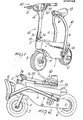
- this collapsible vehicle particularly of the two-wheeled type is schematically depicted therein as a motorcycle, and may have, of course, any other suitable configuration; that vehicle comprises a main frame 1 which is advantageously of elongate box type design.
- the frame 1 supports a front wheel, indicated at 2, and a steering column 3 connected pivotally to the frame 1.
- the steering column is connected to a front fork 4 whereto a front wheel 5 is connected.
- a first feature of the invention is that the vehicle is provided with a saddle holder consisting of a rod-like body 10 which extends substantially into a U-like shape and has legs 11 which enclose the frame 1 laterally and are joined by a joining section 12 whereto the saddle 13 is connected.
- the legs 11 of the rod-like body 10 have, at the bottom free ends thereof, pins 15, which may be replaced, however, with a single cross pin, which are engaged slidingly in contoured slots 16 defined on the sides 1a of the frame 1.
- the contoured slots 16 have a substantially vertical section 16a, wherein the pins 15 are engaged, with the holder in its position for use, which merges with a mainly horizontal section 16b extending toward the rear of the frame 1.
- the legs 11, at a middle portion thereof close to their free ends, are joined by a crosspiece 18 which is hinged to one end of rods 19 which are articulated with their other ends to a front crosspiece 20 carried on the sides 1a of the frame 1.
- rubber couplings 21 for damping any vibrations which may be generated.
- connection described above forms in practice a three-hinge arch consisting of the pins 15, crosspiece 18, and front crosspiece 20; the three-hinge arch is fixed, on locking the pin 15 in place, and in that position, supports the saddle holder 10 at a position close to the vertical.
- the pins 15, as mentioned above, are received slidably within the slots 16 such that the holder 10 can be tilted toward the frame by utilizing the sliding travel of the free ends of the pins 15 towards the rear of the frame.
- the saddle 13 In the tilted position, the saddle 13 is located over the front wheel 5, forward of the frame.
- ratchet pawls 25 advantageously hinged to the frame 1 and having a hooked end 26 in engagement with the pins 15 and at the other end a return spring 27 holding the pawls in the locked position, are provided.
- a joining rod 28 is provided which is passed through the frame sides and enables the pawls to be actuated simultaneously by acting on a single pawl.
- the pins 15 On disengaging, the pins 15 may be slid-in the slots 16, thus moving the pins 15 rearward; from the frame, with consequent tilting toward the front portion of the holder 10.
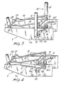
- the frame 1 supports a steering column 3 pivotally therein;
- the steering column 3 has an upper section, generally indicated at 30, which is connected to the lower section of the steering column 3 for hinged connection and consequent tilting movement about a perpendicular axis to the main axis of the steering column.
- the steering column 3 has a lower plate 31 connected thereto which is hinged to an upper plate 32 rigidly connected to the upper section 30.
- the hinge axis is substantially perpendicular to the main direction of the steering column 3.
- the lower plate 31 has, at the remote end from the hinge 33 connecting it to the upper plate 32, a cross detent 34 which may be hooked by the end of a stirrup 35 of substantially U-like shape which is hinged at 37 to the bottom ends of connecting rods 36 which are hinged with their other ends at 38 to the upper section 30.
- the stirrup 35 has, at the free ends of its legs, a hooking portion 39 which engages with the detent 34.
- An elastic means is then provided which comprises a spring 40 connected between a connecting rod 36 and the joining section 35a of the stirrup 35, which is located remotely from the hinge axis 37 with respect to the hooking portions 39.
- a handle bar Connected to the top end of the upper section 30 is a handle bar, generally indicated at 50, which has a center body 51 connected to the top end of the section 30 and curved side edges 52 which perform a camming function.
- the center body 51 is connected as by hinges to the inward ends of the sections 55 of the handle bar through hinge pins 56 which are carried on the center body.
- the sections 55 have, at a portion thereof close to the hinge pins 56, slots 57 elongated in the axial direction, which receive slidably therein cross pins 60 which act by contact on the cited side edges 52 of the center body 51.
- elastic means comprising traction springs 61 which hold the pins 60 pressed elastically against the edges 52.
- edges 52 define upper notches 65 wherein the pins 60 are inserted to lock the sections 55 in the open position for use. Also provided on the edges 52 are lower notches 66 wherein the pins 60 are engageable to lack the sections 55 in a position close against the upper section 30.
- edges 52 are shaped to vary the elastic action of the traction springs 61, so as to adjust the force which holds the sections 55 in the set position.
- the saddle holder is tilted down by pivoting it toward the front, utilizing the sliding feature of the pins 15 in the contoured slot 16 defined in the main frame sides, thereby the holder 10 can be folded laterally to the frame to bring the saddle 13 to- the front of the frame.
- the materials used may be any ones depending on requirements.
Priority Applications (1)
| Application Number | Priority Date | Filing Date | Title |
|---|---|---|---|
| EP85103880A EP0197163A1 (fr) | 1985-04-01 | 1985-04-01 | Véhicule pliant, en particulier du type à deux roues |
Applications Claiming Priority (1)
| Application Number | Priority Date | Filing Date | Title |
|---|---|---|---|
| EP85103880A EP0197163A1 (fr) | 1985-04-01 | 1985-04-01 | Véhicule pliant, en particulier du type à deux roues |
Publications (1)
| Publication Number | Publication Date |
|---|---|
| EP0197163A1 true EP0197163A1 (fr) | 1986-10-15 |
Family
ID=8193412
Family Applications (1)
| Application Number | Title | Priority Date | Filing Date |
|---|---|---|---|
| EP85103880A Withdrawn EP0197163A1 (fr) | 1985-04-01 | 1985-04-01 | Véhicule pliant, en particulier du type à deux roues |
Country Status (1)
| Country | Link |
|---|---|
| EP (1) | EP0197163A1 (fr) |
Cited By (12)
| Publication number | Priority date | Publication date | Assignee | Title |
|---|---|---|---|---|
| US5947500A (en) * | 1996-02-23 | 1999-09-07 | Daewoo Uk Ltd | Cycle frame assembly |
| DE10025923A1 (de) * | 2000-05-27 | 2001-11-29 | Kuji Sports Co | Zusammenklappbarer Roller |
| DE10037261C1 (de) * | 2000-07-28 | 2002-03-07 | Speedliner Deutschland Gmbh | Tretroller |
| GB2379200A (en) * | 2001-09-04 | 2003-03-05 | Far Great Plastics Ind Co Ltd | Folding bicycle |
| WO2005035347A1 (fr) * | 2003-10-15 | 2005-04-21 | Bied Dominique | Bicyclette pliable et procédé de pliage |
| FR2892996A1 (fr) * | 2006-10-27 | 2007-05-11 | Bied Dominique | Bicyclette pliable et procede de pliage |
| WO2007113179A1 (fr) * | 2006-04-04 | 2007-10-11 | Studio Moderna Sa | Mécanisme à verrouillage automatique |
| ES2368393A1 (es) * | 2011-07-15 | 2011-11-17 | Joaquín Montero Basqueseaux | Conjunto de manillar de bicicleta. |
| WO2013011181A3 (fr) * | 2011-07-15 | 2013-03-07 | Montero Basqueseaux Joaquin | Ensemble de guidon de bicyclette |
| FR2998252A1 (fr) * | 2012-11-22 | 2014-05-23 | Decathlon Sa | Ensemble de verrouillage deverrouillable en rotation |
| WO2017025063A1 (fr) * | 2015-08-13 | 2017-02-16 | 北京一英里科技有限公司 | Véhicule électrique pliable et châssis repliable |
| CN106627929A (zh) * | 2015-12-03 | 2017-05-10 | 北京英里科技有限公司 | 可折叠电动车及其车架 |
Citations (2)
| Publication number | Priority date | Publication date | Assignee | Title |
|---|---|---|---|---|
| FR2384667A1 (fr) * | 1977-03-25 | 1978-10-20 | Tomy Kogyo Co | Bicyclette pliante |
| WO1983003232A1 (fr) * | 1982-03-16 | 1983-09-29 | Csizmadia, Lajos | Velo pliable pouvant etre porte dans un sac |
-
1985
- 1985-04-01 EP EP85103880A patent/EP0197163A1/fr not_active Withdrawn
Patent Citations (2)
| Publication number | Priority date | Publication date | Assignee | Title |
|---|---|---|---|---|
| FR2384667A1 (fr) * | 1977-03-25 | 1978-10-20 | Tomy Kogyo Co | Bicyclette pliante |
| WO1983003232A1 (fr) * | 1982-03-16 | 1983-09-29 | Csizmadia, Lajos | Velo pliable pouvant etre porte dans un sac |
Cited By (21)
| Publication number | Priority date | Publication date | Assignee | Title |
|---|---|---|---|---|
| US5947500A (en) * | 1996-02-23 | 1999-09-07 | Daewoo Uk Ltd | Cycle frame assembly |
| DE10025923A1 (de) * | 2000-05-27 | 2001-11-29 | Kuji Sports Co | Zusammenklappbarer Roller |
| DE10037261C1 (de) * | 2000-07-28 | 2002-03-07 | Speedliner Deutschland Gmbh | Tretroller |
| GB2379200A (en) * | 2001-09-04 | 2003-03-05 | Far Great Plastics Ind Co Ltd | Folding bicycle |
| US7584978B2 (en) | 2003-10-15 | 2009-09-08 | Dominique Bied | Foldable bicycle and method of folding |
| WO2005035347A1 (fr) * | 2003-10-15 | 2005-04-21 | Bied Dominique | Bicyclette pliable et procédé de pliage |
| FR2861048A1 (fr) * | 2003-10-15 | 2005-04-22 | Bied Dominique | Bicyclette pliable et procede de pliage |
| US7762570B2 (en) | 2006-04-04 | 2010-07-27 | Studio Moderna Sa | Self-locking mechanism |
| WO2007113179A1 (fr) * | 2006-04-04 | 2007-10-11 | Studio Moderna Sa | Mécanisme à verrouillage automatique |
| JP2009532645A (ja) * | 2006-04-04 | 2009-09-10 | ステュディオ モデルナ エスアー | セルフロック機構 |
| AU2007233751B2 (en) * | 2006-04-04 | 2010-12-02 | Studio Moderna Sa | Self-locking mechanism |
| EA014679B1 (ru) * | 2006-04-04 | 2010-12-30 | Студио Модерна Са | Самофиксирующийся механизм |
| KR101028876B1 (ko) | 2006-04-04 | 2011-04-12 | 스튜디오 모더나 사 | 자동-잠금 기구 |
| FR2892996A1 (fr) * | 2006-10-27 | 2007-05-11 | Bied Dominique | Bicyclette pliable et procede de pliage |
| ES2368393A1 (es) * | 2011-07-15 | 2011-11-17 | Joaquín Montero Basqueseaux | Conjunto de manillar de bicicleta. |
| WO2013011181A3 (fr) * | 2011-07-15 | 2013-03-07 | Montero Basqueseaux Joaquin | Ensemble de guidon de bicyclette |
| FR2998252A1 (fr) * | 2012-11-22 | 2014-05-23 | Decathlon Sa | Ensemble de verrouillage deverrouillable en rotation |
| WO2017025063A1 (fr) * | 2015-08-13 | 2017-02-16 | 北京一英里科技有限公司 | Véhicule électrique pliable et châssis repliable |
| CN106627929A (zh) * | 2015-12-03 | 2017-05-10 | 北京英里科技有限公司 | 可折叠电动车及其车架 |
| CN106627928A (zh) * | 2015-12-03 | 2017-05-10 | 北京英里科技有限公司 | 用于助动车的可折叠车架 |
| CN106627929B (zh) * | 2015-12-03 | 2023-07-07 | 北京一英里科技有限公司 | 可折叠电动车及其车架 |
Similar Documents
| Publication | Publication Date | Title |
|---|---|---|
| US4611818A (en) | Collapsible vehicle, particularly of the two-wheeled type | |
| KR101139065B1 (ko) | 접이식 자전거 프레임 | |
| US5052706A (en) | Foldable bicycle | |
| EP0197163A1 (fr) | Véhicule pliant, en particulier du type à deux roues | |
| US4457529A (en) | Folding tricycle | |
| US5040709A (en) | Water bottle and cage for a bicycle | |
| US6935649B2 (en) | Foldable tricycle | |
| US7543840B2 (en) | Collapsible golf push cart | |
| EP0058526B1 (fr) | Bicyclette pliable et portable pouvant servir de chariot | |
| US7341268B2 (en) | Foldable bicycle | |
| US4022485A (en) | Collapsible bicycle | |
| US6312005B1 (en) | Stroller with three wheels | |
| US6276694B1 (en) | Children's cycle | |
| US20020140193A1 (en) | Folding and locking arrangement for collapsible scooter | |
| US6491312B2 (en) | Scooter steering control | |
| US5496054A (en) | Folding collapsible frame for golf carts | |
| US6969078B2 (en) | Third wheel collapsing device for a golf club cart | |
| GB2324071A (en) | Collapsible bicycle | |
| EP0229597B1 (fr) | Cyclomoteur pliant avec support de selle rabattable | |
| US5582562A (en) | Collapsible riding type exercise apparatus | |
| US20050082778A1 (en) | Cambering vehicle having resilient coupling | |
| US6048037A (en) | Detachable device of a stroller wheel | |
| US20040000770A1 (en) | One-sides sprung arm of a bicycle front wheel | |
| US5643150A (en) | Foldable exerciser horse | |
| EP0992422A2 (fr) | Bicyclette pliable |
Legal Events
| Date | Code | Title | Description |
|---|---|---|---|
| PUAI | Public reference made under article 153(3) epc to a published international application that has entered the european phase |
Free format text: ORIGINAL CODE: 0009012 |
|
| AK | Designated contracting states |
Kind code of ref document: A1 Designated state(s): AT BE CH DE FR GB LI LU NL SE |
|
| 17P | Request for examination filed |
Effective date: 19870415 |
|
| 17Q | First examination report despatched |
Effective date: 19880310 |
|
| STAA | Information on the status of an ep patent application or granted ep patent |
Free format text: STATUS: THE APPLICATION IS DEEMED TO BE WITHDRAWN |
|
| 18D | Application deemed to be withdrawn |
Effective date: 19881102 |
|
| RIN1 | Information on inventor provided before grant (corrected) |
Inventor name: CAMMARATA, ITALO |