EP0196832A2 - Mirror finish polisher - Google Patents
Mirror finish polisher Download PDFInfo
- Publication number
- EP0196832A2 EP0196832A2 EP86302062A EP86302062A EP0196832A2 EP 0196832 A2 EP0196832 A2 EP 0196832A2 EP 86302062 A EP86302062 A EP 86302062A EP 86302062 A EP86302062 A EP 86302062A EP 0196832 A2 EP0196832 A2 EP 0196832A2
- Authority
- EP
- European Patent Office
- Prior art keywords
- liquid
- polisher
- mirror finish
- visco
- front plate
- Prior art date
- Legal status (The legal status is an assumption and is not a legal conclusion. Google has not performed a legal analysis and makes no representation as to the accuracy of the status listed.)
- Granted
Links
Images


Classifications
-
- B—PERFORMING OPERATIONS; TRANSPORTING
- B24—GRINDING; POLISHING
- B24D—TOOLS FOR GRINDING, BUFFING OR SHARPENING
- B24D13/00—Wheels having flexibly-acting working parts, e.g. buffing wheels; Mountings therefor
- B24D13/14—Wheels having flexibly-acting working parts, e.g. buffing wheels; Mountings therefor acting by the front face
- B24D13/147—Wheels having flexibly-acting working parts, e.g. buffing wheels; Mountings therefor acting by the front face comprising assemblies of felted or spongy material; comprising pads surrounded by a flexible material
-
- B—PERFORMING OPERATIONS; TRANSPORTING
- B24—GRINDING; POLISHING
- B24B—MACHINES, DEVICES, OR PROCESSES FOR GRINDING OR POLISHING; DRESSING OR CONDITIONING OF ABRADING SURFACES; FEEDING OF GRINDING, POLISHING, OR LAPPING AGENTS
- B24B29/00—Machines or devices for polishing surfaces on work by means of tools made of soft or flexible material with or without the application of solid or liquid polishing agents
-
- B—PERFORMING OPERATIONS; TRANSPORTING
- B24—GRINDING; POLISHING
- B24D—TOOLS FOR GRINDING, BUFFING OR SHARPENING
- B24D13/00—Wheels having flexibly-acting working parts, e.g. buffing wheels; Mountings therefor
Definitions
- This invention relates to a polisher for mirror-finishing workpiece surfaces, and more particularly to a polisher which is extremely small in rate or in total amount of removal as compared with the case of the improvement of shape accuracy by the common electrochemical machining and which can improve the surface roughness up to the level of 1/100 ⁇ m.
- Mirror-finished stainless steel sheets are increasingly used as architectural interior and exterior furnishings and as silicon solar cell base plates.
- the conventional buffing operation entails another problem that it is difficult to improve the working environment by suppressing the dust which is scattered to a considerable amount during the polishing operation.
- the polisher construction which is capable of performing the combined electrolytic-abrasive polishing can be realized only after recognition of the fact that the electrolyte is used only in a small amount in the mirror finishing operation in which the machining rate is far smaller than in a profiling operation as mentioned hereinbefore.
- a mirror finish polisher which comprises: a tool base to be attached to the fore end of a spindle of a rotational drive and constituted by a disk-like front plate and a rear plate integrally joined at peripheral marginal edge portions to the front plate, forming aliquid pool in peripheral portions on the back side of the front plate; a polishing liquid inlet formed at the center of the rear plate of the tool base in such a manner as to circumvent the spindle; a liquid supply tube opened into the polishing liquid inlet; a multitude of liquid outlets opened in the front plate at positions slightly inward of the peripheral edge thereof; a liquid-permeable visco-elastic polishing member attached to the front plate and having a machining face retaining abrasive grains thereon and deformable in conformity with the shape of a work surface.
- the visco-elastic polishing member Upon rotating the polisher of the above-described construction by a rotational drive while supplying a polishing liquid through the liquid inlet, the visco-elastic polishing member fits the shape of a workpiece by deforming itself in conformity with the undulations on the surface of the workpiece if any to make it possible to give a mirror finish to an arbitrary free curved surface.
- the liquid which has been supplied to the tool base is temporarily reserved in the peripheral liquid pool and distributed stably to the entire contacting area of the visco-elastic polishing member and the workpiece by the centrifugal force resulting from the rotation of the tool base.
- the liquid is uniformly distributed to the entire machining surface of the visco-elastic polishing member, without forming such splitted streams taking place at toward those portions where the contact pressure of the visco-elastic polishing member with the workpiece is lower or toward at those portions where a gap is formed due to existence of undulations on the surface of the latter, that are indispensable to the flow supplied in the high pressure from the center of the tool base. Accordingly, it is possible to polish a work-piece by contacting therewith only the peripheral portions of the visco-elastic polishing member.
- the electrolytic-abrasive polisher 10 shown in Fig. 1 includes a pistol-shaped housing 1 accommodating a rotational drive motor 12 and a reducer 13 coupled with the output side of the motor to rotate a spindle 14 which is protruded from the housing 11 and has a tool 20 attached to the fore end thereof.
- the tool 20 which functions as an electrode in case of electrolytic polishing is constituted by a tool base 21 substantially of a disk-like shape and a visco-elastic polishing member 22 attached to the surface of the tool base.
- the tool base 21 includes a disk-like front plate 24 to be attached to the fore end of the spindle 14, and a rear plate 25 which is integrally joined to the front plate 21 at the peripheral edges thereof to form a liquid pool around and on the back side of the front plate 24.
- the front plate 24 is centrally provided with a recess 29 to receive therein a head portion of a screw 28 which fastens the tool base 21 to the spindle 14, and with a multitude of liquid outlet holes 30 at positions slightly inward of its peripheral edges.
- the rear plate 25 is formed with a liquid supply opening 31 centrally around the spindle 14, and a sliding contact surface 32 around the opening 31 for contact with a power supply shoe 33 which supplies electrolytic current as will be described hereinlater.
- the visco-elastic polishing member 22 which is attached to the surface of the tool base 21 is constituted by a liquid permeable visco-elastic material including sponge-like materials such as foamed polyurethane or other foamed synthetic resins or unwoven nylon fabric, which is in the form suitable for attachment to the surface of the tool base 21.
- a sponge-like material is employed as in the particular embodiment shown, it is provided with a cavity 34 which fits on the tool base 21 and mounted on the spindle 14 by fastening same to the spindle together with the tool base 21 by a screw 28 through a doubling plate 35.
- the visco-elastic polishing member 22 consists of unwoven nylon fabric or the like, its peripheral portions can be fixed to the surface of the tool base 21 by an adhesive or other suitable means and fastened to the spindle 14 through the doubling plate 35.
- the visco-elastic polishing member 22 may hold abrasive grains dispersedly on its surface or in its entire body.
- abrasive grains of alumina or the like may be fixedly bonded on an unwoven nylon fabric sheet or the like by the use of a synthetic resin bond which is mixed with the abrasive grains.
- loose abrasive grains may be supported in meshes of unwoven fabric.
- a multitude of liquid outlet holes 30 are formed in the front plate 24 at positions slightly inward of the peripheral edges of the tool base 21 for the purpose of forming a pool 26 of the polishing liquid or electrolyte in peripheral portions of the tool base 21, storing the liquid temporarily therein to feed same stably through a large number of liquid outlet holes 30. Accordingly, while the tool 20 is rotated, the liquid which flows out continuously through the liquid outlet holes 30 is fed to the contacting area between the visco-elastic polishing member 22 and a work around the peripheral portions of the tool 20 under the influence of centrifugal force. In addition, since the tool 20 has a high liquid holding capacity, it is possible to feed the liquid stably not only to a horizontally disposed curved surface but also to almost vertically disposed curved surface.
- a liquid feed pipe 38 which supplies the polishing liquid or electrolyte to polishing areas in the peripheral portions of the tool 20 has its inlet end 40 opened into one end of the housing 11 and its outlet end 41 opened into the tool base 21 through the liquid supply opening 31 which is formed centrally in the rear plate 25 around the spindle 14.
- the polishing liquid or electrolyte is simply poured into the liquid pool which is open to the atmosphere, so that it is possible to simplify the equipments for feeding the liquid under pressure.
- the liquid can be fed to the polisher without resorting to a pump, simply by locating a liquid reservoir at a slightly higher position that of the polisher.
- free abrasive grains may be admixed into the polishing liquid or electrolyte which is supplied through the liquid feed pipe 38. Especially in case of a polishing operation using fine grains, it is advantageous to use such free abrasive grains which can be uniformly distributed over the entire surface of the visco-elastic polishing member 22.
- the liquid which is supplied through the liquid feed pipe 38 serves to cool the polishing portions and to discharge the fine particles of the stock which is removed by polishing, performing the intended functions by the use of a relatively small amount of liquid similarly to electrolytic polishing.
- a power supply terminal 43 is provided at one end of the housing 11 to supply electrolytic current to the tool 20 through the power supply shoe 33 and the sliding surface 32 which is in contact with the shoe 33, and connectible to a power source (not shown) to conduct current across the workpiece and tool 20 serving as positive and negative electrodes, respectively.
- Indicated at 44 is a switch member which is manipulatable to actuate the rotational drive 12.
- the above-described electrolytic-abrasive polisher can be used as a portable machine which is lightly pressed by hand against a surface of a workpiece which need polishing, or it is mounted on a carriage which is freely movable in a horizontal plate to perform the polishing operation. As illustrated in Fig.
- the tool electrode 20 has a diameter of about 12-cm, it can give a mirror finish even to a work surface containing a certain degree of undula- .tions, since the peripheral portions of the visco-elastic polishing member 22 are suitably deformed into a shape which fits the surface profile of the workpiece when pressed thereagainst at a rotational speed of about several hundreds r.p.m. In this instance, the pressure which is imposed by the tool 20 on raised portions of the contacting surface of the workpiece 45 is naturally greater than the pressure imposed on lower surface portions, so that the amount of stock removal by the abrasive becomes greater on the raised surface portions. However, since relatively large raised and depressed surface portions are finished substantially to the same degree of roughness, works can be polished efficiently in a case where accuracy in shape is not severe. It suffices to supply the electrolyte at a flow rate of one litre per minute or less.
- the combined electrolytic-abrasive polishing can be suitably applied to polishing of free curved surfaces of various metallic products, particularly to surface polishing of stainless steels or the like.
- this automatic polishing machine includes a machine frame 50 formed by joining angles which are extended along the respective edges of a rectangular parallelepiped, and a two-dimensional automatic feed mechanism 53 is mounted on a support plate 51 which is in turn mounted on top of the machine frame 50.
- the automatic feed mechanism 53 which moves the polisher head 10 on a carriage 54 freely in perpendicularly intersecting X and Y directions in a horizontal plane, in cludes paired parallel X-direction guide rods 58 between a pair of support members 56 and 57 at the opposite ends of a base plate 55 which is fixed to the support plate 51.
- a feed screw 60 which is rotationally driven by a motor 58 on the support plate 55 is rotatably supported also in the support members 56 and 57 and threadedly engaged with the X -direction carriage 61 in which the guide rods 58 are slidably inserted to guide the movements of the carriage 61 in X-direction. Accordingly, upon rotating the feed screw 60 by the motor 59, the X-direction carriage 61 is moved in X-direction under guidance of the guide rods 58.
- slidably inserted in the X-direction carriage 61 are a pair of Y-direction guide rods 63 and a feed screw 64 which are disposed perpendicular to the X-direction guide rods 58.
- These guide rods 63 are fixedly mounted between support members 65 and 66 at the opposite ends of the carriage 54, and the feed screw 64 is rotatably supported on-the two support members 65 and 66, with one end of the feed screw 64 coupled with a motor 68 mounted on the carriage 54. Accordingly, upon rotating the motor 68, the carriage 54 is moved in Y-direction relative to the X-direction carriage 61.
- the motors 59 and 68 of the above-described feed mechanism 53 are connected to a controller, not shown, which controls the operation of these two motors to move the carriage 54 along predetermined paths of movements and which may utilize one of known controllers as used in two-dimensional feed mechanisms of this sort.
- a pair of guides 70 and 71 are opposingly suspended from the carriage 54 to support the polisher head 10 slidably in a direction Z vertical to planes X and Y.
- These guides 70 and 71 are provided with slots 72 and 73 extending in the longitudinal direction thereof.
- the polisher 10 is fixed in a holer 74 which is arranged to hold the polisher 10 in-between a pair of split members 75 and 76 with projecting support rods 77 and 78, split support members 79 and 80 located opposingly to the split members 75 and 76, and a connecting plate 81 linking the split members 75 and 76, which are integrally fastened by bolts 82 and 83.
- Slide members 85 and 86 of square shape on outer side are rotatably fitted on the support rods 77 and 78 which are secured to-the split members 75 and 76, and fixed in position by butterfly nuts 87 and 88. These slide members 85 and 86 are slidably received in the afore-mentioned slots 72 and 73.
- An angle indicator plate 89 with a dial of angle of inclination is fixed on the slide member 85, and a pointer plate 90 is fitted in the support rod 77 in such a manner as to permit its axial sliding movement while blocking its rotational movement.
- a workpiece is set in the machine frame 50 and the polisher 10 is tilted suitably depending upon the surface profile of the workpiece, and, in the tilted state, peripheral portions of the visco-elastic polishing member are contacted with the work surface as explained hereinbefore in connection with Fig. 3.
- the carriage 54 is moved two-dimensionally by the controller along courses which have been preset beforehand according to the surface profile of the work.
- the polisher 10 While the polisher 10 is two-dimensionally moved by the automatic two-dimensional feed mechanism 53, the visco-elastic polishing member is pressed on the work surface by the weight of the polisher 10 itself. Therefore, it is necessary for the polisher 10 to have a suitable weight for this purpose. In a case where the weight of the polisher 10 itself is insufficient, a spring may be interposed between the carriage 54 and polisher 10. The provision of such a spring is also necessary to secure the required pressing force of the visco-elastic member when polishing a vertical surface of a workpiece by a polisher head 10 on the above-mentioned horizontal type automatic polishing machine.
- the force with which the visco-elastic polishing member is pressed on the work surface is as small as several tens kPa, and the chipping action of abrasive grains is far weaker than that of the conventional solid grinder namely, not stronger than mere scratching action on the work surface, so that the major portion of the frictional resistance in the polishing operation is considered to take place between the visco-elastic polishing member and the work surface. Since the head pressing force is light as mentioned hereinbefore, the polisher head 10 can be automatically moved in Z-direction along the surface profile of a work simply by feeding the polisher head 10 two-dimensionally by the above-described two-dimensional feed mechanism 53.
- the automatic polishing machine has been shown as having a hand-operating polisher head of Figs. 1 to 3 fixedly mounted on a holder 74, it may of course be replaced by a polisher head which is constructed exclusively for the automatic polishing machine.
- polisher of the invention has been described in connection with an electrolytic-abrasive polishing machine in the foregoing description, it is possible to omit the components for electrolysis and to use the polisher for mirror surface polishing by abrasive grains alone.
Landscapes
- Engineering & Computer Science (AREA)
- Mechanical Engineering (AREA)
- Electrical Discharge Machining, Electrochemical Machining, And Combined Machining (AREA)
- Polishing Bodies And Polishing Tools (AREA)
- Finish Polishing, Edge Sharpening, And Grinding By Specific Grinding Devices (AREA)
Abstract
Description
- This invention relates to a polisher for mirror-finishing workpiece surfaces, and more particularly to a polisher which is extremely small in rate or in total amount of removal as compared with the case of the improvement of shape accuracy by the common electrochemical machining and which can improve the surface roughness up to the level of 1/100 µm.
- Mirror-finished stainless steel sheets are increasingly used as architectural interior and exterior furnishings and as silicon solar cell base plates. As the users have come to put more severe criteria on the degree of mirror finish to classify the products bearing grain lines as a result of the conventional buffing as "semi-mirror finish products", increasing the demands for perfect mirror finish products.
- Besides, the conventional buffing operation entails another problem that it is difficult to improve the working environment by suppressing the dust which is scattered to a considerable amount during the polishing operation.
- With regard to the technology which can give a perfect mirror finish to a workpiece surface instead of the above-mentioned buffing, it seems relatively easy to develop a polishing machine which is directed to workpieces with specific geometrical surfaces such as plane or cylindrical surfaces. However, it is difficult to develop a polishing machine which can be applied to polishing of arbitrary curved free surfaces, and no satisfactory machine has been proposed in the art.
- Further, it is extremely advantageous to perform the mirror finishing of a free curved surface automatically, fitting in with the undulations of the free curved surface. In order to achieve this by the techniques generally known in the art, it is necessary to move a tool along the profile of a free curved surface on the basis of dimensional data of the curved surface profile which are measured beforehand or simultaneously with the polishing operation by the use of very complicate and costly automation equipments. So that the automation of the buffing operation itself is extremely difficult and expensive.
- It is an object of the present invention to provide a mirror finish polisher which can be applied to mirror polishing of workpieces with a certain degree of irregular surface variations or arbitrary free curved surfaces, uniformly supplying a polishing liquid or solution to the machining area.
- It is another object of the invention to provide a mirror finish polisher arranged to supply a few liquid which is necessary for cooling the polishing area, for discharging fine dusts resulting from the polishing operation, for uniformly supplying free abrasive grains which may be mixed into the liquid in some cases, and/or for securing the electrolytic action in case of combined electrolytic-abrasive polishing.
- It is a further object of the invention to provide a mirror finish polisher which is arranged to receive the polishing liquid through an opening formed at the center of a rear plate of a tool base to hold it temporarily in a liquid pool in the tool base opened to the atmosphere, such that the liquid will be caused to flow out by the action of the centrifugal force resulting from rotation of the rotary base, permitting to supply the liquid without needing high pressure and to simplify the polisher construction to a marked degree.
- It is still another object of the invention to provide a mirror finish polisher, employing a tool base which serves as an electrode in case of combined electrolytic-abrasive polishing operation. The polisher construction which is capable of performing the combined electrolytic-abrasive polishing can be realized only after recognition of the fact that the electrolyte is used only in a small amount in the mirror finishing operation in which the machining rate is far smaller than in a profiling operation as mentioned hereinbefore.
- It is still another object of the invention to provide an apparatus for combined electrolytic-abrasive polishing, in which a tool electrode for the combined electrolytic-abrasive polishing is arranged to have an excellent electrolyte retaining capacity to permit mirror finishing of not only basically horizontal free curved surfaces but also almost vertical curved surfaces.
- It is still another object of the invention to provide an apparatus, in which the combined electrolytic-abrasive polishing of a free curved surface can be performed automatically along the free curved work surface.
- It is a further object of the invention to provide an apparatus capable of combined electrolytic-abrasive polishing automatically along free curved surface of a work by the use of an inexpensive automatic two-dimensional feed mechanism of simple construction.
- In accordance with the present invention, the above-mentioned objects are achieved by the provision of a mirror finish polisher which comprises: a tool base to be attached to the fore end of a spindle of a rotational drive and constituted by a disk-like front plate and a rear plate integrally joined at peripheral marginal edge portions to the front plate, forming aliquid pool in peripheral portions on the back side of the front plate; a polishing liquid inlet formed at the center of the rear plate of the tool base in such a manner as to circumvent the spindle; a liquid supply tube opened into the polishing liquid inlet; a multitude of liquid outlets opened in the front plate at positions slightly inward of the peripheral edge thereof; a liquid-permeable visco-elastic polishing member attached to the front plate and having a machining face retaining abrasive grains thereon and deformable in conformity with the shape of a work surface.
- Upon rotating the polisher of the above-described construction by a rotational drive while supplying a polishing liquid through the liquid inlet, the visco-elastic polishing member fits the shape of a workpiece by deforming itself in conformity with the undulations on the surface of the workpiece if any to make it possible to give a mirror finish to an arbitrary free curved surface. In this instance, the liquid which has been supplied to the tool base is temporarily reserved in the peripheral liquid pool and distributed stably to the entire contacting area of the visco-elastic polishing member and the workpiece by the centrifugal force resulting from the rotation of the tool base. The liquid is uniformly distributed to the entire machining surface of the visco-elastic polishing member, without forming such splitted streams taking place at toward those portions where the contact pressure of the visco-elastic polishing member with the workpiece is lower or toward at those portions where a gap is formed due to existence of undulations on the surface of the latter, that are indispensable to the flow supplied in the high pressure from the center of the tool base. Accordingly, it is possible to polish a work-piece by contacting therewith only the peripheral portions of the visco-elastic polishing member.
- The above and other objects, features'and advantages of the invention will become apparent from the following description and the appended claims, taken in conjunction with the accompanying drawings which show by way of examples preferred embodiments of the invention. BRIEF DESCRIPTION OF THE DRAWINGS:
- In the accompanying drawings:
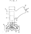
- Fig. 1 is a partly sectioned view of a combined electrolytic-abrasive polisher embodying the present invention;
- Fig. 2 is a partly cutaway front view of a tool employed by the polisher of Fig. 1; and
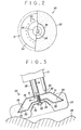
- Fig. 3 is a partly sectioned view showing a polishing operation by the polisher according to the invention.
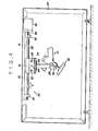
- Fig. 4 is a partly cutaway front view of an automatic electrolytic-abrasive polishing apparatus according to the invention;
- Fig. 5 is a partly cutaway side view of the apparatus of Fig. 4;
- Fig. 6 is a schematic side view of an automatic two-dimensional feed mechanism mounting thereon the polisher of Fig. I;
- Fig. 7 is a schematic front view of major components of the automatic feed mechanism; and
- Fig. 8 is a sectional view taken on line A-A of Fig. 7.
- Shown in the drawings is a polisher according to the invention, which is adapted for use as a combined electrolytic-abrasive polisher. More particularly, the electrolytic-
abrasive polisher 10 shown in Fig. 1 includes a pistol-shaped housing 1 accommodating arotational drive motor 12 and areducer 13 coupled with the output side of the motor to rotate aspindle 14 which is protruded from the housing 11 and has atool 20 attached to the fore end thereof. - As shown particularly in Figs. 1 and 2, the
tool 20 which functions as an electrode in case of electrolytic polishing is constituted by atool base 21 substantially of a disk-like shape and a visco-elastic polishing member 22 attached to the surface of the tool base. - The
tool base 21 includes a disk-likefront plate 24 to be attached to the fore end of thespindle 14, and arear plate 25 which is integrally joined to thefront plate 21 at the peripheral edges thereof to form a liquid pool around and on the back side of thefront plate 24. Thefront plate 24 is centrally provided with arecess 29 to receive therein a head portion of ascrew 28 which fastens thetool base 21 to thespindle 14, and with a multitude ofliquid outlet holes 30 at positions slightly inward of its peripheral edges. Therear plate 25 is formed with a liquid supply opening 31 centrally around thespindle 14, and a slidingcontact surface 32 around the opening 31 for contact with apower supply shoe 33 which supplies electrolytic current as will be described hereinlater. - The visco-
elastic polishing member 22 which is attached to the surface of thetool base 21 is constituted by a liquid permeable visco-elastic material including sponge-like materials such as foamed polyurethane or other foamed synthetic resins or unwoven nylon fabric, which is in the form suitable for attachment to the surface of thetool base 21. In case where a sponge-like material is employed as in the particular embodiment shown, it is provided with acavity 34 which fits on thetool base 21 and mounted on thespindle 14 by fastening same to the spindle together with thetool base 21 by ascrew 28 through adoubling plate 35. In case the visco-elastic polishing member 22 consists of unwoven nylon fabric or the like, its peripheral portions can be fixed to the surface of thetool base 21 by an adhesive or other suitable means and fastened to thespindle 14 through thedoubling plate 35. - The visco-
elastic polishing member 22 may hold abrasive grains dispersedly on its surface or in its entire body. In such a case, abrasive grains of alumina or the like may be fixedly bonded on an unwoven nylon fabric sheet or the like by the use of a synthetic resin bond which is mixed with the abrasive grains. Alternatively, instead of fixing abrasive grains in the just-mentioned manner, loose abrasive grains may be supported in meshes of unwoven fabric. - A multitude of
liquid outlet holes 30 are formed in thefront plate 24 at positions slightly inward of the peripheral edges of thetool base 21 for the purpose of forming apool 26 of the polishing liquid or electrolyte in peripheral portions of thetool base 21, storing the liquid temporarily therein to feed same stably through a large number ofliquid outlet holes 30. Accordingly, while thetool 20 is rotated, the liquid which flows out continuously through theliquid outlet holes 30 is fed to the contacting area between the visco-elastic polishing member 22 and a work around the peripheral portions of thetool 20 under the influence of centrifugal force. In addition, since thetool 20 has a high liquid holding capacity, it is possible to feed the liquid stably not only to a horizontally disposed curved surface but also to almost vertically disposed curved surface. - A
liquid feed pipe 38 which supplies the polishing liquid or electrolyte to polishing areas in the peripheral portions of thetool 20 has itsinlet end 40 opened into one end of the housing 11 and itsoutlet end 41 opened into thetool base 21 through theliquid supply opening 31 which is formed centrally in therear plate 25 around thespindle 14. In this manner, the polishing liquid or electrolyte is simply poured into the liquid pool which is open to the atmosphere, so that it is possible to simplify the equipments for feeding the liquid under pressure. For example, the liquid can be fed to the polisher without resorting to a pump, simply by locating a liquid reservoir at a slightly higher position that of the polisher. - In place of or in addition to the abrasive grains which are carried by the visco-
elastic polishing member 22, free abrasive grains may be admixed into the polishing liquid or electrolyte which is supplied through theliquid feed pipe 38. Especially in case of a polishing operation using fine grains, it is advantageous to use such free abrasive grains which can be uniformly distributed over the entire surface of the visco-elastic polishing member 22. - In case of a polishing operation using abrasive gains alone without supplying current for electrolysis, the liquid which is supplied through the
liquid feed pipe 38 serves to cool the polishing portions and to discharge the fine particles of the stock which is removed by polishing, performing the intended functions by the use of a relatively small amount of liquid similarly to electrolytic polishing. - A
power supply terminal 43 is provided at one end of the housing 11 to supply electrolytic current to thetool 20 through thepower supply shoe 33 and the slidingsurface 32 which is in contact with theshoe 33, and connectible to a power source (not shown) to conduct current across the workpiece andtool 20 serving as positive and negative electrodes, respectively. - Indicated at 44 is a switch member which is manipulatable to actuate the
rotational drive 12. - The above-described electrolytic-abrasive polisher can be used as a portable machine which is lightly pressed by hand against a surface of a workpiece which need polishing, or it is mounted on a carriage which is freely movable in a horizontal plate to perform the polishing operation. As illustrated in Fig. 3, in order to polish a free curved surface of a
work 45, current of several amperes is passed across thetool electrode 20 and work 45 at a voltage of several to some ten volts, while supplying thereto an aqueous solution of NaNO3 or KN03 through the liquid feed pipe and rotating thetool electrode 20 by therotational drive 12, with the peripheral portions of the visco-elastic polishing member 22 on thetool electrode 20 held in pressed contact with the free curved surface of theworkpiece 45. - In a case where the
tool electrode 20 has a diameter of about 12-cm, it can give a mirror finish even to a work surface containing a certain degree of undula- .tions, since the peripheral portions of the visco-elastic polishing member 22 are suitably deformed into a shape which fits the surface profile of the workpiece when pressed thereagainst at a rotational speed of about several hundreds r.p.m. In this instance, the pressure which is imposed by thetool 20 on raised portions of the contacting surface of theworkpiece 45 is naturally greater than the pressure imposed on lower surface portions, so that the amount of stock removal by the abrasive becomes greater on the raised surface portions. However, since relatively large raised and depressed surface portions are finished substantially to the same degree of roughness, works can be polished efficiently in a case where accuracy in shape is not severe. It suffices to supply the electrolyte at a flow rate of one litre per minute or less. - The combined electrolytic-abrasive polishing can be suitably applied to polishing of free curved surfaces of various metallic products, particularly to surface polishing of stainless steels or the like.
- Illustrated in Figs. 4 to 8 is an automatic polishing machine utilizing the above-described electrolytic-
abrasive polisher 10. As seen in Figs. 4 and 5, this automatic polishing machine includes amachine frame 50 formed by joining angles which are extended along the respective edges of a rectangular parallelepiped, and a two-dimensionalautomatic feed mechanism 53 is mounted on asupport plate 51 which is in turn mounted on top of themachine frame 50. - The
automatic feed mechanism 53, which moves thepolisher head 10 on acarriage 54 freely in perpendicularly intersecting X and Y directions in a horizontal plane, in cludes paired parallelX-direction guide rods 58 between a pair ofsupport members base plate 55 which is fixed to thesupport plate 51. Afeed screw 60 which is rotationally driven by amotor 58 on thesupport plate 55 is rotatably supported also in thesupport members direction carriage 61 in which theguide rods 58 are slidably inserted to guide the movements of thecarriage 61 in X-direction. Accordingly, upon rotating thefeed screw 60 by themotor 59, theX-direction carriage 61 is moved in X-direction under guidance of theguide rods 58. - Further, slidably inserted in the
X-direction carriage 61 are a pair of Y-direction guide rods 63 and afeed screw 64 which are disposed perpendicular to theX-direction guide rods 58. These guiderods 63 are fixedly mounted betweensupport members carriage 54, and thefeed screw 64 is rotatably supported on-the twosupport members feed screw 64 coupled with amotor 68 mounted on thecarriage 54. Accordingly, upon rotating themotor 68, thecarriage 54 is moved in Y-direction relative to theX-direction carriage 61. - The
motors feed mechanism 53 are connected to a controller, not shown, which controls the operation of these two motors to move thecarriage 54 along predetermined paths of movements and which may utilize one of known controllers as used in two-dimensional feed mechanisms of this sort. - As shown particularly in Figs. 6 to 8, a pair of
guides carriage 54 to support thepolisher head 10 slidably in a direction Z vertical to planes X and Y. These guides 70 and 71 are provided withslots - On the other hand, the
polisher 10 is fixed in aholer 74 which is arranged to hold thepolisher 10 in-between a pair ofsplit members support rods support members split members plate 81 linking thesplit members bolts Slide members support rods split members butterfly nuts slide members slots angle indicator plate 89 with a dial of angle of inclination is fixed on theslide member 85, and apointer plate 90 is fitted in thesupport rod 77 in such a manner as to permit its axial sliding movement while blocking its rotational movement. - Consequently, as illustrated in Fig. 4, if the
butterfly nuts polisher 10 in a suitable inclined position, thesquare slide members polisher 10 can be slided freely in the direction Z in the tilted state since theslide members slots guides angle indicator plate 89, on which thepointer plate 90 registers. In order to reduce the resistance of sliding movement of theslide members slots - In the automatic polishing machine of the above-described construction, a workpiece is set in the
machine frame 50 and thepolisher 10 is tilted suitably depending upon the surface profile of the workpiece, and, in the tilted state, peripheral portions of the visco-elastic polishing member are contacted with the work surface as explained hereinbefore in connection with Fig. 3. At the same time, thecarriage 54 is moved two-dimensionally by the controller along courses which have been preset beforehand according to the surface profile of the work. - In the automatic polishing operation, it is necessary to maintain the angle of inclination of the spindle of the tool within the afore-mentioned appropriate range relative to the work surface in contact with the visco-elastic polishing member. If this is not possible, the polishing operation is once stopped, and resumed after changing the angle of inclination.
- While the
polisher 10 is two-dimensionally moved by the automatic two-dimensional feed mechanism 53, the visco-elastic polishing member is pressed on the work surface by the weight of thepolisher 10 itself. Therefore, it is necessary for thepolisher 10 to have a suitable weight for this purpose. In a case where the weight of thepolisher 10 itself is insufficient, a spring may be interposed between thecarriage 54 andpolisher 10. The provision of such a spring is also necessary to secure the required pressing force of the visco-elastic member when polishing a vertical surface of a workpiece by apolisher head 10 on the above-mentioned horizontal type automatic polishing machine. - The force with which the visco-elastic polishing member is pressed on the work surface is as small as several tens kPa, and the chipping action of abrasive grains is far weaker than that of the conventional solid grinder namely, not stronger than mere scratching action on the work surface, so that the major portion of the frictional resistance in the polishing operation is considered to take place between the visco-elastic polishing member and the work surface. Since the head pressing force is light as mentioned hereinbefore, the
polisher head 10 can be automatically moved in Z-direction along the surface profile of a work simply by feeding thepolisher head 10 two-dimensionally by the above-described two-dimensional feed mechanism 53. - Although the automatic polishing machine has been shown as having a hand-operating polisher head of Figs. 1 to 3 fixedly mounted on a
holder 74, it may of course be replaced by a polisher head which is constructed exclusively for the automatic polishing machine. - Although the polisher of the invention has been described in connection with an electrolytic-abrasive polishing machine in the foregoing description, it is possible to omit the components for electrolysis and to use the polisher for mirror surface polishing by abrasive grains alone.
Claims (9)
Applications Claiming Priority (2)
| Application Number | Priority Date | Filing Date | Title |
|---|---|---|---|
| JP60125/85 | 1985-03-25 | ||
| JP60060125A JPS61219526A (en) | 1985-03-25 | 1985-03-25 | Electrode tool for electrolytic and abrasive grain composite polishing device |
Publications (3)
| Publication Number | Publication Date |
|---|---|
| EP0196832A2 true EP0196832A2 (en) | 1986-10-08 |
| EP0196832A3 EP0196832A3 (en) | 1988-05-25 |
| EP0196832B1 EP0196832B1 (en) | 1992-05-20 |
Family
ID=13133097
Family Applications (1)
| Application Number | Title | Priority Date | Filing Date |
|---|---|---|---|
| EP86302062A Expired - Lifetime EP0196832B1 (en) | 1985-03-25 | 1986-03-20 | Mirror finish polisher |
Country Status (5)
| Country | Link |
|---|---|
| EP (1) | EP0196832B1 (en) |
| JP (1) | JPS61219526A (en) |
| KR (1) | KR930004543B1 (en) |
| DE (1) | DE3685360D1 (en) |
| HK (1) | HK16595A (en) |
Cited By (16)
| Publication number | Priority date | Publication date | Assignee | Title |
|---|---|---|---|---|
| EP0379361A1 (en) * | 1989-01-18 | 1990-07-25 | Minnesota Mining And Manufacturing Company | Compounding, glazing or polishing pad |
| US5185964A (en) * | 1989-01-18 | 1993-02-16 | Minnesota Mining And Manufacturing Company | Compounding, glazing or polishing pad |
| EP0628382A1 (en) * | 1993-06-04 | 1994-12-14 | Tadao Kodate | Plastic flexible grinding stone |
| US5389032A (en) * | 1993-04-07 | 1995-02-14 | Minnesota Mining And Manufacturing Company | Abrasive article |
| US5396737A (en) * | 1989-01-18 | 1995-03-14 | Minnesota Mining And Manufacturing Company | Compounding, glazing or polishing pad |
| US5716259A (en) * | 1995-11-01 | 1998-02-10 | Miller; Paul David | Surface polishing method and system |
| WO1998055266A1 (en) * | 1997-06-06 | 1998-12-10 | Engelbert Gmeilbauer | Grinding tool, specially for hand-held oscillating devices |
| US6081959A (en) * | 1996-07-01 | 2000-07-04 | Umbrell; Richard | Buffer centering system |
| US6105197A (en) * | 1998-04-14 | 2000-08-22 | Umbrell; Richard T. | Centering system for buffing pad |
| US6241579B1 (en) | 1997-01-10 | 2001-06-05 | Auto Wax Company, Inc. | Surface polishing applicator system and method |
| US6298518B1 (en) | 1998-04-14 | 2001-10-09 | Richard T. Umbrell | Heat dissipating buffing pad |
| WO2012136376A1 (en) * | 2011-04-06 | 2012-10-11 | Deckel Maho Seebach Gmbh | Device for polishing workpiece surfaces |
| US8992644B2 (en) | 2009-04-01 | 2015-03-31 | Joybond Co., Ltd. | Plastic soft composition for polishing and for surface protective material application |
| CN108714824A (en) * | 2018-06-08 | 2018-10-30 | 辽宁科技大学 | A kind of portable magnetic derusting polishing machine and application method |
| CN111531450A (en) * | 2020-06-19 | 2020-08-14 | 湘潭大学 | Take chip-breaker carbide blade chemical mechanical polishing equipment |
| CN117226696A (en) * | 2023-11-14 | 2023-12-15 | 山西富兴通重型环锻件有限公司 | Flange plate polishing device |
Families Citing this family (2)
| Publication number | Priority date | Publication date | Assignee | Title |
|---|---|---|---|---|
| CN110587460A (en) * | 2019-09-10 | 2019-12-20 | 合肥嘉东光学股份有限公司 | Angle-adjustable plane inclined shaft refiner |
| CN117067077B (en) * | 2023-09-27 | 2024-04-02 | 晟高新能源(江苏)有限公司 | Edge trimming device of photovoltaic module |
Citations (10)
| Publication number | Priority date | Publication date | Assignee | Title |
|---|---|---|---|---|
| FR420551A (en) * | 1909-09-20 | 1911-02-02 | August Puggel | Polishing or varnishing machine for woodworking |
| US2309819A (en) * | 1941-04-18 | 1943-02-02 | Carborundum Co | Art of grinding and polishing glass and apparatus therefor |
| US3089287A (en) * | 1961-07-11 | 1963-05-14 | Lukens Steel Co | Slab grinder, hydraulic counterbalance and lift control |
| FR1374441A (en) * | 1962-08-15 | 1964-10-09 | Micromatic Hone Corp | Improvements in processes and devices for electrolytic rectification |
| GB1122483A (en) * | 1965-01-27 | 1968-08-07 | Bliss E W Co | Tilted spindle grinder |
| US3619401A (en) * | 1968-04-03 | 1971-11-09 | Norton Co | Apparatus for electrodeposition |
| US3706650A (en) * | 1971-03-26 | 1972-12-19 | Norton Co | Contour activating device |
| US3779887A (en) * | 1972-03-14 | 1973-12-18 | Sifco Ind Inc | Vibratory applicator for electroplating solutions |
| US4140598A (en) * | 1976-06-03 | 1979-02-20 | Hitachi Shipbuilding & Engineering Co., Ltd. | Mirror finishing |
| JPS58206317A (en) * | 1982-05-25 | 1983-12-01 | Hitachi Zosen Corp | Electrode tool for electrolytic complex mirror machining |
Family Cites Families (2)
| Publication number | Priority date | Publication date | Assignee | Title |
|---|---|---|---|---|
| JPS4913992U (en) * | 1972-05-06 | 1974-02-05 | ||
| JPS5914113U (en) * | 1982-07-14 | 1984-01-28 | アルプス電気株式会社 | magnetic head |
-
1985
- 1985-03-25 JP JP60060125A patent/JPS61219526A/en active Granted
-
1986
- 1986-03-20 DE DE8686302062T patent/DE3685360D1/en not_active Expired - Fee Related
- 1986-03-20 EP EP86302062A patent/EP0196832B1/en not_active Expired - Lifetime
- 1986-03-24 KR KR1019860002162A patent/KR930004543B1/en not_active IP Right Cessation
-
1995
- 1995-02-06 HK HK16595A patent/HK16595A/en not_active IP Right Cessation
Patent Citations (10)
| Publication number | Priority date | Publication date | Assignee | Title |
|---|---|---|---|---|
| FR420551A (en) * | 1909-09-20 | 1911-02-02 | August Puggel | Polishing or varnishing machine for woodworking |
| US2309819A (en) * | 1941-04-18 | 1943-02-02 | Carborundum Co | Art of grinding and polishing glass and apparatus therefor |
| US3089287A (en) * | 1961-07-11 | 1963-05-14 | Lukens Steel Co | Slab grinder, hydraulic counterbalance and lift control |
| FR1374441A (en) * | 1962-08-15 | 1964-10-09 | Micromatic Hone Corp | Improvements in processes and devices for electrolytic rectification |
| GB1122483A (en) * | 1965-01-27 | 1968-08-07 | Bliss E W Co | Tilted spindle grinder |
| US3619401A (en) * | 1968-04-03 | 1971-11-09 | Norton Co | Apparatus for electrodeposition |
| US3706650A (en) * | 1971-03-26 | 1972-12-19 | Norton Co | Contour activating device |
| US3779887A (en) * | 1972-03-14 | 1973-12-18 | Sifco Ind Inc | Vibratory applicator for electroplating solutions |
| US4140598A (en) * | 1976-06-03 | 1979-02-20 | Hitachi Shipbuilding & Engineering Co., Ltd. | Mirror finishing |
| JPS58206317A (en) * | 1982-05-25 | 1983-12-01 | Hitachi Zosen Corp | Electrode tool for electrolytic complex mirror machining |
Non-Patent Citations (1)
| Title |
|---|
| PATENT ABSTRACTS OF JAPAN, vol. 8, no. 54 (M-282)[1491], 10th March 1984; & JP-A-58 206 317 (HITACHI ZOSEN K.K.) 01-12-1983 * |
Cited By (25)
| Publication number | Priority date | Publication date | Assignee | Title |
|---|---|---|---|---|
| US5185964A (en) * | 1989-01-18 | 1993-02-16 | Minnesota Mining And Manufacturing Company | Compounding, glazing or polishing pad |
| EP0379361A1 (en) * | 1989-01-18 | 1990-07-25 | Minnesota Mining And Manufacturing Company | Compounding, glazing or polishing pad |
| US5396737A (en) * | 1989-01-18 | 1995-03-14 | Minnesota Mining And Manufacturing Company | Compounding, glazing or polishing pad |
| USRE35021E (en) * | 1989-01-18 | 1995-08-22 | Minnesota Mining And Manufacturing Company | Compounding, glazing or polishing pad |
| US5727993A (en) * | 1993-04-06 | 1998-03-17 | Joybond Co., Inc. | Plastic flexible grinding stone |
| US5389032A (en) * | 1993-04-07 | 1995-02-14 | Minnesota Mining And Manufacturing Company | Abrasive article |
| US5476416A (en) * | 1993-06-04 | 1995-12-19 | Kodate; Tadao | Plastic flexible grinding stone |
| EP0628382A1 (en) * | 1993-06-04 | 1994-12-14 | Tadao Kodate | Plastic flexible grinding stone |
| US5716259A (en) * | 1995-11-01 | 1998-02-10 | Miller; Paul David | Surface polishing method and system |
| US5928064A (en) * | 1995-11-01 | 1999-07-27 | Auto Wax Company, Inc. | Surface polishing method and system |
| US6081959A (en) * | 1996-07-01 | 2000-07-04 | Umbrell; Richard | Buffer centering system |
| US6547643B1 (en) | 1997-01-10 | 2003-04-15 | Auto Wax Company, Inc. | Surface polishing applicator system and method |
| US6241579B1 (en) | 1997-01-10 | 2001-06-05 | Auto Wax Company, Inc. | Surface polishing applicator system and method |
| WO1998055266A1 (en) * | 1997-06-06 | 1998-12-10 | Engelbert Gmeilbauer | Grinding tool, specially for hand-held oscillating devices |
| US6105197A (en) * | 1998-04-14 | 2000-08-22 | Umbrell; Richard T. | Centering system for buffing pad |
| US6298518B1 (en) | 1998-04-14 | 2001-10-09 | Richard T. Umbrell | Heat dissipating buffing pad |
| US8992644B2 (en) | 2009-04-01 | 2015-03-31 | Joybond Co., Ltd. | Plastic soft composition for polishing and for surface protective material application |
| WO2012136376A1 (en) * | 2011-04-06 | 2012-10-11 | Deckel Maho Seebach Gmbh | Device for polishing workpiece surfaces |
| CN103648720A (en) * | 2011-04-06 | 2014-03-19 | 德克尔·马霍·泽巴赫有限责任公司 | Device for polishing workpiece surfaces |
| US9623536B2 (en) | 2011-04-06 | 2017-04-18 | Deckel Maho Seebach Gmbh | Device for polishing workpiece surfaces |
| CN108714824A (en) * | 2018-06-08 | 2018-10-30 | 辽宁科技大学 | A kind of portable magnetic derusting polishing machine and application method |
| CN108714824B (en) * | 2018-06-08 | 2023-06-02 | 辽宁科技大学 | Portable magnetic rust removal polishing machine and use method |
| CN111531450A (en) * | 2020-06-19 | 2020-08-14 | 湘潭大学 | Take chip-breaker carbide blade chemical mechanical polishing equipment |
| CN117226696A (en) * | 2023-11-14 | 2023-12-15 | 山西富兴通重型环锻件有限公司 | Flange plate polishing device |
| CN117226696B (en) * | 2023-11-14 | 2024-01-23 | 山西富兴通重型环锻件有限公司 | Flange plate polishing device |
Also Published As
| Publication number | Publication date |
|---|---|
| HK16595A (en) | 1995-02-10 |
| KR860007060A (en) | 1986-10-06 |
| JPS61219526A (en) | 1986-09-29 |
| DE3685360T (en) | 1992-06-25 |
| EP0196832A3 (en) | 1988-05-25 |
| EP0196832B1 (en) | 1992-05-20 |
| KR930004543B1 (en) | 1993-06-01 |
| DE3685360D1 (en) | 1992-06-25 |
| JPH0420726B2 (en) | 1992-04-06 |
Similar Documents
| Publication | Publication Date | Title |
|---|---|---|
| EP0196832A2 (en) | Mirror finish polisher | |
| US4609450A (en) | Combined electrolytic-abrasive polishing apparatus | |
| CN211540720U (en) | Robot polisher station | |
| CN110814974A (en) | Robot polisher station | |
| CN215788622U (en) | Grinding machine | |
| CN214642583U (en) | High-precision grinding machine | |
| CN212145908U (en) | Spiral curved surface polishing machine | |
| CN208468031U (en) | A kind of auto-measuring formula side polishing line | |
| CN114043325A (en) | Carbon-carbon composite material rotary body robot polishing workstation | |
| JPS62228364A (en) | Line system continuous feeding specular face polishing device | |
| US6969298B2 (en) | Grinding machine, in particular centerless cylindrical grinding machine | |
| CN218856382U (en) | Special grinding machine for nozzle taper | |
| KR200414569Y1 (en) | Auto-grinder | |
| CN216608428U (en) | Six numerical control polisher | |
| JPS61219525A (en) | Electrolytic and abrasive grain composite automatic polishing device | |
| CN218874891U (en) | Polishing device | |
| CN216463975U (en) | Grinding wheel dressing device | |
| CN218427324U (en) | Quick high-precision grinding mechanism for pen core | |
| CN114770321B (en) | Axial combined type positioning device for machining of numerical control grinding machine | |
| CN213795591U (en) | Automatic knife grinder | |
| CN215700690U (en) | High-precision polishing machine | |
| CN219444656U (en) | Grinding wheel processing grinding machine | |
| CN212665626U (en) | Double-servo bearing inner diameter grinding device | |
| CN214445128U (en) | Grinding device for hardware machining | |
| CN217394583U (en) | Multi-axis processing device for processing diamonds |
Legal Events
| Date | Code | Title | Description |
|---|---|---|---|
| PUAI | Public reference made under article 153(3) epc to a published international application that has entered the european phase |
Free format text: ORIGINAL CODE: 0009012 |
|
| AK | Designated contracting states |
Kind code of ref document: A2 Designated state(s): DE FR GB |
|
| PUAL | Search report despatched |
Free format text: ORIGINAL CODE: 0009013 |
|
| AK | Designated contracting states |
Kind code of ref document: A3 Designated state(s): DE FR GB |
|
| 17P | Request for examination filed |
Effective date: 19881122 |
|
| 17Q | First examination report despatched |
Effective date: 19900504 |
|
| GRAA | (expected) grant |
Free format text: ORIGINAL CODE: 0009210 |
|
| AK | Designated contracting states |
Kind code of ref document: B1 Designated state(s): DE FR GB |
|
| PG25 | Lapsed in a contracting state [announced via postgrant information from national office to epo] |
Ref country code: FR Effective date: 19920520 |
|
| REF | Corresponds to: |
Ref document number: 3685360 Country of ref document: DE Date of ref document: 19920625 |
|
| EN | Fr: translation not filed | ||
| PLBE | No opposition filed within time limit |
Free format text: ORIGINAL CODE: 0009261 |
|
| STAA | Information on the status of an ep patent application or granted ep patent |
Free format text: STATUS: NO OPPOSITION FILED WITHIN TIME LIMIT |
|
| 26N | No opposition filed | ||
| REG | Reference to a national code |
Ref country code: GB Ref legal event code: 732E |
|
| PGFP | Annual fee paid to national office [announced via postgrant information from national office to epo] |
Ref country code: GB Payment date: 19980311 Year of fee payment: 13 |
|
| PGFP | Annual fee paid to national office [announced via postgrant information from national office to epo] |
Ref country code: DE Payment date: 19980327 Year of fee payment: 13 |
|
| PG25 | Lapsed in a contracting state [announced via postgrant information from national office to epo] |
Ref country code: GB Free format text: LAPSE BECAUSE OF NON-PAYMENT OF DUE FEES Effective date: 19990320 |
|
| GBPC | Gb: european patent ceased through non-payment of renewal fee |
Effective date: 19990320 |
|
| PG25 | Lapsed in a contracting state [announced via postgrant information from national office to epo] |
Ref country code: DE Free format text: LAPSE BECAUSE OF NON-PAYMENT OF DUE FEES Effective date: 20000101 |