EP0195591A2 - Formstabile, offenendige, thermoplastische, rohrförmige Gegenstände - Google Patents
Formstabile, offenendige, thermoplastische, rohrförmige Gegenstände Download PDFInfo
- Publication number
- EP0195591A2 EP0195591A2 EP86301789A EP86301789A EP0195591A2 EP 0195591 A2 EP0195591 A2 EP 0195591A2 EP 86301789 A EP86301789 A EP 86301789A EP 86301789 A EP86301789 A EP 86301789A EP 0195591 A2 EP0195591 A2 EP 0195591A2
- Authority
- EP
- European Patent Office
- Prior art keywords
- mandrel
- mould
- tube
- temperature
- contact
- Prior art date
- Legal status (The legal status is an assumption and is not a legal conclusion. Google has not performed a legal analysis and makes no representation as to the accuracy of the status listed.)
- Granted
Links
Images


Classifications
-
- B—PERFORMING OPERATIONS; TRANSPORTING
- B29—WORKING OF PLASTICS; WORKING OF SUBSTANCES IN A PLASTIC STATE IN GENERAL
- B29C—SHAPING OR JOINING OF PLASTICS; SHAPING OF MATERIAL IN A PLASTIC STATE, NOT OTHERWISE PROVIDED FOR; AFTER-TREATMENT OF THE SHAPED PRODUCTS, e.g. REPAIRING
- B29C49/00—Blow-moulding, i.e. blowing a preform or parison to a desired shape within a mould; Apparatus therefor
- B29C49/42—Component parts, details or accessories; Auxiliary operations
- B29C49/48—Moulds
- B29C49/4823—Moulds with incorporated heating or cooling means
-
- B—PERFORMING OPERATIONS; TRANSPORTING
- B29—WORKING OF PLASTICS; WORKING OF SUBSTANCES IN A PLASTIC STATE IN GENERAL
- B29C—SHAPING OR JOINING OF PLASTICS; SHAPING OF MATERIAL IN A PLASTIC STATE, NOT OTHERWISE PROVIDED FOR; AFTER-TREATMENT OF THE SHAPED PRODUCTS, e.g. REPAIRING
- B29C71/00—After-treatment of articles without altering their shape; Apparatus therefor
- B29C71/02—Thermal after-treatment
-
- B—PERFORMING OPERATIONS; TRANSPORTING
- B29—WORKING OF PLASTICS; WORKING OF SUBSTANCES IN A PLASTIC STATE IN GENERAL
- B29K—INDEXING SCHEME ASSOCIATED WITH SUBCLASSES B29B, B29C OR B29D, RELATING TO MOULDING MATERIALS OR TO MATERIALS FOR MOULDS, REINFORCEMENTS, FILLERS OR PREFORMED PARTS, e.g. INSERTS
- B29K2067/00—Use of polyesters or derivatives thereof, as moulding material
-
- B—PERFORMING OPERATIONS; TRANSPORTING
- B29—WORKING OF PLASTICS; WORKING OF SUBSTANCES IN A PLASTIC STATE IN GENERAL
- B29K—INDEXING SCHEME ASSOCIATED WITH SUBCLASSES B29B, B29C OR B29D, RELATING TO MOULDING MATERIALS OR TO MATERIALS FOR MOULDS, REINFORCEMENTS, FILLERS OR PREFORMED PARTS, e.g. INSERTS
- B29K2995/00—Properties of moulding materials, reinforcements, fillers, preformed parts or moulds
- B29K2995/0012—Properties of moulding materials, reinforcements, fillers, preformed parts or moulds having particular thermal properties
- B29K2995/0017—Heat stable
-
- B—PERFORMING OPERATIONS; TRANSPORTING
- B29—WORKING OF PLASTICS; WORKING OF SUBSTANCES IN A PLASTIC STATE IN GENERAL
- B29L—INDEXING SCHEME ASSOCIATED WITH SUBCLASS B29C, RELATING TO PARTICULAR ARTICLES
- B29L2023/00—Tubular articles
- B29L2023/22—Tubes or pipes, i.e. rigid
-
- Y—GENERAL TAGGING OF NEW TECHNOLOGICAL DEVELOPMENTS; GENERAL TAGGING OF CROSS-SECTIONAL TECHNOLOGIES SPANNING OVER SEVERAL SECTIONS OF THE IPC; TECHNICAL SUBJECTS COVERED BY FORMER USPC CROSS-REFERENCE ART COLLECTIONS [XRACs] AND DIGESTS
- Y10—TECHNICAL SUBJECTS COVERED BY FORMER USPC
- Y10S—TECHNICAL SUBJECTS COVERED BY FORMER USPC CROSS-REFERENCE ART COLLECTIONS [XRACs] AND DIGESTS
- Y10S264/00—Plastic and nonmetallic article shaping or treating: processes
- Y10S264/90—Direct application of fluid pressure differential to shape, reshape, i.e. distort, or sustain an article or preform and heat-setting, i.e. crystallizing of stretched or molecularly oriented portion thereof
Definitions
- the present invention relates to apparatus and methods for making thermoplastic tubular articles, which are open at both ends, which are dimensionally stable up to a specific elevated temperature and which are made from crystailisable polymers, and to the articles made thereby, particularly tubular bodies of saturated linear polyester materials such as polyethylene terephthalate, which are intended for processable food and beverage containers.
- European Patent Application No 82630109.5 (Publication No 008 14 5 1 ) filed by the Goodyear Tire and Rubber Company is concerned with a process and apparatus where the formation, by plug-forming, and heat-treatment of PET tube are combined.
- the heat-treatment is separate from the forming step, with the result that open-ended tubular articles can be produced.
- apparatus for making a thermoplastic tubular article of a crystailisable polymer which is open at both ends and which will be dimensionally stable up to a specific elevated temperature, comprises a mandrel, cooling means for cooling the mandrel to a temperature below the glass transition temperature of the tubular article, a mould having a cavity of complementary shape to that of the mandrel and adapted to surround the mandrel with a small clearance between the mandrel and mould, heating means for heating the mould to a temperature higher than said specific elevated temperature, clamping means for clamping portions adjacent each end of an at least partly biaxially oriented polymer tube disposed between the mandrel and mould, thereby axially restraining said tube, and expansion means for elastically expanding the polymer tube into contact with the mould.
- the mandrel and mould are movable axially relative to one another.
- the mould is additionally pivotable relative to the mandrel.
- the apparatus may further comprise means for applying a vacuum to the mould cavity.
- This alone could provide the expansion means for axially expanding the polymer tube by sucking it into contact with the mould, but in any case it would avoid air entrapment between the polymer tube and mould during tube expansion.
- the mandrel is hollow and has perforations in its surface, the expansion means comprising a conduit for supplying pressurised fluid to the interior of the mandrel.
- This expansion means can be used alone or in conjunction with the vacuum to expand the polymer tube into contact with the mould.
- the mould may comprise a mould wall which is made of an air-permeable materiaf, such as sintered bronze, to minimise air entrapment between the expanding PET tube and the mould wall.
- a mould wall which is made of an air-permeable materiaf, such as sintered bronze, to minimise air entrapment between the expanding PET tube and the mould wall.
- Such a mould may be used satisfactorily in conjunction with the embodiment in which the PET tube is expanded solely by or with the aid of a vacuum applied between the PET tube and mould wall.
- the clamping means may comprise, adjacent each end of the mandrel, an inflatable toroid of a resilient material such as rubber, adapted to co-operate when inflated, with respective surfaces on the mould to clamp said portions of the tube adjacent its ends between each toroid and the respective surface on the mould
- An alternative clamping means comprises a pair of split-ring clamps, each having a fixed half-ring and a movable half-ring reciprocable relative to the fixed half-ring, whereby the polymer tube end portions can be squeezed between each clamp and the mandrel.
- the cooling means may comprise, where the mandrel is hollow, a helical conduit of a material of high thermal conductivity in thermal contact with the internal surface of the hollow mandrel, the conduit being served by supply and return means for cooling fluid, such as tap water.
- the heating means for the mould may comprise band heaters wrapped around the external surface of the mould.
- thermoplastic tubu- far article which is open at both ends and which will be dimensionally stable up to a specific elevated temperature
- a method of making a thermoplastic tubu- far article comprising the steps of disposing an at least partly biaxially oriented polymer tube, open at both ends and made of a crystailisable polymer, between a cooled mandrel and a heated mould, so that the mandrel is inside the tube and the mould surrounds and is spaced from the tube, the mould being heated to a temperature higher than said specific elevated temperature and the mandrel being maintained at a temperature below the glass transition temperature of the polymer, clamping portions of the tube adjacent both its ends so that the tube is axially restrained, elastically expanding the tube into contact with the mould, maintaining the tube in contact with the mould for a time sufficient to ensure the required degree of dimensional stability, allowing the tube to shrink back into contact with the mandrel which restrains the tube from further radial shrinkage, the tube remaining in contact with the man
- the heat-setting temperature at which the mould is suitably maintained is a temperature in the range of from 150°C to 230°C.
- the - mandrel is cooled to a temperature suitably below 80°C, by a cooling fluid such as tap water.
- the polymer tube is urged into contact with the mould at a pressure of at least 3.4 bars.
- the illustrated embodiments of the invention are particularly, but not exclusively, concerned with the production of tubular bodies made of polyethylene terephthalate (PET) for thermally processable food containers which have end closures seamed to the ends of the body.
- PET polyethylene terephthalate
- the tubular bodies, open at both ends, are made from tubes of at least partly biaxially oriented PET which may be produced by the process disclosed in our prior British Patent application No. 8037137 (publication No. 2089276A).
- the containers will be able to withstand hot-filling, pasteurisation or sterilisation processes at temperatures of from 60°C to 120°C without unacceptable shrinkage, it is necessary to carry out a heat-setting treatment on the oriented PET tube.
- the container bodies must have sufficient dimensional stability in order that the end closures may be matched precisely to give gas-tight seams and in order that the seams are not over-stressed through subsequent shrinkage. These requirements are particularly important when the containers are for food or beverages, as the risk of contamination through damaged seams must be substantially eliminated.
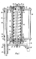
- the apparatus generally comprises a fixed external mould 12 adapted to receive therein a mandrel 10 mounted for axial movement relative to the mould 12 in a vertical direction.
- the mandrel 10 comprises a hollow, cylindrical mandrel body 14 closed at each end by respective end blocks 16, 18.
- the end blocks 16,18 are held in the ends of the mandrel body 1 4 by means of a central, axially extending bolt 20.
- O-rings 22 disposed between the end blocks and the respective end portions of the mandrel body ensure an air-tight seal.
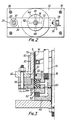
- the mandrel 10 is mounted on a support bracket 24 by means of the central bolt 20, and this support bracket 24 ( Figures 1 and 2) is provided with a sleeve 25, housing a pair of spaced bearings 26 and with a roller 28.
- the mandrel 10 is slidably mounted for axial movement relative to the mould 12, so that it can be received in the mould, as shown in Figure 1, or retracted therefrom ( Figure 4).
- the mould 12 comprises a mould wall 30, which, in this instance, is cylindrical and is of a diameter only slightly larger than that of the mandrel body 14.
- the mould wall 30 can be made of sintered bronze, which renders the wall air-permeable. The clearance between the mandrel body 14 and the mould wall 30 is important and will be discussed in greater detail below.
- the mould 12 further comprises a cage-like structure ' ( Figures 1 and 2) which supports the mould wall 30 and on which the mandrel 10 is mounted for both axial displacement and swinging movement relative to the mould 12.
- This structure comprises a lower plate 32 an an upper plate 34, each having a substantially centrally disposed aperture 33 in which is located a respective end portion of the mould wall 30, the plates 32, 34 being rigidly interconnected adjacent their corners by four struts 36, which hold the plates at a fixed spacing.
- a vertical bearing shaft 37 extends between the plates, projects beyond the lower plate 32, and is held by grub screws 38 in a pair of collars 39, fastened one each to the plates 32, 34.
- the mandrel body 14 and the mould wall 30 are respectively provided with cooling means 40 and heating means 50 so that, during use of the apparatus, the mould wall 30 can be maintained at a predetermined elevated temperature, whilst the mandrel body 14 will be maintained at a temperature below the glass transition temperature of the polymer.
- the cooling means 40 comprises a helical copper conduit, of square cross-section, brazed to the internal surface of the hollow mandrel body 14. Cooling fluid, such as tap water, is supplied to and returned from the conduit 40 respectively by means of an inlet pipe (not shown) and an outlet pipe 42 housed within the hollow mandrel body 14 and both opening into the end block 16 of the mandrel.
- a disc 44 is mounted on the central bolt 20 between the end block 16 and the support bracket 24 and contains an inlet port 46 and an outlet port 48 respectively communicating with the inlet and outlet pipes for the cooling fluid.
- the heating means 50 for the mould wall 30 comprises three conventional band heaters wrapped around the mould wall and thermostatically controlled to maintain the mould wall at said predetermined elevated temperature.
- clamping means 52 for the apparatus.
- a PET tube 5 open at both its ends, is introduced between the mandrel body 14 and mould wall 30 as will be explained below.
- the ends of the tube 5 must be axially restrained. This is achieved by clamping the tube at both its ends and, in this instance, the clamping means 52 comprises, for each end of the PET tube, an inflatable tyre 54, 56 of a resilient material, such as rubber, located one in each of the end blocks 1 6, 18.
- Each tyre 54 , 56 has the form of a hollow toroid open along its inner circumference towards a wall 58 formed by the circumference of a portion of reduced cross-section of the end block 16, 18 which houses the tyre.
- the tyre 52 is held laterally in the end block 16 by the disc 44, while tyre 54 is held in the end block 18 by a washer 59 captive on the central bolt 20.
- Both the tyres 54, 56 are supplied with compressed air through a supply bore 60 which passes through the end block 16 and communicates with a compressed air inlet port 62 in the disc 44 of the mandrel 10.
- the bore 60 supplies the tyre 5 4 directly and branches to a longitudinal pipe 61 extending through the hollow mandrel body 14 for supplying air to the other tyre 56.
- a pressurised fluid such as compressed air
- Facing the external circumference of each tyre is a circular internal surface 63 of a respective collar 64 bolted at 66 to each of the upper and lower plates 32, 34 of the cage for the mould 12.
- the tyres inflate they urge an end portion of the PET tube 5 into contact with the respective opposing surface 63 of the collar 64 on the mould 12.
- the tube 5 is thereby clamped at both of its ends.
- a suitable material for the tyres is silicon rubber as it presents low friction to the tubular article when it is finally stripped from the mandrel 10.
- the mandrel body 14 is provided with a plurality of axially and circumferentially spaced perforations 70.
- the cavity within the hollow mandrel body 14 is adapted to be supplied with compressed air through a port 72 in the disc 44, which port communicates with a bore 74 in the end block 16.
- Air supplied to the interior of the mandrel body will pass out through the perforations 70 to form an air cushion between the mandrel and the PET tube.
- This air bearing provided by the air escaping through perforations 70 in the mandrel body 14 performs two functions. Firstly, it enables a PET tube 5 to be expanded elastically into contact with the heated mould 12 for the heat-setting process to take place while the PET tube is in contact with the mould wall 30. Secondly, it enables the tubular article to be stripped from the mandrel body 14 after it has been formed.
- a vacuum line which provides a vacuum between the mould wall 30 and a PET tube 5 positioned between the mandrel and mould.
- the mandrel body 14 is not provided with perforations 70 or a compressed air supply to its interior and the expansion of the PET tube is achieved solely by means of the vacuum applied between the PET tube and the mould wall 30.
- the clearance between the mandrel body 14 and mould wall 30 has already been referred to. More particularly, the radial clearance between the mandrel body 14 and the mould wall 30 should accommodate the thickness of the PET tube 5 with the remaining radial clearance between PET tube and mould wall 30 being within the elastic limit of the PET tube, so that expansion of the PET tube 5 into contact with the mould wall 30 is entirely elastic, and plastic deformation of the PET tube during expansion is avoided.
- the radial clearance between mandrel body 14 and internal surface of mould wall 30 would be 0.9 mm, i.e. 0.475 mm radial clearance between the PET tube once slipped onto the mandrel. This is within the elastic limit of the PET tube.
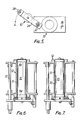
- the mandrel 10 is then swung back into alignment with the mould and moved axially up into the mould 12 until the mandrel 10 and PET tube 5 are received within the mould cavity. Compressed air is then supplied to the port 62 in disc 44 to inflate the tyres 54 and 56, thereby clamping the PET tube 5 against the mould 12 by means of the tyres 54, 56 of the mandrel 10 ( Figures 3 and 6). The PET tube 5 is thereby restrained axially against subsequent shrinkage during the heat-setting process.
- Compressed air is now supplied to the interior of the mandrel and passes through perforations 70 to expand the PET tube elastically into contact with the mould wall 30 - ( Figure 7).
- Air entrapment between the expanding PET tube 5 and the mould wall 30 is avoided by providing an at least partial vacuum between the PET tube 5 and mould wall (as referred to above) and/or by any residual air escaping into the voids within the sintered bronze material of the mould wall 30.
- the pressure is maintained within the hollow mandrel, to hold the PET tube 5 in contact with the mould wall 30 for sufficient time to ensure the required degree of heat-setting.
- the air pressure is then released from the interior of the mandrel and, due to residual shrinkage of the PET tube, the tube 5 shrinks back onto the mandrel 10. It is the mandrel which restrains the PET tube from further radial shrinkage.
- the tube 5 is left in contact with the mandrel until its temperature is reduced to below the glass transition temperature of the polymer material of the tube 5.
- the tyres 54, 56 are then allowed to deflate, releasing the clamp on the PET tube.
- the mandrel 10 is then retracted from the mould 12 back into the position of Figure 4, and swung out of the way as shown in Figure 5.
- the tubular article thus formed is then stripped from the mandrel 10 by introducing compressed air once more into of the mandrel, the air passing out through the mandrel's perforations 70 to separate the tubular article from the mandrel.
- the mould 12 is maintained at the desired temperature for performing the heat-treatment by operation of the band heaters 50, whilst the mandrel 10 is permanently cooled.
- the mould wall 30 is maintained at a heat-setting temperature of up to 230°C and, with the mould wall at this temperature, the heat-setting period during which the tube 5 must be held in contact with the mould wall 30 is of the order of 5 seconds. This is a rapid heat-treatment compared with prior art process.
- the mandrel is positively cooled, typically to below 80°C.
- the pressure urging tube 5 into contact should be at least 3. 4 bars. This will be the resultant pressure of the internal pressure supplied from the hollow mandrel and the vacuum applied between the mould wall 30 and the PET tube.
- the mandrel does not swing relative to the mould when introducing a PET tube 5 onto the mandrel or stripping the tubular article therefrom. Instead, the mandrel remains axially aligned therewith but is retracted to a position further from the mould than is shown in Figure 4 to a position where the tube 5 can be introduced into a position in axial alignment with, and positioned between, the mandrel and mould.
- the mandrel is then advanced towards the mould until it is inserted with the polymer tube 5, and further advancement of the mandrel carries the PET tube into the mould.
- the formed tubular article is removed by the mandrel withdrawing from the mould and carrying the tubular article with it, which article. then being air stripped from the mandrel.
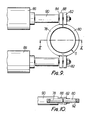
- FIGS 8 to 10 illustrate an alternative embodiment of clamping means.
- clamping means 52 comprising an inflatable resilient tyre 54 and collar 64 gripping the PET tube ends
- the PET tube end portions which project beyond the mould wall 30 are grippable by a respective split-ring clamp 76.
- Each of the two clamps 76 comprises two half-rings, or yokes, one 78 being fixed relative to the mould 12 and the other yoke 80 being adapted to reciprocate toward and away from the fixed yoke.
- the movable yoke 80 is mounted, via a pair of integral ears 82 on a pair of piston rods 8 4 , which are driven to reciprocate along their axes by means of respective fluid pressure cylinders, g.g. air cylinders 86.
- the piston rods 84 pass with clearance through ears on the fixed yoke 78, which is maintained at a fixed separation from the air cylinders by means of spacers 90 slipped over the piston rods 84.
- the yokes 78,80 initially are apart from one another in their "open position" during loading of'a PET tube 5 into the mould.
- the clamps 7 6 are operted by actuating the air cylinders 86 to squeeze the movable yokes 80 towards their respective fixed yokes 78.
- the end portions of the PET tube 5 are thus urged by the clamps 76 against the mandrel within the tube 5.
- the leading edges 92 of the yokes 78,80 i.e. that edge of the yoke first encountered by the mandrel carrying the PET tube 5 up into the mould 12, are chamfered to facilitate insertion of the mandrel and PET tube through the clamps 76 in their "open" position.
- each iris ring clamping the PET tube 5 externally at either end, each iris ring comprising say six to eight separate leaves, each leaf having point contact with the PET tube.
- the illustrated embodiments show the mould and mandrel as having a circular cross-section, clearly it would be possible for the mould and mandrel to have other cross-sections, for instance polygonal, so long as the mould and mandrel were of complementary shape and so long as the mandrel and mould can still have axial relative movement
Landscapes
- Physics & Mathematics (AREA)
- Thermal Sciences (AREA)
- Engineering & Computer Science (AREA)
- Manufacturing & Machinery (AREA)
- Mechanical Engineering (AREA)
- Blow-Moulding Or Thermoforming Of Plastics Or The Like (AREA)
- Materials For Medical Uses (AREA)
- Processing And Handling Of Plastics And Other Materials For Molding In General (AREA)
- Shaping By String And By Release Of Stress In Plastics And The Like (AREA)
- Shaping Of Tube Ends By Bending Or Straightening (AREA)
- Moulds For Moulding Plastics Or The Like (AREA)
- Extrusion Moulding Of Plastics Or The Like (AREA)
Priority Applications (1)
| Application Number | Priority Date | Filing Date | Title |
|---|---|---|---|
| AT86301789T ATE55938T1 (de) | 1985-03-18 | 1986-03-12 | Formstabile, offenendige, thermoplastische, rohrfoermige gegenstaende. |
Applications Claiming Priority (2)
| Application Number | Priority Date | Filing Date | Title |
|---|---|---|---|
| GB8506932 | 1985-03-18 | ||
| GB08506932A GB2172540B (en) | 1985-03-18 | 1985-03-18 | Making dimensionally stable thermoplastic open-ended tubular articles |
Publications (3)
| Publication Number | Publication Date |
|---|---|
| EP0195591A2 true EP0195591A2 (de) | 1986-09-24 |
| EP0195591A3 EP0195591A3 (en) | 1988-10-19 |
| EP0195591B1 EP0195591B1 (de) | 1990-08-29 |
Family
ID=10576166
Family Applications (1)
| Application Number | Title | Priority Date | Filing Date |
|---|---|---|---|
| EP86301789A Expired - Lifetime EP0195591B1 (de) | 1985-03-18 | 1986-03-12 | Formstabile, offenendige, thermoplastische, rohrförmige Gegenstände |
Country Status (7)
| Country | Link |
|---|---|
| US (1) | US4711624A (de) |
| EP (1) | EP0195591B1 (de) |
| JP (1) | JPH0622891B2 (de) |
| AT (1) | ATE55938T1 (de) |
| CA (1) | CA1250721A (de) |
| DE (1) | DE3673670D1 (de) |
| GB (1) | GB2172540B (de) |
Cited By (7)
| Publication number | Priority date | Publication date | Assignee | Title |
|---|---|---|---|---|
| FR2608096A1 (fr) * | 1986-12-15 | 1988-06-17 | Solomat Sa | Procede et installation d'extrusion d'un produit en forme de film, de plaque, de tube, de tige ou de fil |
| EP0434276A1 (de) * | 1989-12-15 | 1991-06-26 | CarnaudMetalbox plc | Thermofixieren von rohrförmigen, thermoplastischen Artikeln |
| EP0439892A3 (en) * | 1990-01-12 | 1991-11-13 | Kingston Technologies, Inc. | Amorphous memory polymer alignment device |
| EP0379091A3 (de) * | 1989-01-18 | 1991-12-18 | AG für Maschinen- und Werkzeugbau | Verfahren und Vorrichtung zur Wärmebehandlung thermogeformter Gegenstände |
| WO1994008772A1 (de) * | 1992-10-21 | 1994-04-28 | Helfried Schnallinger | Verfahren zum herstellen von formteilen aus im warmen zustand formbaren kunststoffen |
| EP1204445A4 (de) * | 1999-07-07 | 2002-11-20 | Schmalbach Lubeca | Kristallisationsmaschine |
| RU2454327C2 (ru) * | 2009-11-24 | 2012-06-27 | Общество С Ограниченной Ответственностью "Сезар" | Установка для изготовления пустотелых изделий |
Families Citing this family (11)
| Publication number | Priority date | Publication date | Assignee | Title |
|---|---|---|---|---|
| IT1197797B (it) * | 1986-07-31 | 1988-12-06 | Luigi Bocchi | Metodo di produzione di contenitore in materilaie termoplastico in particolare da fogli di polietilentereftalato laminato amorfo termoformato e reso cristallino e termoresistente per rapido accostamento a temperatura di transazione su stampo di formatura ed estrazione immediata con controstampo freddo ed aspirante e recipienti con esso prodotti |
| US5472660A (en) * | 1989-03-08 | 1995-12-05 | Fortex, Inc. | Method for the manufacture of shaped products of biaxially oriented polymeric material |
| US6093364A (en) * | 1989-03-08 | 2000-07-25 | Fortex, Inc. | Method for producing a biaxially oriented open-ended container |
| US5328655A (en) * | 1989-03-08 | 1994-07-12 | Fortex, Inc. | Method and apparatus for the manufacture of shaped products of biaxially oriented polymeric material |
| US5251424A (en) * | 1991-01-11 | 1993-10-12 | American National Can Company | Method of packaging products in plastic containers |
| CA2078032C (en) † | 1991-09-12 | 2001-09-04 | Ketan P. Muni | Inflatable member having elastic expansion with limited range |
| FR2706876B1 (de) * | 1993-06-21 | 1995-10-27 | Sidel Sa | |
| US7108826B2 (en) * | 1994-03-02 | 2006-09-19 | Boston Scientific Scimed, Inc. | High compliance, high strength catheter balloons useful for treatment of gastrointestinal lesions |
| US6268026B1 (en) | 1997-10-20 | 2001-07-31 | Hoechst Celanese Corporation | Multilayer laminate formed from a substantially stretched non-molten wholly aromatic liquid crystalline polymer and non-liquid crystalline polyester and method for forming same |
| US6312772B1 (en) | 1997-10-20 | 2001-11-06 | Hoechst Celanese Corporation | Multilayer laminate formed from a substantially stretched non-molten wholly aromatic liquid crystalline polymer and non-polyester thermoplastic polymer |
| US6426128B1 (en) | 1998-01-06 | 2002-07-30 | Hna Holdings, Inc. | Co-processable multi-layer laminates for forming high strength, haze-free, transparent articles and methods of producing same |
Family Cites Families (14)
| Publication number | Priority date | Publication date | Assignee | Title |
|---|---|---|---|---|
| AT220354B (de) * | 1956-12-28 | 1962-03-26 | Resistoflex Corp | Verfahren zur Wärmebehandlung eines Rohres aus Polytetrafluoräthylen od. dgl. und Kern zur Ausübung des Verfahrens |
| LU35737A1 (de) * | 1957-01-30 | |||
| US3182355A (en) * | 1963-05-06 | 1965-05-11 | Anaconda Wire & Cable Co | Tube stretching apparatus |
| US4005968A (en) * | 1975-05-19 | 1977-02-01 | Phillips Petroleum Company | Pipe end reforming apparatus |
| IT1117968B (it) * | 1977-06-21 | 1986-02-24 | Sica Spa | Dispositivo per la formazione della sede per guarnizione negli innesti a manicotto dei tubi in plastica formato da doppio anello elastico corazzato a espansione pneumatica e controllo meccanico delle dimensioni esterne |
| SE423981B (sv) * | 1979-06-11 | 1982-06-21 | Plm Ab | Forfarande och anordning for astadkommande av orienterade materialpartier vid framstellning av rorformad preform av termoplastmaterial |
| US4511322A (en) * | 1979-06-11 | 1985-04-16 | Plm Aktiebolag | Apparatus for the manufacture of a cup-like article from polyethylene terephthalate or similar material |
| US4277231A (en) * | 1979-09-21 | 1981-07-07 | Gordon John H | Method and apparatus for pressure forming pipe bells |
| SE429317B (sv) * | 1980-05-29 | 1983-08-29 | Plm Ab | Sett att astadkomma ett element av polyetylentereftalat eller dermed liknande termoplastmaterial jemte anordning herfor |
| GB2089276B (en) * | 1980-11-19 | 1984-09-05 | Metal Box Co Ltd | Thermoplastics tubular articles |
| US4388356A (en) * | 1981-11-16 | 1983-06-14 | The Goodyear Tire & Rubber Company | Heat setting a thermoformed PET article utilizing a male plug as a constraint |
| GB2138349B (en) * | 1983-04-22 | 1987-06-03 | Metal Box Plc | Dimensionally stable thermoplastic tubular articles |
| JPS6036130A (ja) * | 1983-08-08 | 1985-02-25 | Mitsubishi Heavy Ind Ltd | プラスチックパイプの熱固定方法 |
| US4545951A (en) * | 1984-07-30 | 1985-10-08 | Gordon John H | Method and apparatus for belling pipe ends |
-
1985
- 1985-03-18 GB GB08506932A patent/GB2172540B/en not_active Expired
-
1986
- 1986-03-07 US US06/837,533 patent/US4711624A/en not_active Expired - Fee Related
- 1986-03-11 CA CA000503813A patent/CA1250721A/en not_active Expired
- 1986-03-12 EP EP86301789A patent/EP0195591B1/de not_active Expired - Lifetime
- 1986-03-12 AT AT86301789T patent/ATE55938T1/de not_active IP Right Cessation
- 1986-03-12 DE DE8686301789T patent/DE3673670D1/de not_active Expired - Lifetime
- 1986-03-18 JP JP61060485A patent/JPH0622891B2/ja not_active Expired - Lifetime
Cited By (10)
| Publication number | Priority date | Publication date | Assignee | Title |
|---|---|---|---|---|
| FR2608096A1 (fr) * | 1986-12-15 | 1988-06-17 | Solomat Sa | Procede et installation d'extrusion d'un produit en forme de film, de plaque, de tube, de tige ou de fil |
| WO1988004606A1 (fr) * | 1986-12-15 | 1988-06-30 | Solomat Partners L.P. | Procede et installation d'extrusion d'un produit en forme de film, de plaque, de tube, de tige ou de fil |
| EP0274317A3 (en) * | 1986-12-15 | 1988-07-27 | Solomat S.A. Societe Dite: | Process and device for extruding a product in the form of a film, plate, tube, bar or thread |
| EP0379091A3 (de) * | 1989-01-18 | 1991-12-18 | AG für Maschinen- und Werkzeugbau | Verfahren und Vorrichtung zur Wärmebehandlung thermogeformter Gegenstände |
| EP0434276A1 (de) * | 1989-12-15 | 1991-06-26 | CarnaudMetalbox plc | Thermofixieren von rohrförmigen, thermoplastischen Artikeln |
| EP0439892A3 (en) * | 1990-01-12 | 1991-11-13 | Kingston Technologies, Inc. | Amorphous memory polymer alignment device |
| WO1994008772A1 (de) * | 1992-10-21 | 1994-04-28 | Helfried Schnallinger | Verfahren zum herstellen von formteilen aus im warmen zustand formbaren kunststoffen |
| US5554332A (en) * | 1992-10-21 | 1996-09-10 | Schnallinger; Helfried | Process of manufacturing shaped elements from synthetic thermopolastics |
| EP1204445A4 (de) * | 1999-07-07 | 2002-11-20 | Schmalbach Lubeca | Kristallisationsmaschine |
| RU2454327C2 (ru) * | 2009-11-24 | 2012-06-27 | Общество С Ограниченной Ответственностью "Сезар" | Установка для изготовления пустотелых изделий |
Also Published As
| Publication number | Publication date |
|---|---|
| JPH0622891B2 (ja) | 1994-03-30 |
| GB2172540B (en) | 1988-12-21 |
| CA1250721A (en) | 1989-03-07 |
| GB8506932D0 (en) | 1985-04-24 |
| GB2172540A (en) | 1986-09-24 |
| EP0195591B1 (de) | 1990-08-29 |
| EP0195591A3 (en) | 1988-10-19 |
| ATE55938T1 (de) | 1990-09-15 |
| DE3673670D1 (de) | 1990-10-04 |
| US4711624A (en) | 1987-12-08 |
| JPS61229530A (ja) | 1986-10-13 |
Similar Documents
| Publication | Publication Date | Title |
|---|---|---|
| EP0195591B1 (de) | Formstabile, offenendige, thermoplastische, rohrförmige Gegenstände | |
| US4587075A (en) | Method and apparatus for making dimensionally stable thermoplastic tubular articles | |
| US8100688B2 (en) | Device for blow molding containers | |
| GB2062533A (en) | Blow moulding method | |
| US4097570A (en) | Method for making plastic articles | |
| EP0153342B1 (de) | Verfahren und vorrichtung zur herstellung von rohrförmigen gegenständen aus biaxial orientiertem kunststoff | |
| CA2105976C (en) | Method for producing heat-recoverable articles and apparatus for expanding/shrinking articles | |
| JPH07309303A (ja) | プラスチックチューブ状コンテナの開放端の内面加熱装置 | |
| EP0653286B1 (de) | Verfahren und Vorrichtung zum Transportieren von Kunststoffen in geschmolzen Zustand | |
| USH671H (en) | Process for forming thermoplastic parts especially large structural parts of high viscosity resin replicating mold surface | |
| EP1044783B1 (de) | Verfahren zur herstellung eines axial orientierten kunststoffrohres und so hergestelltes rohr. | |
| US4907958A (en) | Apparatus for flanging tubular polymer articles | |
| USRE25624E (en) | Method of forming plastic containers | |
| JP2024507838A (ja) | 機械的性能が高められた細いピペット | |
| KR101387304B1 (ko) | 분자구조상 바이-오리엔트된 플라스틱 파이프 제조 장치 및 그 방법 | |
| JPS5736628A (en) | Method and apparatus for molding pipelike substance | |
| CA1270452A (en) | Dimensionally stable thermoplastic tubular articles | |
| KR100292582B1 (ko) | 폴리에틸렌파이프에확관부를형성하기위한방법및그장치 | |
| JP2592670B2 (ja) | ポリエステルボトルの製造法 | |
| US4323535A (en) | Manufacture of thermoplastics pipe | |
| JPH04261824A (ja) | 熱可塑性チューブラ物品の熱硬化方法およびその装置 | |
| CN210211351U (zh) | 热缩管内压扩张模具及其构成的扩张装置 | |
| JPH08156080A (ja) | プラスチックボトルの製造方法及び装置並びに口栓部保持用のマンドレル | |
| JPS591225A (ja) | ブロ−成形品を熱処理する方法 | |
| JPS591223A (ja) | ブロ−成形法 |
Legal Events
| Date | Code | Title | Description |
|---|---|---|---|
| PUAI | Public reference made under article 153(3) epc to a published international application that has entered the european phase |
Free format text: ORIGINAL CODE: 0009012 |
|
| 17P | Request for examination filed |
Effective date: 19860402 |
|
| AK | Designated contracting states |
Kind code of ref document: A2 Designated state(s): AT BE CH DE FR GB IT LI LU NL SE |
|
| PUAL | Search report despatched |
Free format text: ORIGINAL CODE: 0009013 |
|
| AK | Designated contracting states |
Kind code of ref document: A3 Designated state(s): AT BE CH DE FR GB IT LI LU NL SE |
|
| RAP1 | Party data changed (applicant data changed or rights of an application transferred) |
Owner name: MB GROUP PLC |
|
| 17Q | First examination report despatched |
Effective date: 19890629 |
|
| RAP1 | Party data changed (applicant data changed or rights of an application transferred) |
Owner name: CMB PACKAGING (UK) LIMITED |
|
| GRAA | (expected) grant |
Free format text: ORIGINAL CODE: 0009210 |
|
| RAP1 | Party data changed (applicant data changed or rights of an application transferred) |
Owner name: CMB FOODCAN PLC |
|
| AK | Designated contracting states |
Kind code of ref document: B1 Designated state(s): AT BE CH DE FR IT LI LU NL SE |
|
| PG25 | Lapsed in a contracting state [announced via postgrant information from national office to epo] |
Ref country code: CH Effective date: 19900829 Ref country code: IT Free format text: LAPSE BECAUSE OF FAILURE TO SUBMIT A TRANSLATION OF THE DESCRIPTION OR TO PAY THE FEE WITHIN THE PRE;WARNING: LAPSES OF ITALIAN PATENTS WITH EFFECTIVE DATE BEFORE 2007 MAY HAVE OCCURRED AT ANY TIME BEFORE 2007. THE CORRECT EFFECTIVE DATE MAY BE DIFFERENT FROM THE ONE RECORDED.SCRIBED TIME-LIMIT Effective date: 19900829 Ref country code: LI Effective date: 19900829 Ref country code: SE Free format text: THE PATENT HAS BEEN ANNULLED BY A DECISION OF A NATIONAL AUTHORITY Effective date: 19900829 Ref country code: AT Effective date: 19900829 |
|
| REF | Corresponds to: |
Ref document number: 55938 Country of ref document: AT Date of ref document: 19900915 Kind code of ref document: T |
|
| REF | Corresponds to: |
Ref document number: 3673670 Country of ref document: DE Date of ref document: 19901004 |
|
| ET | Fr: translation filed | ||
| REG | Reference to a national code |
Ref country code: CH Ref legal event code: PL |
|
| PG25 | Lapsed in a contracting state [announced via postgrant information from national office to epo] |
Ref country code: LU Free format text: LAPSE BECAUSE OF NON-PAYMENT OF DUE FEES Effective date: 19910331 Ref country code: BE Effective date: 19910331 |
|
| PLBE | No opposition filed within time limit |
Free format text: ORIGINAL CODE: 0009261 |
|
| STAA | Information on the status of an ep patent application or granted ep patent |
Free format text: STATUS: NO OPPOSITION FILED WITHIN TIME LIMIT |
|
| 26N | No opposition filed | ||
| BERE | Be: lapsed |
Owner name: CMB FOODCAN P.L.C. Effective date: 19910331 |
|
| PG25 | Lapsed in a contracting state [announced via postgrant information from national office to epo] |
Ref country code: NL Effective date: 19911001 |
|
| NLV4 | Nl: lapsed or anulled due to non-payment of the annual fee | ||
| PGFP | Annual fee paid to national office [announced via postgrant information from national office to epo] |
Ref country code: FR Payment date: 19950208 Year of fee payment: 10 |
|
| PGFP | Annual fee paid to national office [announced via postgrant information from national office to epo] |
Ref country code: DE Payment date: 19950217 Year of fee payment: 10 |
|
| PG25 | Lapsed in a contracting state [announced via postgrant information from national office to epo] |
Ref country code: FR Effective date: 19961129 |
|
| PG25 | Lapsed in a contracting state [announced via postgrant information from national office to epo] |
Ref country code: DE Effective date: 19961203 |
|
| REG | Reference to a national code |
Ref country code: FR Ref legal event code: ST |