EP0195399B1 - Method of and apparatus for reducing volume and surface defects in silica optical-fibres - Google Patents
Method of and apparatus for reducing volume and surface defects in silica optical-fibres Download PDFInfo
- Publication number
- EP0195399B1 EP0195399B1 EP86103599A EP86103599A EP0195399B1 EP 0195399 B1 EP0195399 B1 EP 0195399B1 EP 86103599 A EP86103599 A EP 86103599A EP 86103599 A EP86103599 A EP 86103599A EP 0195399 B1 EP0195399 B1 EP 0195399B1
- Authority
- EP
- European Patent Office
- Prior art keywords
- temperature
- fibre
- furnace
- preform
- silica
- Prior art date
- Legal status (The legal status is an assumption and is not a legal conclusion. Google has not performed a legal analysis and makes no representation as to the accuracy of the status listed.)
- Expired
Links
- VYPSYNLAJGMNEJ-UHFFFAOYSA-N Silicium dioxide Chemical compound O=[Si]=O VYPSYNLAJGMNEJ-UHFFFAOYSA-N 0.000 title claims description 27
- 230000007547 defect Effects 0.000 title claims description 17
- 239000000377 silicon dioxide Substances 0.000 title claims description 13
- 238000000034 method Methods 0.000 title claims description 11
- 230000001603 reducing effect Effects 0.000 title claims description 8
- 239000000835 fiber Substances 0.000 claims description 19
- 239000000463 material Substances 0.000 claims description 15
- OKTJSMMVPCPJKN-UHFFFAOYSA-N Carbon Chemical compound [C] OKTJSMMVPCPJKN-UHFFFAOYSA-N 0.000 claims description 13
- 229910052799 carbon Inorganic materials 0.000 claims description 13
- 230000007704 transition Effects 0.000 claims description 10
- 239000011261 inert gas Substances 0.000 claims description 9
- 239000013307 optical fiber Substances 0.000 claims description 7
- 238000001816 cooling Methods 0.000 claims description 6
- 239000011521 glass Substances 0.000 claims description 6
- 230000003287 optical effect Effects 0.000 claims description 6
- 238000006243 chemical reaction Methods 0.000 claims description 5
- 239000004215 Carbon black (E152) Substances 0.000 claims description 4
- 239000007789 gas Substances 0.000 claims description 4
- 229930195733 hydrocarbon Natural products 0.000 claims description 4
- 150000002430 hydrocarbons Chemical class 0.000 claims description 4
- 239000002245 particle Substances 0.000 claims description 3
- 230000008021 deposition Effects 0.000 claims description 2
- 238000002844 melting Methods 0.000 claims description 2
- 230000008018 melting Effects 0.000 claims description 2
- 238000010438 heat treatment Methods 0.000 claims 3
- 238000000354 decomposition reaction Methods 0.000 claims 1
- 238000005979 thermal decomposition reaction Methods 0.000 claims 1
- VNWKTOKETHGBQD-UHFFFAOYSA-N methane Chemical compound C VNWKTOKETHGBQD-UHFFFAOYSA-N 0.000 description 5
- 208000013201 Stress fracture Diseases 0.000 description 3
- 239000011248 coating agent Substances 0.000 description 3
- 238000000576 coating method Methods 0.000 description 3
- 238000004519 manufacturing process Methods 0.000 description 3
- UFHFLCQGNIYNRP-UHFFFAOYSA-N Hydrogen Chemical compound [H][H] UFHFLCQGNIYNRP-UHFFFAOYSA-N 0.000 description 2
- 230000015572 biosynthetic process Effects 0.000 description 2
- 239000003795 chemical substances by application Substances 0.000 description 2
- 150000001875 compounds Chemical class 0.000 description 2
- 238000009792 diffusion process Methods 0.000 description 2
- 239000001257 hydrogen Substances 0.000 description 2
- 229910052739 hydrogen Inorganic materials 0.000 description 2
- 230000008569 process Effects 0.000 description 2
- 230000005855 radiation Effects 0.000 description 2
- 230000009467 reduction Effects 0.000 description 2
- 238000007789 sealing Methods 0.000 description 2
- 235000012239 silicon dioxide Nutrition 0.000 description 2
- LIVNPJMFVYWSIS-UHFFFAOYSA-N silicon monoxide Chemical compound [Si-]#[O+] LIVNPJMFVYWSIS-UHFFFAOYSA-N 0.000 description 2
- MYMOFIZGZYHOMD-UHFFFAOYSA-N Dioxygen Chemical compound O=O MYMOFIZGZYHOMD-UHFFFAOYSA-N 0.000 description 1
- XUIMIQQOPSSXEZ-UHFFFAOYSA-N Silicon Chemical compound [Si] XUIMIQQOPSSXEZ-UHFFFAOYSA-N 0.000 description 1
- 238000010521 absorption reaction Methods 0.000 description 1
- 230000003213 activating effect Effects 0.000 description 1
- 238000013459 approach Methods 0.000 description 1
- QVGXLLKOCUKJST-UHFFFAOYSA-N atomic oxygen Chemical compound [O] QVGXLLKOCUKJST-UHFFFAOYSA-N 0.000 description 1
- 230000005540 biological transmission Effects 0.000 description 1
- 125000004432 carbon atom Chemical group C* 0.000 description 1
- 239000000919 ceramic Substances 0.000 description 1
- 229910010293 ceramic material Inorganic materials 0.000 description 1
- 239000003638 chemical reducing agent Substances 0.000 description 1
- 238000004891 communication Methods 0.000 description 1
- 230000001419 dependent effect Effects 0.000 description 1
- 230000000694 effects Effects 0.000 description 1
- 239000012467 final product Substances 0.000 description 1
- 150000002431 hydrogen Chemical class 0.000 description 1
- 230000006872 improvement Effects 0.000 description 1
- 239000013081 microcrystal Substances 0.000 description 1
- 239000001301 oxygen Substances 0.000 description 1
- 229910052760 oxygen Inorganic materials 0.000 description 1
- 230000009257 reactivity Effects 0.000 description 1
- 239000011347 resin Substances 0.000 description 1
- 229920005989 resin Polymers 0.000 description 1
- 229910052710 silicon Inorganic materials 0.000 description 1
- 239000010703 silicon Substances 0.000 description 1
- 229910010271 silicon carbide Inorganic materials 0.000 description 1
- 239000000126 substance Substances 0.000 description 1
- 230000000930 thermomechanical effect Effects 0.000 description 1
Images
Classifications
-
- C—CHEMISTRY; METALLURGY
- C03—GLASS; MINERAL OR SLAG WOOL
- C03C—CHEMICAL COMPOSITION OF GLASSES, GLAZES OR VITREOUS ENAMELS; SURFACE TREATMENT OF GLASS; SURFACE TREATMENT OF FIBRES OR FILAMENTS MADE FROM GLASS, MINERALS OR SLAGS; JOINING GLASS TO GLASS OR OTHER MATERIALS
- C03C25/00—Surface treatment of fibres or filaments made from glass, minerals or slags
- C03C25/10—Coating
- C03C25/12—General methods of coating; Devices therefor
- C03C25/22—Deposition from the vapour phase
- C03C25/223—Deposition from the vapour phase by chemical vapour deposition or pyrolysis
-
- C—CHEMISTRY; METALLURGY
- C03—GLASS; MINERAL OR SLAG WOOL
- C03B—MANUFACTURE, SHAPING, OR SUPPLEMENTARY PROCESSES
- C03B37/00—Manufacture or treatment of flakes, fibres, or filaments from softened glass, minerals, or slags
- C03B37/01—Manufacture of glass fibres or filaments
- C03B37/02—Manufacture of glass fibres or filaments by drawing or extruding, e.g. direct drawing of molten glass from nozzles; Cooling fins therefor
- C03B37/025—Manufacture of glass fibres or filaments by drawing or extruding, e.g. direct drawing of molten glass from nozzles; Cooling fins therefor from reheated softened tubes, rods, fibres or filaments, e.g. drawing fibres from preforms
- C03B37/027—Fibres composed of different sorts of glass, e.g. glass optical fibres
- C03B37/02718—Thermal treatment of the fibre during the drawing process, e.g. cooling
-
- C—CHEMISTRY; METALLURGY
- C03—GLASS; MINERAL OR SLAG WOOL
- C03B—MANUFACTURE, SHAPING, OR SUPPLEMENTARY PROCESSES
- C03B37/00—Manufacture or treatment of flakes, fibres, or filaments from softened glass, minerals, or slags
- C03B37/01—Manufacture of glass fibres or filaments
- C03B37/02—Manufacture of glass fibres or filaments by drawing or extruding, e.g. direct drawing of molten glass from nozzles; Cooling fins therefor
- C03B37/025—Manufacture of glass fibres or filaments by drawing or extruding, e.g. direct drawing of molten glass from nozzles; Cooling fins therefor from reheated softened tubes, rods, fibres or filaments, e.g. drawing fibres from preforms
- C03B37/029—Furnaces therefor
-
- C—CHEMISTRY; METALLURGY
- C03—GLASS; MINERAL OR SLAG WOOL
- C03C—CHEMICAL COMPOSITION OF GLASSES, GLAZES OR VITREOUS ENAMELS; SURFACE TREATMENT OF GLASS; SURFACE TREATMENT OF FIBRES OR FILAMENTS MADE FROM GLASS, MINERALS OR SLAGS; JOINING GLASS TO GLASS OR OTHER MATERIALS
- C03C25/00—Surface treatment of fibres or filaments made from glass, minerals or slags
- C03C25/10—Coating
- C03C25/104—Coating to obtain optical fibres
- C03C25/106—Single coatings
- C03C25/1061—Inorganic coatings
-
- C—CHEMISTRY; METALLURGY
- C03—GLASS; MINERAL OR SLAG WOOL
- C03B—MANUFACTURE, SHAPING, OR SUPPLEMENTARY PROCESSES
- C03B2205/00—Fibre drawing or extruding details
- C03B2205/56—Annealing or re-heating the drawn fibre prior to coating
-
- Y—GENERAL TAGGING OF NEW TECHNOLOGICAL DEVELOPMENTS; GENERAL TAGGING OF CROSS-SECTIONAL TECHNOLOGIES SPANNING OVER SEVERAL SECTIONS OF THE IPC; TECHNICAL SUBJECTS COVERED BY FORMER USPC CROSS-REFERENCE ART COLLECTIONS [XRACs] AND DIGESTS
- Y02—TECHNOLOGIES OR APPLICATIONS FOR MITIGATION OR ADAPTATION AGAINST CLIMATE CHANGE
- Y02P—CLIMATE CHANGE MITIGATION TECHNOLOGIES IN THE PRODUCTION OR PROCESSING OF GOODS
- Y02P40/00—Technologies relating to the processing of minerals
- Y02P40/50—Glass production, e.g. reusing waste heat during processing or shaping
- Y02P40/57—Improving the yield, e-g- reduction of reject rates
Definitions
- the present invention concerns methods of manufacturing transmission media for telecommunications systems using light radiations and more particularly it relates to a method of and an apparatus for reducing surface and volume defects in silica optical fibres.
- the defects consist in superficial micro-fractures of different depth which according to their type and density affect more or less seriously the mechanical properties of resistance to traction and dynamic fatigue of the fibre.
- the layer of carbon particles under nascent state, deposited on the upper preform zone thanks to the thermal-gradient presence, is made to diffuse into the silica material by a temperature equal to glass melting temperature and a reaction with silica will take place according to the equation the presence of square brackets meaning a prevailing silica presence in the preform material.
- the deposited carbon layer meets thermal conditions allowing its weak diffusion into the material and besides, since the surface is activited by the reducing atmosphere, it can react with the material giving rise to a mixed compound with greater density than silica.
- the final material has a more compact and uniform structure and presents a more regular surface; as a consequence, its surface properties render it less liable to micro-fractures. Besides, since the whole process is based on diffusion phenomena, the material characteristics vary gradually from the inside towards the outside, thus obtaining a less critical structure from the mechanical point of view.
- drawing temperature is generally very high, as it corresponds to softening temperature of the material; more precisely it is about twice as high as the vitreous transition temperature, which for pure silica is equal to 1100°C.
- the method of the invention provides a passage from softening temperature to ambient temperature through an intermediate step at a temperature slightly higher, for safety purposes, than that of vitreous transition Tg.
- the final product having been frozen under the best conditions for the glass manufacturing, has no volume defects.
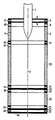
- the figure shows an apparatus for carrying out the method.
- Reference 1 indicates the preform wherefrom optical fibre 2 is drawn.
- Glass softening temperature of about 2000 ° C, is obtained by a furnace 3, equipped with a silica window 4, through which the temperature can be optically read.
- the preform enters the furnace through a pair of disks 5 and 6, with central holes, between which an inert gas e.g. N 2 or Ar, is sent through inlets 7 and 8.
- an inert gas e.g. N 2 or Ar
- Methane (CH 4 ) is injected through inlets 11 and 12; thanks to high temperature present in furnace 3, it decomposes into C 2 and H 2 .
- Nascent state carbon and an atmosphere rich in hydrogen, and consequently with reducing properties, are thus obtained.
- the just-obtained fibre traverses a second furnace 13, capable of ensuring at its inside a slightly higher temperature than vitreous transition temperature, e.g. 1120 ° C. Also this furnace is provided with a window 14, through which fibre diameter can be read and is closed at the bottom by a disk 15 with a central hole. An inert gas is injected through inlets 16 and 17 inside the furnace 13. Said gas is preheated at 1120 ° C and has the task of sealing the gap present between disk 15 and optical fibre 2.
- the fibre After traversing disk 15, the fibre enters a chamber at low temperature, whose value ranges between + 20 and - 50 ° C, delimited by a conditioner 20 and a pair of disks 23 and 26 with central holes.
- a cold inert gas is injected into the chamber through inlets 18 and 19 and is then sucked away through outlets 22 and 21.
- An inert gas is injected also through inlets 24 and 25 with the task of sealing the gap comprised between disk 26 and the fibre.
Landscapes
- Chemical & Material Sciences (AREA)
- Engineering & Computer Science (AREA)
- Life Sciences & Earth Sciences (AREA)
- Organic Chemistry (AREA)
- General Life Sciences & Earth Sciences (AREA)
- Geochemistry & Mineralogy (AREA)
- Materials Engineering (AREA)
- Chemical Kinetics & Catalysis (AREA)
- Manufacturing & Machinery (AREA)
- General Chemical & Material Sciences (AREA)
- Physics & Mathematics (AREA)
- Thermal Sciences (AREA)
- Inorganic Chemistry (AREA)
- Manufacture, Treatment Of Glass Fibers (AREA)
- Glass Compositions (AREA)
- Glass Melting And Manufacturing (AREA)
Applications Claiming Priority (2)
| Application Number | Priority Date | Filing Date | Title |
|---|---|---|---|
| IT6726585 | 1985-03-18 | ||
| IT67265/85A IT1184909B (it) | 1985-03-18 | 1985-03-18 | Procedimento ed apparecchiatura per la riduzione dei difetti di volume e di superficie nelle fibre ottiche in silice |
Publications (2)
| Publication Number | Publication Date |
|---|---|
| EP0195399A1 EP0195399A1 (en) | 1986-09-24 |
| EP0195399B1 true EP0195399B1 (en) | 1989-11-15 |
Family
ID=11300974
Family Applications (1)
| Application Number | Title | Priority Date | Filing Date |
|---|---|---|---|
| EP86103599A Expired EP0195399B1 (en) | 1985-03-18 | 1986-03-17 | Method of and apparatus for reducing volume and surface defects in silica optical-fibres |
Country Status (6)
| Country | Link |
|---|---|
| US (2) | US4659354A (cg-RX-API-DMAC7.html) |
| EP (1) | EP0195399B1 (cg-RX-API-DMAC7.html) |
| JP (1) | JPS61215232A (cg-RX-API-DMAC7.html) |
| CA (1) | CA1274393A (cg-RX-API-DMAC7.html) |
| DE (2) | DE3666945D1 (cg-RX-API-DMAC7.html) |
| IT (1) | IT1184909B (cg-RX-API-DMAC7.html) |
Families Citing this family (29)
| Publication number | Priority date | Publication date | Assignee | Title |
|---|---|---|---|---|
| US5024688A (en) * | 1988-11-30 | 1991-06-18 | Fujikura Ltd. | Method for producing carbon-coated optical fiber |
| CA2004234C (en) * | 1988-12-01 | 1994-04-19 | Keiji Oohashi | Optical fiber production method |
| US5269825A (en) * | 1989-04-28 | 1993-12-14 | Fujikura, Ltd. | Method of manufacturing radiation-resistant optical fiber |
| US5147432A (en) * | 1989-10-19 | 1992-09-15 | At&T Bell Laboratories | Methods of and apparatus for coating optical fibers |
| US5199993A (en) * | 1989-10-19 | 1993-04-06 | At&T Bell Laboratories | Methods of and apparatus for coating optical fibers |
| US5242477A (en) * | 1989-10-19 | 1993-09-07 | At&T Bell Laboratories | Apparatus for coating optical fibers |
| EP0462893B1 (en) * | 1990-06-19 | 1995-04-12 | Fujikura Ltd. | Method for splicing and reinforcing carbon coated optical fibers |
| JP2798486B2 (ja) * | 1990-08-01 | 1998-09-17 | 住友電気工業株式会社 | ハーメチックコート光ファイバの製造方法及び製造装置 |
| DE4028275A1 (de) * | 1990-09-06 | 1992-03-12 | Kabelmetal Electro Gmbh | Verfahren zur herstellung von glasfaser-lichtwellenleitern mit erhoehter zugfestigkeit |
| US5059229A (en) * | 1990-09-24 | 1991-10-22 | Corning Incorporated | Method for producing optical fiber in a hydrogen atmosphere to prevent attenuation |
| US5152817A (en) * | 1991-01-15 | 1992-10-06 | Corning Incorporated | Reactor for coating optical fibers |
| US5346520A (en) * | 1992-09-23 | 1994-09-13 | Corning Incorporated | Apparatus for applying a carbon coating to optical fibers |
| US5755850A (en) * | 1992-09-24 | 1998-05-26 | Iowa State University Research Foundation | Method of making a surgical laser fiber from a monolithic silica titania glass rod |
| DE4339077C2 (de) * | 1993-11-16 | 1997-03-06 | Rheydt Kabelwerk Ag | Verfahren zum Ziehen einer optischen Faser und Vorrichtung zu dessen Durchführung |
| US5868734A (en) * | 1995-11-29 | 1999-02-09 | Iowa State University Research Foundation, Inc. | Methods of using silica-titania clad fibers |
| US6345519B1 (en) * | 1996-10-25 | 2002-02-12 | Corning Incorporated | Method of reducing break sources in drawn fibers by active oxidation of contaminants in a reducing atmosphere |
| CN1247477C (zh) * | 1999-05-27 | 2006-03-29 | 住友电气工业株式会社 | 光纤的制造装置和制造方法 |
| JP2002234751A (ja) * | 2001-01-31 | 2002-08-23 | Fujikura Ltd | 光ファイバ紡糸方法 |
| JP2003114347A (ja) * | 2001-07-30 | 2003-04-18 | Furukawa Electric Co Ltd:The | シングルモード光ファイバ、その製造方法および製造装置 |
| KR100429532B1 (ko) * | 2001-10-22 | 2004-05-03 | 삼성전자주식회사 | 광섬유제조장치의 드로타워 구조 |
| US6789400B2 (en) * | 2001-11-30 | 2004-09-14 | The Boc Group, Inc. | Cap assembly and optical fiber cooling process |
| US20030205066A1 (en) * | 2002-03-25 | 2003-11-06 | Ghani M. Usman | Method and apparatus for efficient cooling of optical fiber during its manufacture |
| US20030200772A1 (en) * | 2002-04-30 | 2003-10-30 | Foster John D. | Methods and apparatus for forming optical fiber |
| KR100545814B1 (ko) * | 2002-08-31 | 2006-01-24 | 엘에스전선 주식회사 | 광섬유 인선 용해로 및 이를 이용한 광섬유 인선방법 |
| US20040107736A1 (en) * | 2002-12-09 | 2004-06-10 | Alcatel | Pure upflow furnace |
| US20070022786A1 (en) * | 2003-04-28 | 2007-02-01 | Foster John D | Methods and apparatus for forming heat treated optical fiber |
| CN101090874B (zh) * | 2004-12-27 | 2011-03-02 | 古河电气工业株式会社 | 玻璃条的制造方法、玻璃条以及玻璃基板 |
| US8074474B2 (en) * | 2007-11-29 | 2011-12-13 | Corning Incorporated | Fiber air turn for low attenuation fiber |
| JP2020528863A (ja) * | 2017-07-25 | 2020-10-01 | メイド イン スペース インコーポレイティッド | 光ファイバを製造するためのシステムおよび方法 |
Family Cites Families (10)
| Publication number | Priority date | Publication date | Assignee | Title |
|---|---|---|---|---|
| US3125428A (en) * | 1964-03-17 | Uethod for coating silica rods | ||
| US4306897A (en) * | 1980-04-16 | 1981-12-22 | International Telephone And Telegraph Corporation | Method of fabricating fatigue resistant optical fibers |
| US4400190A (en) * | 1981-09-28 | 1983-08-23 | Gte Laboratories Incorporated | Graphite element for use in a furnace for drawing optical fiber |
| US4514205A (en) * | 1981-11-05 | 1985-04-30 | Corning Glass Works | Fiber cooling apparatus |
| US4437870A (en) * | 1981-11-05 | 1984-03-20 | Corning Glass Works | Optical waveguide fiber cooler |
| US4440556A (en) * | 1982-06-23 | 1984-04-03 | International Telephone And Telegraph Corporation | Optical fiber drawing using plasma torch |
| JPS59162149A (ja) * | 1983-03-02 | 1984-09-13 | Ushio Inc | 石英ガラスの表面に炭化珪素膜を設ける方法 |
| US4613521A (en) * | 1983-06-30 | 1986-09-23 | At&T Technologies, Inc. | Methods of and apparatus for coating a lightguide fiber |
| DE3340640A1 (de) * | 1983-11-10 | 1985-05-23 | Felten & Guilleaume Energietechnik GmbH, 5000 Köln | Verfahren zur herstellung von siliciumcarbidfasern |
| US4578098A (en) * | 1984-06-15 | 1986-03-25 | At&T Technologies, Inc. | Apparatus for controlling lightguide fiber tension during drawing |
-
1985
- 1985-03-18 IT IT67265/85A patent/IT1184909B/it active
-
1986
- 1986-01-08 US US06/817,025 patent/US4659354A/en not_active Expired - Fee Related
- 1986-03-10 CA CA000503656A patent/CA1274393A/en not_active Expired - Lifetime
- 1986-03-13 JP JP61053817A patent/JPS61215232A/ja active Granted
- 1986-03-17 DE DE8686103599T patent/DE3666945D1/de not_active Expired
- 1986-03-17 EP EP86103599A patent/EP0195399B1/en not_active Expired
- 1986-03-17 DE DE198686103599T patent/DE195399T1/de active Pending
- 1986-11-13 US US06/930,804 patent/US4702759A/en not_active Expired - Fee Related
Also Published As
| Publication number | Publication date |
|---|---|
| US4659354A (en) | 1987-04-21 |
| CA1274393A (en) | 1990-09-25 |
| US4702759A (en) | 1987-10-27 |
| EP0195399A1 (en) | 1986-09-24 |
| DE3666945D1 (en) | 1989-12-21 |
| IT8567265A1 (it) | 1986-09-18 |
| JPH0587455B2 (cg-RX-API-DMAC7.html) | 1993-12-16 |
| JPS61215232A (ja) | 1986-09-25 |
| IT8567265A0 (it) | 1985-03-18 |
| IT1184909B (it) | 1987-10-28 |
| DE195399T1 (de) | 1987-02-05 |
Similar Documents
| Publication | Publication Date | Title |
|---|---|---|
| EP0195399B1 (en) | Method of and apparatus for reducing volume and surface defects in silica optical-fibres | |
| US5320658A (en) | Process of drawing optical fiber | |
| US5000541A (en) | Hermetically sealed optical fibers | |
| JP4290760B2 (ja) | ガラス基板上の被膜形成方法及び被膜付きガラス基板 | |
| EP0308143B1 (en) | Hermetically sealed optical fibers | |
| US5322540A (en) | Method of depositing pyrolyzed films having improved performance and glazing pane coated with the same | |
| EP0374926B1 (en) | Method for producing a carbon-coated optical fiber | |
| CN105636918B (zh) | 制造具有降低的氢敏感度的光纤的包括光纤方向改变的方法 | |
| US5979188A (en) | Method of fabricating a planar waveguide structure | |
| EP0250465A1 (en) | CONTINUOUS VACUUM METALLIZATION PROCESS FOR COATING A GLASS ARTICLE. | |
| EP0472944B1 (en) | Method and apparatus for producing hermetic coated optical fiber | |
| EP0402895A1 (en) | Hermetically coated optical fiber and production of the same | |
| EP0222960B1 (en) | Method and apparatus for the on-line coating of silica based fibers with boron-nitride | |
| JPS5924095B2 (ja) | 単一モ−ド光ファイバ−プレフォ−ムの製造方法 | |
| US4294514A (en) | Light-wave guides and method of producing same | |
| JP2734586B2 (ja) | 光ファイバ素線 | |
| US4116657A (en) | Process for increasing the annealing point of 96% silica glass | |
| JPH02263741A (ja) | カーボンコート光ファイバの製造方法 | |
| JP2727702B2 (ja) | カーボンコート光ファイバの製造方法 | |
| JPH02145462A (ja) | ハーメチックコートフアイバの製造方法 | |
| JPH0587456B2 (cg-RX-API-DMAC7.html) | ||
| EP4543817A1 (en) | Coated glass articles | |
| JPH02243539A (ja) | カーボンコート光ファイバの製造方法 | |
| JPH0437623A (ja) | 光ファイバ母材の製造方法 | |
| JPH0312345A (ja) | ハーメチック被覆光ファイバの製造方法 |
Legal Events
| Date | Code | Title | Description |
|---|---|---|---|
| PUAI | Public reference made under article 153(3) epc to a published international application that has entered the european phase |
Free format text: ORIGINAL CODE: 0009012 |
|
| AK | Designated contracting states |
Kind code of ref document: A1 Designated state(s): DE FR GB NL SE |
|
| 17P | Request for examination filed |
Effective date: 19861023 |
|
| EL | Fr: translation of claims filed | ||
| TCNL | Nl: translation of patent claims filed | ||
| DET | De: translation of patent claims | ||
| 17Q | First examination report despatched |
Effective date: 19870727 |
|
| GRAA | (expected) grant |
Free format text: ORIGINAL CODE: 0009210 |
|
| AK | Designated contracting states |
Kind code of ref document: B1 Designated state(s): DE FR GB NL SE |
|
| REF | Corresponds to: |
Ref document number: 3666945 Country of ref document: DE Date of ref document: 19891221 |
|
| ET | Fr: translation filed | ||
| PLBE | No opposition filed within time limit |
Free format text: ORIGINAL CODE: 0009261 |
|
| STAA | Information on the status of an ep patent application or granted ep patent |
Free format text: STATUS: NO OPPOSITION FILED WITHIN TIME LIMIT |
|
| 26N | No opposition filed | ||
| PGFP | Annual fee paid to national office [announced via postgrant information from national office to epo] |
Ref country code: SE Payment date: 19920212 Year of fee payment: 7 |
|
| PGFP | Annual fee paid to national office [announced via postgrant information from national office to epo] |
Ref country code: GB Payment date: 19920311 Year of fee payment: 7 |
|
| PGFP | Annual fee paid to national office [announced via postgrant information from national office to epo] |
Ref country code: NL Payment date: 19920331 Year of fee payment: 7 Ref country code: FR Payment date: 19920331 Year of fee payment: 7 Ref country code: DE Payment date: 19920331 Year of fee payment: 7 |
|
| PG25 | Lapsed in a contracting state [announced via postgrant information from national office to epo] |
Ref country code: GB Effective date: 19930317 |
|
| PG25 | Lapsed in a contracting state [announced via postgrant information from national office to epo] |
Ref country code: SE Effective date: 19930318 |
|
| PG25 | Lapsed in a contracting state [announced via postgrant information from national office to epo] |
Ref country code: NL Effective date: 19931001 |
|
| NLV4 | Nl: lapsed or anulled due to non-payment of the annual fee | ||
| GBPC | Gb: european patent ceased through non-payment of renewal fee |
Effective date: 19930317 |
|
| PG25 | Lapsed in a contracting state [announced via postgrant information from national office to epo] |
Ref country code: FR Effective date: 19931130 |
|
| PG25 | Lapsed in a contracting state [announced via postgrant information from national office to epo] |
Ref country code: DE Effective date: 19931201 |
|
| REG | Reference to a national code |
Ref country code: FR Ref legal event code: ST |
|
| EUG | Se: european patent has lapsed |
Ref document number: 86103599.6 Effective date: 19931008 |