EP0195357A2 - Farbbildröhre - Google Patents
Farbbildröhre Download PDFInfo
- Publication number
- EP0195357A2 EP0195357A2 EP86103265A EP86103265A EP0195357A2 EP 0195357 A2 EP0195357 A2 EP 0195357A2 EP 86103265 A EP86103265 A EP 86103265A EP 86103265 A EP86103265 A EP 86103265A EP 0195357 A2 EP0195357 A2 EP 0195357A2
- Authority
- EP
- European Patent Office
- Prior art keywords
- mask
- cathode ray
- mask frame
- shadow mask
- tube
- Prior art date
- Legal status (The legal status is an assumption and is not a legal conclusion. Google has not performed a legal analysis and makes no representation as to the accuracy of the status listed.)
- Granted
Links
Images


Classifications
-
- H—ELECTRICITY
- H01—ELECTRIC ELEMENTS
- H01J—ELECTRIC DISCHARGE TUBES OR DISCHARGE LAMPS
- H01J29/00—Details of cathode-ray tubes or of electron-beam tubes of the types covered by group H01J31/00
- H01J29/02—Electrodes; Screens; Mounting, supporting, spacing or insulating thereof
-
- H—ELECTRICITY
- H01—ELECTRIC ELEMENTS
- H01J—ELECTRIC DISCHARGE TUBES OR DISCHARGE LAMPS
- H01J29/00—Details of cathode-ray tubes or of electron-beam tubes of the types covered by group H01J31/00
- H01J29/02—Electrodes; Screens; Mounting, supporting, spacing or insulating thereof
- H01J29/06—Screens for shielding; Masks interposed in the electron stream
- H01J29/07—Shadow masks for colour television tubes
- H01J29/073—Mounting arrangements associated with shadow masks
Definitions
- the present invention relates to a color cathode ray tube and, more particularly, to a structure for supporting a shadow mask on an inner surface of a panel thereof.
- a conventional color cathode ray tube has a vacuum envelope comprising rectangular panel 1, funnel 2, and neck 3.
- Phosphor screen 4 consisting of phosphor stripes for emitting red, green, and blue light rays, upon landing of electron beams thereon, is formed on an inner surface of a faceplate of panel 1.
- So-called in-line electron gun assembly 6 is aligned along the horizontal axis of panel 1, and is arranged in neck 3 so as to emit three electron beams corresponding to the red, green, and blue phosphor stripes.
- a peripheral portion of shadow mask 5 is supported by mask frame 17.
- Shadow mask 5 has a large number of slit apertures aligned in the vertical direction and a large number of vertical arrays aligned in the horizontal direction.
- Frame 17 is fixed at positions near screen 4 through resilient support member 12.
- Electron beams 14 are deflected by external deflection coil 9 located outside funnel 2 and the shadow mask 5 is scanned with the deflected beams. Electron beams 14 pass through the apertures of mask 5 and land on their corresponding phosphor stripes, thereby reproducing a color image. In order to prevent degradation of color purity in the reproduced image, caused by mislanding of electron beams on the phosphor stripes due to an external magnetic field influence such as geomagnetism, magnetic shielding plate a of a ferromagnetic metal is locked inside funnel 2 through frame 7.
- a pitch of the slit apertures of mask 5 must be about 1/3 that of the phosphor stripes. For this reason, the number of effective electron beams 1 4 passing through the slit apertures is normally decreased to 1/3 or less. The remaining electron beams 14 bombard mask 5, often heating it to about 80°C. In particular, in special color cathode ray tubes used for display CRTs in aircraft cockpits, shadow masks are often heated to about 200°C
- Mask 5 is normally made of a 0.2-mm thick thin plate which has, as a major constituent, iron with a relatively large thermal expansion coefficient. The peripheral portion of mask 5 is fixed by a 1.6-mm thick rigid mask frame 7.
- Electron beams 14 bombarding mask 5 heat and expand it, thus changing a gap (to be referred to as a Q value for brevity hereinafter) between screen 4 and mask 5.
- a Q value for brevity hereinafter
- electron beams 14 cannot land accurately on the phosphor stripes, thereby causing mislanding and the subsequent color purity degradation described above.
- mask frame is locked on a panel side wall, i.e., a skirt, through bimetal as a resilient support member. When it is heated, the entire mask is-moved by bimetal toward scxeen 4 so as to substantially maintain the Q value within the allowable range.
- Japanese Patent Publication No. 58-144 Japanese Patent Disclosure No. 53-144252 describes the color cathode ray tube shown in Fig. 2.
- frame 17 of shadow mask 5 is supported by frame support or hook member 12 on the inner surface of panel 1.
- Support 12 is elastic and deformable and has a substantially V-shaped section.
- This prior art also describes that electron beam mislanding caused by dooming can be prevented when an angle e of the V-shaped frame support is half that of the deflection angle of the tube.
- Japanese Patent Publication No. 46-4104 describes a color cathode ray tube with substantially L-shaped resilient support member 12.
- a mask frame is not used and member 12 is directly connected to the peripheral edge of shadow mask 5.
- heat can be directly conducted from the shadow mask to the mask support.
- color cathode ray tubes with a shadow mask of an 36% Ni-Fe alloy i.e., and invar steel member
- the invar steet member has a thermal expansion coefficient as small as 1/10 of that of the conventional cold-rolled steel plate mainly made of Fe and greatly reduces thermal expansion of the shadow mask.
- the mask frame is preferably also constituted by an invar steel member, in order to prevent a conventional drawback (e.g., thermal deformation of the shadow mask) caused by a difference between thermal expansion coefficients of the shadow mask and the mask frame during heat treatment
- a conventional drawback e.g., thermal deformation of the shadow mask
- characteristics of the color cathode ray tube are improved by the use of an invar steel member as a shadow mask while a cold-rolled steel plate mainly made of Fe is used as the mask frame, in order to minimize an increase in total cost of the color cathode ray tube.
- a color cathode ray tube using such an invar steel member however, the degradation of color purity cannot be sufficiently prevented (to be described in detail later).
- a color cathode ray tube comprising a vacuum envelope with an axis and including a panel section, a funnel section and a neck section, said panel section being composed of a faceplate, a front view shape of which is substantially rectangular and which has an inner surface, and a skirt with a peripheral inner surface extending from a peripheral edge of said faceplate, said funnel section being contiguous to said skirt of said panel
- said neck section being contiguous to said funnel section, a phosphor screen formed on said inner surface of said faceplate, an electron gun assembly, arranged in said neck section, for emitting electron beams to be landed on said phosphor screen, a shadow mask arranged in said panel section to oppose said phosphor screen and having a large number of apertures for allowing passage of electron beams therethrough, said shadow mask being made of a metal with a thermal expansion coefficient am, a mask frame for suspending and supporting said shadow mask, said mask frame being made of a metal with a thermal expansion coefficient af, and members for supporting said mask frame on said peripheral inner surface of said skirt, each of said members being provided with a straight plate section with a predetermined angle a defined by the following inequality and first and second base sec- tons extending from both ends of said straight plate section and fixed on said mask frame and said inner surface of said skirt, respectively, said support members being elastically deformable when said shadow mask and said mask frame are thermally expanded, tan(a) > (am/a)
- a color cathode ray tube according to an embodiment of the present invention is substantially the same as a conventional color cathode ray tube, except that a shadow mask is supported by a resilient support member 22 on an inner surface of a side wall, i.e., a skirt of the panel.
- the basic structure of the color cathode ray tube of this invention will not be described and the description of the conventional color cathode ray tube in Fig. 1 can be referred to.
- Fig. 4 shows a structure of the color cathode ray tube of the preferred embodiment, wherein the shadow mask is supported by the support member 22 on the inner side wall, i.e., a skirt of the panel.
- phosphor screen 4 consisting of phosphor stripes for emitting red, green, and blue light rays upon landing of electron beams thereon, is formed on the inner surface of the faceplate of substantially rectangular panel 1.
- Shadow mask 15 is arranged opposite to screen 4.
- Mask 15 has a large number of slit apertures aligned in the vertical direction and a large number of vertical arrays aligned in the horizontal direction.
- Mask 1 5 comprises a 0.2-mm thick cold-rolled steel plate mainly made of Fe with a thermal expansion coefficient am of about 1.2 x 10- 5 deg-' in a range between room temperature and 200°C.
- the side wall of mask 15 is fixed to a mask frame 17 which comprises a 1.6-mm thick mask frame cold-rolled steel plate mainly made of Fe 17 with a thermal expansion coefficient ⁇ f of about 1.2 x 10- 5 deg-' in a range between room temperature and 200°C.
- Stud pin 10 extends on the inner wall surface, i.e., an inner surface of the skirt of frame 17 and panel 1.
- Pin 10 has a hollow structure having a 0.5 mm thickness and made of 18% Cr-Fe alloy.
- Resilient support member 22 (Fig.
- Tongue sections 22B and 22C of the member 22 are substantially parallel to axis 20 of the cathode ray tube and parallel to each other, and inclined bridge section 22A of the member 22 is contiguous with sections 22B and 22C.
- angle a between section 22A of member 22 and axis 20 satisfies condition (1): tan(a) > ( ⁇ m/ ⁇ f)tan(90- ⁇ ...(1) where is the angle between axis 20 and one of the electron beams which passes through a given slit aperture closest to member 22 at the outermost portion of mask 15.
- angle 0 slightly varies in accordance with a reference electron beam since three electron beams pass through the given slit aperture. Differences of angles of each electron beam incident on each aperture fall within the allowable range and are negligible.
- mask 15 may be formed integrally with frame 17.
- Member 22 is preferably located at the comer of panel 1 so as to maintain a relatively high mechanical strength.
- Angle a formed between axis 20 and member 22A of member 22 is set to be, for example, about 57° when the color cathode ray tube is a 90° deflection tube and members 22 are located at four comers of rectaugular panel 1.
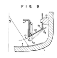
- Vertex Ao of member 22 is moved - (Ao - Ad) toward screen 4 because of its configuration.
- Frame 18 and mask 15, fixed to member 22, are moved toward screen 4 in a deformation direction defined by member 22, thereby correcting mislanding.
- mask 15 is thermally expanded by its temperature rise tm and its expansion, i.e., the displacement of the apertures thereof, corresponds to distance m from point PO to point Pd, as shown in Figs. 4 and 6.
- Correction distance D can be represented by the geometric expression: where tm is the distance from tube axis 20 to the outer wall surface of shadow mask 15, and tm is the temperature rise of shadow mask 15.
- correction distannce d of the displacement of vertex A is represented by the following geometric expression: where tf is a change in temperature rise of mask frame 17.
- angle ⁇ 45°
- angle a 45°
- angle a 45°
- the present inventors conducted a test using a 21 color cathode ray tube with the structure of the embodiment described above to obtain test results representing temperature changes in shadow mask 15 and mask frame 17, as shown in the graph of Fig. 7.
- shadow mask 15 was heated to a temperature of about 47°C during operation of the tube, while mask frame 17 was heated to a temperature of about 30°C.
- Correction angle a of resilient support member 22 (Fig. 4), for correcting mislanding of electron beams in association with the thermal expansion of shadow mask 15, was calculated according to equation (8) as follows: It is thus apparent that member 22 with an angle half of the deflection angle cannot correct mislanding of electron beams.
- the temperature of mask frame 17 is lower than that of shadow mask 15 for the following reason.
- a shortage of a scanning area is caused by variations in deflection angle in association with changes in high voltages in the television set In other words, lack of a reproduced image on the screen occurs.
- the deflection angle of the electron beams is set to be larger-than the rated angle.
- deflection power is increased, with resultant energy loss.
- electron beams 24A reflected by the side wall of mask 15 or frame 17 in Fig. 4 bombard the phosphor stripes of screen 4, thus greatly degrading the color purity.
- An increase in deflection angle to prevent lack of a reproduced image on the screen is normally limited to a range of t3%.
- the electron beams always bombard mask 15 and its peripheral portion to increase its temperature.
- electron beams directly bombarding frame 17 are few.
- the temperature rise in frame 17 is confined to conduction (including heat radiation) from high- temperature mask 15. Therefore, in a conventional color cathode ray tube, the temperature of frame 17 is always held to be lower than that of mask 15.
- member 22 when displacement F in association with the thermal expansion of frame 17 occurs, member 22 is deformed in any shape and ideal correction cannot be performed.
- vertex BO of member 22 when displacement F occurs, vertex BO of member 22 is deformed by ⁇ f in the same direction of the thermal expansion of frame 17 and a deformation force supposed to move vertex Ao of member 22 to position Ad is cancelled. At worst, mislanding is increased.
- Japanese Patent Publication No. 46-410 4 describes a color cathode ray tube (Fig. 3) wherein mask 5 is mounted to member 12 without using a mask frame, and the correction angle is set substantially half of the deflection angle to correct landing of the electron beams.
- this color cathode ray tube since a mask frame is not used, the thermal expansion of shadow mask 5 is directly applied to resilient support member 12.
- required correction distance D represented by equation (2) is substantially the same as actual correction distance d of member 12, which is represented by equation (3).
- the present inventors made a test using 21", 90° deflection and 28", 110 0 deflection color cathode ray tubes. Test results will be described in detail with reference to Fig. 9. Time is plotted along the abscissa, and the mislanding amounts of the electron beams are plotted along the ordinate. Mislanding of the electron beams was measured at a point on a diagonal axis 330 mm removed from the center of the screen when the cathode ray tubes were operated with a white screen at a voltage of 25 kV and a beam current density of 1.2 ⁇ A/cm 2 . A horizontal direction removed from the center of the phosphor screen was defined as a positive direction, and the opposite direction was defined as a negative direction.
- characteristic curve 1 represents changes in the conventional 21", 90° deflection color cathode ray tube wherein a mask frame is locked to substantially the central side walls of respective sides of the rectangular panel through a bimetal member.
- Characteristic curve II shows data obtained using a 21", 90° deflection cathode ray tube according to the present invention.
- curve 11 shows data of a cathode ray tube wherein mask 15 supported by frame 17 is locked by members 22 on the four comers of the inner surface of rectangular panel 1.
- angle a between axis 20 and inclined bridge section 22A of member 22 was set to be 57° in consideration of the temperature difference (represented by equation (10)) between mask frame 17 and shadow mask 15 during operation, and flexure ⁇ f (Fig. 8) of member 22.
- characteristic curve III of Fig. 9 shows a case wherein the same 21", 90° deflection color cathode ray tube as in curve 11 was used, angle a between tube axis and the inclinded bridge section 22A of member 22 was set to be 45°, or half of the deflection angle in the same manner as in Japanese Patent Publication No. 58-144, without considering a temperature difference between mask frame 17 and mask 15 during operation. Since the landing- error correction effect of frame support member 22 was small, a mislanding error of about 40 ⁇ m occurred 90 minutes after starting operation.
- Characteristic curve lV shows changes in mislanding as a function time in a 28", 110° deflection cathode ray tube in which angle a of the mask support is half of the deflection angle, i.e., 55° (half of the deflection angle of 110°), in the same manner as in Japanese Patent Publication Nos. 58-144 and 46-4104.
- a mislanding error was increased to 50 ⁇ m or more, 90 minutes after starting operation.
- angle a of the resilient support member is set to be half of the deflection angle without considering the temperature difference between the mask frame and the shadow mask, high color purity cannot be maintained for a long period of time.
- Characteristic curve V shows a mislanding error as a function time in a 28", 110° deflection cathode ray tube wherein mask frame 17 of the same cold-rolled steel plate mainly made of Fe as in the color cathode ray tubes for curves I to IV of Fig. 9 and shadow mask 15 of an invar were used, and angle a of the resilient support member was half, i.e., 55°, of the deflection angle in the same manner as in the prior art Japanese Patent Publication Nos. 58-144 and 46-4104.
- the mislanding error represented by curve V was shown to be as large as 80 ⁇ m or more 90 minutes after starting operation.
- the principle of the present invention was applied to a color cathode ray tube wherein a shadow mask made of an invar and a mask frame made of a cold-rolled steel plate mainly made of Fe were used, and angles a were the ideal 45° in the 21", 90° deflection cathode ray tube and 4 0° in the 28", 110° deflection cathode ray tube, thus obtaining curve If shown in Fig. 9.
- mislanding of the electron beams in association with the thermal expansion of a shadow mask fixed to a mask frame through a support member with an inclined bridge section so as to provide angle a between the tube axis and the support member, can be set in consideration of the temperature difference between the mask frame and the shadow mask such that
- An electron beam 24 scanning area is minimized in a normal color cathode ray tube to decrease the deflection power. Electron beams therefore do not substantially bombard the mask frame supporting the peripheral portion of the shadow mask. Ratio tm/tf of the temperature rise tm of the shadow mask to temperature rise tf of the mask frame is substantially 1.57, even if the temperatures of the mask frame and the shadow mask vary in accordance with the type of color cathode ray tube.
- the rigidity of the mask frame as a support frame is increased, and the mask frame can therefore be made thin, when compared with a conventional mask frame.
- the thickness of the mask frame is set to be 0.5 mm
- the weight of a 21" color cathode ray tube can be decreased to about 70% that of a tube containing a 1.6-mm thick mask frame.
- the weight of the conventional 1.6-mm thick mask frame is about 1.6 kg
- the weight of the 0.5-mm thick mask frame is decreased to about 0.5 kg. This light weight also reduces mislanding of the electron beams when impact accidentally acts on the color cathode ray tube.
- the present invention is exemplified by the color cathode tube wherein the shadow mask is suspended at four comers of the rectangular panel.
- the present invention is not limited to this.
- the present invention can also be applied to a structure wherein the shadow mask is suspended at substantially a center portion of the long and short sides of the rectangular panel, and to a structure wherein the shadow mask is suspended through resilient support members each of which have a bridge section inclined at angle a to the tube axis and is engaged with stud pin, to achieve the same effect as in the above embodiment
- the simple structure provided by the present invention can greatly decrease mislanding for a long period of time after an initial operation period, effectively preventing color purity degradation such as color misregistration or irregular color distribution, thereby providing color cathode ray tubes suitable for mass production.
Applications Claiming Priority (4)
| Application Number | Priority Date | Filing Date | Title |
|---|---|---|---|
| JP4665285 | 1985-03-11 | ||
| JP46652/85 | 1985-03-11 | ||
| JP266014/85 | 1985-11-28 | ||
| JP60266014A JPS62126527A (ja) | 1985-11-28 | 1985-11-28 | カラ−受像管 |
Publications (3)
| Publication Number | Publication Date |
|---|---|
| EP0195357A2 true EP0195357A2 (de) | 1986-09-24 |
| EP0195357A3 EP0195357A3 (en) | 1988-10-12 |
| EP0195357B1 EP0195357B1 (de) | 1995-09-13 |
Family
ID=26386755
Family Applications (1)
| Application Number | Title | Priority Date | Filing Date |
|---|---|---|---|
| EP86103265A Expired - Lifetime EP0195357B1 (de) | 1985-03-11 | 1986-03-11 | Farbbildröhre |
Country Status (6)
| Country | Link |
|---|---|
| US (1) | US4652792A (de) |
| EP (1) | EP0195357B1 (de) |
| KR (1) | KR890004842B1 (de) |
| CN (1) | CN1015844B (de) |
| DE (1) | DE3650388T2 (de) |
| IN (1) | IN164873B (de) |
Cited By (3)
| Publication number | Priority date | Publication date | Assignee | Title |
|---|---|---|---|---|
| EP0268485A2 (de) * | 1986-11-20 | 1988-05-25 | Kabushiki Kaisha Toshiba | Farbbildröhre |
| EP0488527A1 (de) * | 1990-10-27 | 1992-06-03 | Samsung Display Devices Co., Ltd. | Schattenmaskenstruktur einer Farbkathodenstrahlröhre |
| EP0281114B1 (de) * | 1987-03-06 | 1993-11-10 | Kabushiki Kaisha Toshiba | Farbbildröhre |
Families Citing this family (14)
| Publication number | Priority date | Publication date | Assignee | Title |
|---|---|---|---|---|
| KR900004258B1 (ko) | 1987-01-27 | 1990-06-18 | 가부시끼가이샤 도시바 | 칼라수상관 |
| JP2965254B2 (ja) * | 1988-01-22 | 1999-10-18 | 株式会社東芝 | カラー受像管の製造方法 |
| KR940003390Y1 (ko) * | 1991-12-06 | 1994-05-23 | 삼성전관 주식회사 | 마스크프레임 지지체 |
| EP0595405B1 (de) * | 1992-10-28 | 1996-09-04 | Koninklijke Philips Electronics N.V. | Farbkathodenstrahlröhre |
| JP3516462B2 (ja) * | 1993-05-20 | 2004-04-05 | ソニー株式会社 | 陰極線管の製造方法 |
| JP3259552B2 (ja) * | 1994-12-12 | 2002-02-25 | 三菱電機株式会社 | カラーブラウン管用色選別電極構体 |
| US6232710B1 (en) | 1995-09-18 | 2001-05-15 | Hitachi, Ltd. | Color cathode ray tube with mask springs |
| DE69530618T2 (de) * | 1995-09-18 | 2004-03-11 | Hitachi, Ltd. | Farb-kathodenstrahlröhre |
| JPH10312756A (ja) * | 1997-05-12 | 1998-11-24 | Toshiba Corp | 陰極線管 |
| KR100229729B1 (ko) * | 1997-09-03 | 1999-11-15 | 구자홍 | 칼라음극선관용 코너스프링 |
| KR100237219B1 (ko) * | 1997-10-08 | 2000-01-15 | 손욱 | 컬러 음극선관의 마스크 어셈블리 |
| US5982085A (en) * | 1997-12-23 | 1999-11-09 | Philips Electronics North America Corporation | Color cathode ray tube with improved shadow mask mounting system |
| JP2000011911A (ja) * | 1998-06-26 | 2000-01-14 | Hitachi Ltd | シャドウマスクを備えたカラー陰極線管 |
| KR20010096031A (ko) * | 2000-04-17 | 2001-11-07 | 김순택 | 칼라 브라운관의 마스크 프레임 지지체 |
Citations (4)
| Publication number | Priority date | Publication date | Assignee | Title |
|---|---|---|---|---|
| US3529199A (en) * | 1967-06-30 | 1970-09-15 | Philips Corp | Shadow mask having elements bridging corners of integral,longitudinally-extending portions |
| US3803436A (en) * | 1965-07-16 | 1974-04-09 | A Morrell | Shadow mask mounting assemblies |
| JPS53144252A (en) * | 1977-05-20 | 1978-12-15 | Matsushita Electronics Corp | Color picture tube |
| EP0216371A2 (de) * | 1985-09-25 | 1987-04-01 | Kabushiki Kaisha Toshiba | Farbbildröhre |
Family Cites Families (3)
| Publication number | Priority date | Publication date | Assignee | Title |
|---|---|---|---|---|
| JPS4853668A (de) * | 1971-11-08 | 1973-07-27 | ||
| JPS58144A (ja) * | 1981-06-25 | 1983-01-05 | Fujitsu Ltd | 半導体装置 |
| US4482426A (en) * | 1984-04-02 | 1984-11-13 | Rca Corporation | Method for etching apertures into a strip of nickel-iron alloy |
-
1986
- 1986-02-27 KR KR1019860001365A patent/KR890004842B1/ko not_active IP Right Cessation
- 1986-03-10 IN IN88/BOM/86A patent/IN164873B/en unknown
- 1986-03-10 CN CN86102402A patent/CN1015844B/zh not_active Expired
- 1986-03-11 DE DE3650388T patent/DE3650388T2/de not_active Expired - Lifetime
- 1986-03-11 EP EP86103265A patent/EP0195357B1/de not_active Expired - Lifetime
- 1986-03-11 US US06/838,811 patent/US4652792A/en not_active Expired - Lifetime
Patent Citations (5)
| Publication number | Priority date | Publication date | Assignee | Title |
|---|---|---|---|---|
| US3803436A (en) * | 1965-07-16 | 1974-04-09 | A Morrell | Shadow mask mounting assemblies |
| US3529199A (en) * | 1967-06-30 | 1970-09-15 | Philips Corp | Shadow mask having elements bridging corners of integral,longitudinally-extending portions |
| JPS53144252A (en) * | 1977-05-20 | 1978-12-15 | Matsushita Electronics Corp | Color picture tube |
| JPS58144B2 (ja) * | 1977-05-20 | 1983-01-05 | 松下電子工業株式会社 | カラ−受像管 |
| EP0216371A2 (de) * | 1985-09-25 | 1987-04-01 | Kabushiki Kaisha Toshiba | Farbbildröhre |
Non-Patent Citations (8)
| Title |
|---|
| CRC Handbook of Chemistry and Physics, 59th edition, 1978-79, CRC Press, Inc., West-Palm Beach, Florida, US, pages D-223 - D-225 * |
| English translation of JP-A-54-159 166 * |
| McGraw-Hill Encyclopedia of Science and Technology, 1977, p. 570 * |
| Modern Technical Physics, Fourth Edition, A. Beiser, The Benjamin/Cummings Publishing Company, Inc., 1983, p. 342 * |
| PATENT ABSTRACTS OF JAPAN, Unexamined Applications, E FIELD, Vol. 3, No. 150, December 11, 1979 The Patent Office Japanese Government page 12 E 158 JP-A-54 129 877 (Hitachi) * |
| PATENT ABSTRACTS OF JAPAN, Unexamined Applications, E FIELD, Vol. 4, No. 18, February 13, 1980 The Patent Office Japanese Government page 166 E 171 JP-A-54 159 166 (Hitachi) * |
| Patent Abstracts of Japan, Vol. 3, No. 17, (E-90), 14.02.1979 & JP-A-53-144 252 & JP-B2-58 000 144 * |
| Physik, Dreizehnte Auflage, C. Gerthsen, Springer-Verlag, Berlin, DE, 1977, p. 157 * |
Cited By (4)
| Publication number | Priority date | Publication date | Assignee | Title |
|---|---|---|---|---|
| EP0268485A2 (de) * | 1986-11-20 | 1988-05-25 | Kabushiki Kaisha Toshiba | Farbbildröhre |
| EP0268485A3 (en) * | 1986-11-20 | 1988-10-12 | Kabushiki Kaisha Toshiba | Colour picture tube |
| EP0281114B1 (de) * | 1987-03-06 | 1993-11-10 | Kabushiki Kaisha Toshiba | Farbbildröhre |
| EP0488527A1 (de) * | 1990-10-27 | 1992-06-03 | Samsung Display Devices Co., Ltd. | Schattenmaskenstruktur einer Farbkathodenstrahlröhre |
Also Published As
| Publication number | Publication date |
|---|---|
| KR860007704A (ko) | 1986-10-15 |
| US4652792A (en) | 1987-03-24 |
| CN86102402A (zh) | 1986-10-15 |
| DE3650388D1 (de) | 1995-10-19 |
| EP0195357A3 (en) | 1988-10-12 |
| DE3650388T2 (de) | 1996-02-29 |
| KR890004842B1 (ko) | 1989-11-29 |
| CN1015844B (zh) | 1992-03-11 |
| IN164873B (de) | 1989-06-24 |
| EP0195357B1 (de) | 1995-09-13 |
Similar Documents
| Publication | Publication Date | Title |
|---|---|---|
| US4652792A (en) | Color cathode ray tube with resilient shadow mask support | |
| US4827180A (en) | Color picture tube with support members for the mask frame | |
| EP0304922B1 (de) | Farbbildröhre | |
| US4677339A (en) | Color cathode ray tube | |
| EP0278709B1 (de) | Kathodenstrahlröhre mit einer Lochmaske für schwache Überablenkung | |
| EP0708973B1 (de) | Lochmaske mit spannrahmenanordnung für eine kathodenstrahlröhre | |
| US4613785A (en) | Color picture tube having an improved simplified support structure for a color selection electrode | |
| US4697119A (en) | Color cathode ray tube having a non-spherical curved mask | |
| JPS59141150A (ja) | シヤドウマスク式カラ−受像管 | |
| EP0325207B1 (de) | Farbbildröhre | |
| US6020680A (en) | Color cathode ray tube | |
| US6013975A (en) | Color display tube having a shadow mask | |
| EP0216371A2 (de) | Farbbildröhre | |
| US5252889A (en) | Color CRT with means for correcting mislanding of electron beams | |
| JP2525820B2 (ja) | カラ−受像管 | |
| JP2565899B2 (ja) | カラ−受像管 | |
| US6294864B1 (en) | Color cathode-ray tube with shadow mask having L-shaped bi-metallic springs | |
| US6232710B1 (en) | Color cathode ray tube with mask springs | |
| JP2614208B2 (ja) | カラー受像管 | |
| EP0677863B1 (de) | Farb Kathodenstrahlröhre | |
| US20010015608A1 (en) | Color cathode ray tube | |
| JPS62126527A (ja) | カラ−受像管 | |
| JPS63158731A (ja) | カラ−受像管 | |
| JPH0685301B2 (ja) | カラ−受像管 | |
| JPH059895B2 (de) |
Legal Events
| Date | Code | Title | Description |
|---|---|---|---|
| PUAI | Public reference made under article 153(3) epc to a published international application that has entered the european phase |
Free format text: ORIGINAL CODE: 0009012 |
|
| 17P | Request for examination filed |
Effective date: 19860408 |
|
| AK | Designated contracting states |
Kind code of ref document: A2 Designated state(s): DE FR GB |
|
| PUAL | Search report despatched |
Free format text: ORIGINAL CODE: 0009013 |
|
| AK | Designated contracting states |
Kind code of ref document: A3 Designated state(s): DE FR GB |
|
| 17Q | First examination report despatched |
Effective date: 19900323 |
|
| GRAA | (expected) grant |
Free format text: ORIGINAL CODE: 0009210 |
|
| AK | Designated contracting states |
Kind code of ref document: B1 Designated state(s): DE FR GB |
|
| REF | Corresponds to: |
Ref document number: 3650388 Country of ref document: DE Date of ref document: 19951019 |
|
| ET | Fr: translation filed | ||
| PLBE | No opposition filed within time limit |
Free format text: ORIGINAL CODE: 0009261 |
|
| STAA | Information on the status of an ep patent application or granted ep patent |
Free format text: STATUS: NO OPPOSITION FILED WITHIN TIME LIMIT |
|
| 26N | No opposition filed | ||
| REG | Reference to a national code |
Ref country code: GB Ref legal event code: 746 Effective date: 19981008 |
|
| REG | Reference to a national code |
Ref country code: FR Ref legal event code: D6 |
|
| REG | Reference to a national code |
Ref country code: GB Ref legal event code: IF02 |
|
| PGFP | Annual fee paid to national office [announced via postgrant information from national office to epo] |
Ref country code: DE Payment date: 20050304 Year of fee payment: 20 |
|
| PGFP | Annual fee paid to national office [announced via postgrant information from national office to epo] |
Ref country code: FR Payment date: 20050308 Year of fee payment: 20 |
|
| PGFP | Annual fee paid to national office [announced via postgrant information from national office to epo] |
Ref country code: GB Payment date: 20050309 Year of fee payment: 20 |
|
| PG25 | Lapsed in a contracting state [announced via postgrant information from national office to epo] |
Ref country code: GB Free format text: LAPSE BECAUSE OF EXPIRATION OF PROTECTION Effective date: 20060310 |
|
| REG | Reference to a national code |
Ref country code: GB Ref legal event code: PE20 |