EP0194698B1 - Duschkabinen-Abtrennung - Google Patents
Duschkabinen-Abtrennung Download PDFInfo
- Publication number
- EP0194698B1 EP0194698B1 EP86103451A EP86103451A EP0194698B1 EP 0194698 B1 EP0194698 B1 EP 0194698B1 EP 86103451 A EP86103451 A EP 86103451A EP 86103451 A EP86103451 A EP 86103451A EP 0194698 B1 EP0194698 B1 EP 0194698B1
- Authority
- EP
- European Patent Office
- Prior art keywords
- door
- guide rail
- shower cabin
- partition arrangement
- vertical
- Prior art date
- Legal status (The legal status is an assumption and is not a legal conclusion. Google has not performed a legal analysis and makes no representation as to the accuracy of the status listed.)
- Expired
Links
- 238000005192 partition Methods 0.000 claims abstract description 18
- 230000005540 biological transmission Effects 0.000 claims abstract description 5
- 238000010276 construction Methods 0.000 description 2
- 230000001419 dependent effect Effects 0.000 description 1
Images


Classifications
-
- E—FIXED CONSTRUCTIONS
- E05—LOCKS; KEYS; WINDOW OR DOOR FITTINGS; SAFES
- E05D—HINGES OR SUSPENSION DEVICES FOR DOORS, WINDOWS OR WINGS
- E05D15/00—Suspension arrangements for wings
- E05D15/26—Suspension arrangements for wings for folding wings
-
- A—HUMAN NECESSITIES
- A47—FURNITURE; DOMESTIC ARTICLES OR APPLIANCES; COFFEE MILLS; SPICE MILLS; SUCTION CLEANERS IN GENERAL
- A47K—SANITARY EQUIPMENT NOT OTHERWISE PROVIDED FOR; TOILET ACCESSORIES
- A47K3/00—Baths; Douches; Appurtenances therefor
- A47K3/28—Showers or bathing douches
- A47K3/30—Screens or collapsible cabinets for showers or baths
- A47K3/36—Articulated screens
- A47K3/362—Articulated screens comprising sliding and articulated panels
-
- E—FIXED CONSTRUCTIONS
- E06—DOORS, WINDOWS, SHUTTERS, OR ROLLER BLINDS IN GENERAL; LADDERS
- E06B—FIXED OR MOVABLE CLOSURES FOR OPENINGS IN BUILDINGS, VEHICLES, FENCES OR LIKE ENCLOSURES IN GENERAL, e.g. DOORS, WINDOWS, BLINDS, GATES
- E06B3/00—Window sashes, door leaves, or like elements for closing wall or like openings; Layout of fixed or moving closures, e.g. windows in wall or like openings; Features of rigidly-mounted outer frames relating to the mounting of wing frames
- E06B3/32—Arrangements of wings characterised by the manner of movement; Arrangements of movable wings in openings; Features of wings or frames relating solely to the manner of movement of the wing
- E06B3/48—Wings connected at their edges, e.g. foldable wings
- E06B3/481—Wings foldable in a zig-zag manner or bi-fold wings
-
- E—FIXED CONSTRUCTIONS
- E05—LOCKS; KEYS; WINDOW OR DOOR FITTINGS; SAFES
- E05Y—INDEXING SCHEME ASSOCIATED WITH SUBCLASSES E05D AND E05F, RELATING TO CONSTRUCTION ELEMENTS, ELECTRIC CONTROL, POWER SUPPLY, POWER SIGNAL OR TRANSMISSION, USER INTERFACES, MOUNTING OR COUPLING, DETAILS, ACCESSORIES, AUXILIARY OPERATIONS NOT OTHERWISE PROVIDED FOR, APPLICATION THEREOF
- E05Y2900/00—Application of doors, windows, wings or fittings thereof
- E05Y2900/10—Application of doors, windows, wings or fittings thereof for buildings or parts thereof
- E05Y2900/114—Application of doors, windows, wings or fittings thereof for buildings or parts thereof for showers
Definitions
- the present invention relates to a shower cubicle partition with a folding door with a plurality of door leaves, wherein an outer door leaf is articulated to a vertical frame spar and the other outer door leaf is forcibly coupled to an adjacent door leaf in the area of adjacent vertical spars by a gear, that a pivoting movement of the outer door leaf is transmitted at the same angle to the neighboring door leaf and that the two coupled door leaves are connected in the transmission area to a guide part guided along an upper, horizontal guide rail.
- the guide part is guided in correspondingly profiled guide rails and the connection of the door leaves on the guide part is usually offset relative to the longitudinal axis of the guide rail to the outside of the shower cubicle partition.
- the guide part can be jammed in the guide rail, so that considerable structural precautions must be taken to ensure that the guide part can be moved easily.
- the object of the present invention is to improve a shower cubicle partition of the generic type in such a way that, with the simplest construction of the guide rail and guide part, safe and easy sliding of the guide part relative to the guide rail is possible.
- the guide part encloses the guide rail and in that the two door leaves are connected to the guide side below and in a common vertical plane with the longitudinal axis of the guide rail.
- the advantage of the invention is that the door leaves are connected to the guide rail in the center of its longitudinal axis, so that only vertical forces can be transmitted to the guide rail from the guide part.
- This arrangement practically prevents the guide part from jamming or jamming on the guide rail, it being a matter of course that the guide rail is of such a stable design that the guide rail does not bend due to the vertical loads.
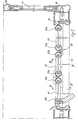
- the shower cubicle partition shown in perspective in FIG. 1 is equipped with a folding door, which is provided with the reference number 10 as a whole.
- the folding door 10 in the illustrated embodiment consists of three door leaves 11, 12 and 13.
- the outer door leaf 13 is articulated to a vertical frame member 14 in a manner known per se.
- the other outer door leaf 11 is forcibly coupled to the adjacent middle door leaf 12 in a manner known per se and for this reason not shown in detail by means of a gear such that a pivoting movement of the outer door leaf 11 is transmitted at the same angle to the adjacent central door leaf 12.
- the gear mechanism mentioned is advantageously arranged in a guide part 15 which is guided so as to be longitudinally displaceable on an upper, horizontal guide rail 16.
- the guide part 15 encloses the guide rail 16 and the connection of the door leaves 11 and 12 to the guide part 15 is selected such that the adjacent vertical bars 11a and 12a of the door leaves 11 and 12 in question below and lie in a common vertical plane with the longitudinal axis of the guide rail 16.
- the guide part 15 can thus only transmit exactly vertical forces to the guide rail 16.
- the vertical bars 11a and 12a project beyond their respective upper, horizontally running bars 11b, 12b and 13b.
- the vertical bars 11 a, 12a and 13a end below the guide rail 16.
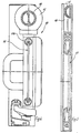
- This construction simplifies the connection of the vertical bars 11 and 12a to the guide part 15 as well as a hinge connection between the adjacent vertical bars 12a and 13a in the area between the two door leaves 12 and 13.
- the guide rail 16 is designed in the illustrated embodiment as a round profile. It is also conceivable to use symmetrical, non-circular profiles.
- FIG. 3 shows that the guide rail 16 can be covered by a panel 20 facing the outside of the shower cubicle partition, so that the guide side 15 is then no longer visible.
- the diaphragm 20 has not been shown in FIG. 1.
- the upper spar 19 has a semicircular cross section, the radius of the profile corresponding to the radius of the guide rail 16. 5, it is also possible to produce the upper spar 19 from a closed circular profile, the diameter of which is equal to the diameter of the guide rail 16. If the guide rail 16 consists of a symmetrical non-circular profile, it makes sense to produce the upper spar 19 from the same profile or from a correspondingly halved profile.
Landscapes
- Health & Medical Sciences (AREA)
- Public Health (AREA)
- Engineering & Computer Science (AREA)
- Epidemiology (AREA)
- General Health & Medical Sciences (AREA)
- Civil Engineering (AREA)
- Structural Engineering (AREA)
- Mechanical Engineering (AREA)
- Wing Frames And Configurations (AREA)
- Extensible Doors And Revolving Doors (AREA)
Description
- Die vorliegende Erfindung bezieht sich auf eine Duschkabinen-Abtrennung mit einer Falttür mit mehreren Türflügeln, wobei ein äusserer Türflügel gelenkig an einem vertikalen Rahmenholm angelenkt und der andere äussere Türflügel mit einem benachbarten Türflügel im Bereich benachbarter, vertikaler Holme durch ein Getriebe zwangsgekoppelt ist, derart, dass eine Schwenkbewegung des äusseren Türflügels winkelgleich auf den benachbarten Türflügel übertragen wird und dass die beiden gekoppelten Türflügel im Getriebebereich an einem längs einer oberen, horizontalen Führungsschiene geführten Führungsteil angeschlossen sind.
- Duschkabinen-Abtrennungen der vorerwähnten Art sind an sich bekannt.
- Bei den vorbekannten Duschkabinen-Abtrennungen der gattungsgemässen Art ist das Führungsteil in entsprechend profilierten Führungsschienen geführt und der Anschluss der Türflügel am Führungsteil ist gegenüber der Längsachse der Führungsschiene meist zur Aussenseite der Duschkabinen-Abtrennung hin versetzt. Es besteht dadurch die Gefahr, dass das Führungsteil in der Führungsschiene verklemmt werden kann, so dass beträchtliche konstruktive Vorkehrungen getroffen werden müssen, um eine leichtgängige Verschiebbarkeit des Führungsteiles zu gewährleisten.
- Der vorliegenden Erfindung liegt die Aufgabe zugrunde, eine Duschkabinen-Abtrennung der gattungsgemässen Art dahingehend zu verbessern, dass bei einfachster Konstruktion von Führungsschiene und Führungsteil ein sicheres und leichtes Gleiten des Führungsteiles gegenüber der Führungsschiene möglich ist.
- Diese Aufgabe wird erfindungsgemäss dadurch gelöst, dass das Führungsteil die Führungsschiene umschliesst und dass die beiden Türflügel unterhalb und in einer gemeinsamen vertikalen Ebene mit der Längsachse der Führungsschiene am Führungsteit angeschlossen sind.
- Mit der Erfindung wird der Vorteil erzielt, dass derAnschlussderTürflügel an der Führungsschiene mittig zu deren Längsachse erfolgt, so dass vom Führungsteil ausgehend ausschliesslich vertikale Kräfte auf die Führungsschiene übertragen werden können. Durch diese Anordnungwird ein Verkanten oder Verklemmen des Führungsteiles auf der Führungsschiene praktisch verhindert, wobei selbstverständliche Voraussetzung ist, dass die Führungsschiene derart stabil ausgebildet ist, dass durch die vertikalen Belastungen keine Durchbiegung der Führungsschiene eintritt.
- Weitere Merkmale der Erfindung sind Gegenstand von abhängigen Ansprüchen.
- In den beigefügten Zeichnungen istein Ausführungsbeispiel der Erfindung dargestellt, welches im folgenden näher beschrieben wird.
- Es zeigen:
- Fig. 1 eine perspektivische Darstellung einer Duschkabinen-Abtrennung mit teilweise geöffneter Falttür,
- Fig. 2 einen Horizontalschnitt durch die Duschkabinen-Abtrennung gemäss Fig. 1 bei geschlossener Falttür,
- Fig. 3 einen Schnitt nach der Linie III-III in Fig. 2,
- Fig. 4 einen Schnitt nach der Linie IV-IV in Fig. 2,
- Fig. 5 einen Schnitt nach der Linie V-V in Fig. 1.
- Die in Fig. 1 in perspektivischer Darstellung gezeigte Duschkabinen-Abtrennung ist mit einer Falttür ausgestattet, die insgesamt mit dem Bezugszeichen 10 versehen ist. Die Falttür 10 besteht im dargestellten Ausführungsbeispiel aus drei Türflügeln 11, 12 und 13.
- Der äussere Türflügel 13 ist in an sich bekannter Weise an einem vertikalen Rahmenholm 14 gelenkig angeschlossen. Der andere äussere Türflügel 11 ist mit dem benachbarten mittleren Türflügel 12 in an sich bekannter und aus diesem Grunde nicht näher dargestellter Weise über ein Getriebe zwangsgekoppelt, derart, dass eine Schwenkbewegung des äusseren Türflügels 11 winkel gleich auf den benachbarten mittleren Türflügel 12 übertragen wird.
- Das erwähnte Getriebe ist vorteilhafterweise in einem Führungsteil 15 angeordnet, welches auf einer oberen, horizontalen Führungsschiene 16 längsverschiebbar geführt ist.
- Wie die Fig. 1 und 4 deutlich zeigen, umschliesst das Führungsteil 15 die Führungsschiene 16 und der Anschluss der Türflügel 11 und 12 am Führungsteil 15 ist so gewählt, dass die einander benachbarten vertikalen Holme 11a und 12a der in Rede stehenden Türflügel 11 und 12 unterhalb und in einer gemeinsamen vertikalen Ebene mit der Längsachse der Führungsschiene 16 liegen.
- Es können durch das Führungsteil 15 somit nur exakt vertikale Kräfte auf die Führungsschiene 16 übertragen werden.
- Die vertikalen Holme 11a und 12a ragen ebenso wie die übrigen vertikalen Holme 13a des am vertikalen Holm 14 angelenkten äusseren Türflügels 13 über ihre jeweiligen oberen, horizontal verlaufenden Holme 11 b, 12b und 13b hinaus. Die vertikalen Holme 11 a, 12a und 13a enden andererseits unterhalb der Führungsschiene 16.
- Durch diese Konstruktion wird der Anschluss der vertikalen Holme 11 und 12a an das Führungsteil 15 ebenso vereinfacht wie eine Scharnierverbindung zwischen den benachbarten vertikalen Holmen 12a und 13a im Bereich zwischen den beiden Türflügeln 12 und 13.
- Die Führungsschiene 16 ist im dargestellten Ausführungsbeispiel als Rundprofil ausgebildet. Ebenso ist es denkbar, symmetrische, unrunde Profile einzusetzen.
- Fig. 3 zeigt, dass die Führungsschiene 16 durch eine zur Aussenseite der Duschkabinen-Abtrennung weisende Blende 20 verdeckt sein kann, so dass dann auch das Pührungsteit 15 nicht mehr sichtbar ist. Aus Gründen der Übersichtlichkeit ist auf die Darstellung dieser Blende 20 in Fig. 1 verzichtet worden.
- Fig. 5 macht deutlich, dass ein winklig zur Falttür 10 verlaufender starrer Flügel 17 der Duschkabinen-Abtrennung in einen aus vertikalen Holmen 18 sowie einem oberen, horizontalen Holm 19 bestehenden Rahmen eingesetzt ist. Dabei ist vorgesehen, den starren Flügel 17 unterhalb des oberen Holmes 19 enden zu lassen, so dass zwischen der Oberkante des starren Flügels 17 und dem oberen Holm 19 ein gleichgrosser Spalt entsteht wie zwischen den oberen Holmen 11 b bis 13b der Türflügel 11 bis 13 und der Führungsschiene 16.
- Fig. 5 macht besonders deutlich, dass der obere Holm 19 einen halbrunden Querschnitt aufweist, wobei der Radius des Profiles dem Radius der Führungsschiene 16 entspricht. Abweichend von der Darstellung gemäss Fig. 5 ist es auch möglich, den oberen Holm 19 aus einem geschlossenen kreisförmigen Profil herzustellen, wobei dessen Durchmesser gleich dem Durchmesser der Führungsschiene 16 ist. Besteht die Führungsschiene 16 aus einem symmetrischen unrunden Profil, ist es sinnvoll, den oberen Holm 19 aus dem gleichen Profil herzustellen oder aus einem entsprechend halbierten Profil.
Claims (8)
Priority Applications (1)
| Application Number | Priority Date | Filing Date | Title |
|---|---|---|---|
| AT86103451T ATE33540T1 (de) | 1985-03-15 | 1986-03-14 | Duschkabinen-abtrennung. |
Applications Claiming Priority (2)
| Application Number | Priority Date | Filing Date | Title |
|---|---|---|---|
| DE8507610U | 1985-03-15 | ||
| DE8507610U DE8507610U1 (de) | 1985-03-15 | 1985-03-15 | Duschkabinen-Abtrennung |
Publications (2)
| Publication Number | Publication Date |
|---|---|
| EP0194698A1 EP0194698A1 (de) | 1986-09-17 |
| EP0194698B1 true EP0194698B1 (de) | 1988-04-20 |
Family
ID=6778676
Family Applications (1)
| Application Number | Title | Priority Date | Filing Date |
|---|---|---|---|
| EP86103451A Expired EP0194698B1 (de) | 1985-03-15 | 1986-03-14 | Duschkabinen-Abtrennung |
Country Status (3)
| Country | Link |
|---|---|
| EP (1) | EP0194698B1 (de) |
| AT (1) | ATE33540T1 (de) |
| DE (1) | DE8507610U1 (de) |
Families Citing this family (4)
| Publication number | Priority date | Publication date | Assignee | Title |
|---|---|---|---|---|
| IT1190598B (it) * | 1986-06-16 | 1988-02-16 | Giancarlo Mazzoli | Sistema e mezzi per il montaggio rapido di cabine doccia di dimensioni diverse |
| DE3831521A1 (de) * | 1988-09-16 | 1990-03-22 | Semer Gmbh & Co Kg W | Klappwand, insbesondere schiebeklapptuer fuer duschabtrennungen u. dgl. |
| DE4106116A1 (de) * | 1991-02-27 | 1992-09-03 | Semer Gmbh & Co Kg W | Rahmen fuer trennwaende, insbesondere fuer duschabtrennungen u. dgl. |
| CN103590718A (zh) * | 2013-10-23 | 2014-02-19 | 平湖乐优卫浴有限公司 | 一种有折叠门的淋浴房 |
Family Cites Families (3)
| Publication number | Priority date | Publication date | Assignee | Title |
|---|---|---|---|---|
| US2092426A (en) * | 1935-11-29 | 1937-09-07 | Charles F Riddell | Bath fixture |
| US2095645A (en) * | 1937-05-17 | 1937-10-12 | Fred H Lewis | Bath fixture |
| FR2313531A1 (fr) * | 1975-06-05 | 1976-12-31 | Allard Sarl | Systeme de manoeuvre notamment pour bachage mecanique |
-
1985
- 1985-03-15 DE DE8507610U patent/DE8507610U1/de not_active Expired
-
1986
- 1986-03-14 EP EP86103451A patent/EP0194698B1/de not_active Expired
- 1986-03-14 AT AT86103451T patent/ATE33540T1/de not_active IP Right Cessation
Also Published As
| Publication number | Publication date |
|---|---|
| EP0194698A1 (de) | 1986-09-17 |
| ATE33540T1 (de) | 1988-05-15 |
| DE8507610U1 (de) | 1985-04-25 |
Similar Documents
| Publication | Publication Date | Title |
|---|---|---|
| EP1152112A2 (de) | Verstellbare Scharnier-Rahmen-Anordnung | |
| DE2648987A1 (de) | Bewegliche wand mit schiebe- und faltfluegel | |
| EP0628691B1 (de) | Dreh-Kipp-Beschlag für Fenster, Türen od.dgl. | |
| EP0194698B1 (de) | Duschkabinen-Abtrennung | |
| EP0128391B1 (de) | Bogenförmig verschiebbares Schiebetor | |
| EP3798390B1 (de) | Faltanlage | |
| EP0194697B1 (de) | Falttür für eine Duschkabine (I) | |
| DE4020559A1 (de) | Hohlkammerprofilverbindung | |
| WO1996023841A1 (de) | Leukoküpenfarbstoff-präparationen in granulatform | |
| EP0370437A1 (de) | Tür oder Fenster | |
| EP0074648B1 (de) | Rahmen für Bandfördervorrichtungen | |
| DE3427911C1 (de) | Duschabtrennung in Form einer Schiebetür | |
| EP0384218B1 (de) | Duschkabinen-Schiebetür | |
| EP2072744B1 (de) | Zargenprofil für eine Hebe-Schiebetür | |
| DE2520668A1 (de) | Treibstangenbeschlag fuer fenster, tueren oder dergleichen | |
| DE3417044C2 (de) | Dusch- und Badewannenabtrennung | |
| DE2547616C3 (de) | Feststehender Metallrahmen für horizontal bewegbare Schiebefenster oder Schiebetüren | |
| DE2645671A1 (de) | Deckengliedertor | |
| CH640301A5 (de) | Duschkabinenschiebetuer. | |
| EP2584129B1 (de) | Schiebefenster oder schiebetür | |
| DE2436822C2 (de) | Schiebefenster | |
| EP1288131B1 (de) | Faltwandcontainer | |
| DE2708453A1 (de) | Kastenaufbau von fahrzeugen mit mindestens einer verschiebbaren tuer | |
| EP0751732A1 (de) | Tür für duschkabinen/duschabtrennungen | |
| DE1924292C (de) | Dreh-Kipp-Beschlag für Fenster oder Türen mit einer in jedem lotrechten Seitenholm des Flügelrahmens verdeckt angeordneten, auf- und abbewegbaren Treibstange |
Legal Events
| Date | Code | Title | Description |
|---|---|---|---|
| PUAI | Public reference made under article 153(3) epc to a published international application that has entered the european phase |
Free format text: ORIGINAL CODE: 0009012 |
|
| AK | Designated contracting states |
Kind code of ref document: A1 Designated state(s): AT CH FR GB LI |
|
| 17P | Request for examination filed |
Effective date: 19861018 |
|
| 17Q | First examination report despatched |
Effective date: 19870728 |
|
| GRAA | (expected) grant |
Free format text: ORIGINAL CODE: 0009210 |
|
| AK | Designated contracting states |
Kind code of ref document: B1 Designated state(s): AT CH FR GB LI |
|
| REF | Corresponds to: |
Ref document number: 33540 Country of ref document: AT Date of ref document: 19880515 Kind code of ref document: T |
|
| GBT | Gb: translation of ep patent filed (gb section 77(6)(a)/1977) | ||
| ET | Fr: translation filed | ||
| PLBI | Opposition filed |
Free format text: ORIGINAL CODE: 0009260 |
|
| 26 | Opposition filed |
Opponent name: DUSCHOLUX GMBH Effective date: 19890131 |
|
| PLBN | Opposition rejected |
Free format text: ORIGINAL CODE: 0009273 |
|
| STAA | Information on the status of an ep patent application or granted ep patent |
Free format text: STATUS: OPPOSITION REJECTED |
|
| 27O | Opposition rejected |
Effective date: 19901103 |
|
| REG | Reference to a national code |
Ref country code: CH Ref legal event code: PUE Owner name: KORALLE SANITAERPRODUKTE GMBH & CO. Ref country code: GB Ref legal event code: 732E |
|
| REG | Reference to a national code |
Ref country code: FR Ref legal event code: TP |
|
| REG | Reference to a national code |
Ref country code: GB Ref legal event code: IF02 |
|
| PGFP | Annual fee paid to national office [announced via postgrant information from national office to epo] |
Ref country code: FR Payment date: 20020318 Year of fee payment: 17 |
|
| PGFP | Annual fee paid to national office [announced via postgrant information from national office to epo] |
Ref country code: AT Payment date: 20020322 Year of fee payment: 17 |
|
| PGFP | Annual fee paid to national office [announced via postgrant information from national office to epo] |
Ref country code: GB Payment date: 20030218 Year of fee payment: 18 |
|
| PG25 | Lapsed in a contracting state [announced via postgrant information from national office to epo] |
Ref country code: AT Free format text: LAPSE BECAUSE OF NON-PAYMENT OF DUE FEES Effective date: 20030314 |
|
| PGFP | Annual fee paid to national office [announced via postgrant information from national office to epo] |
Ref country code: CH Payment date: 20030324 Year of fee payment: 18 |
|
| PG25 | Lapsed in a contracting state [announced via postgrant information from national office to epo] |
Ref country code: FR Free format text: LAPSE BECAUSE OF NON-PAYMENT OF DUE FEES Effective date: 20031127 |
|
| REG | Reference to a national code |
Ref country code: FR Ref legal event code: ST |
|
| PG25 | Lapsed in a contracting state [announced via postgrant information from national office to epo] |
Ref country code: GB Free format text: LAPSE BECAUSE OF NON-PAYMENT OF DUE FEES Effective date: 20040314 |
|
| PG25 | Lapsed in a contracting state [announced via postgrant information from national office to epo] |
Ref country code: LI Free format text: LAPSE BECAUSE OF NON-PAYMENT OF DUE FEES Effective date: 20040331 Ref country code: CH Free format text: LAPSE BECAUSE OF NON-PAYMENT OF DUE FEES Effective date: 20040331 |
|
| GBPC | Gb: european patent ceased through non-payment of renewal fee |
Effective date: 20040314 |
|
| REG | Reference to a national code |
Ref country code: CH Ref legal event code: PL |