EP0193531B1 - Verfahren und vorrichtung zum ausrichten eines in zum beispiel eine maueraussparung einzubringenden elementes wie rahmen - Google Patents
Verfahren und vorrichtung zum ausrichten eines in zum beispiel eine maueraussparung einzubringenden elementes wie rahmen Download PDFInfo
- Publication number
- EP0193531B1 EP0193531B1 EP85900103A EP85900103A EP0193531B1 EP 0193531 B1 EP0193531 B1 EP 0193531B1 EP 85900103 A EP85900103 A EP 85900103A EP 85900103 A EP85900103 A EP 85900103A EP 0193531 B1 EP0193531 B1 EP 0193531B1
- Authority
- EP
- European Patent Office
- Prior art keywords
- frame
- air bags
- wall opening
- longitudinal
- jambs
- Prior art date
- Legal status (The legal status is an assumption and is not a legal conclusion. Google has not performed a legal analysis and makes no representation as to the accuracy of the status listed.)
- Expired
Links
- 238000000034 method Methods 0.000 title claims abstract description 20
- 239000006260 foam Substances 0.000 claims description 6
- 230000008878 coupling Effects 0.000 claims 2
- 238000010168 coupling process Methods 0.000 claims 2
- 238000005859 coupling reaction Methods 0.000 claims 2
- 238000005086 pumping Methods 0.000 claims 2
- 238000009434 installation Methods 0.000 abstract description 3
- 125000006850 spacer group Chemical group 0.000 abstract 1
- 238000005187 foaming Methods 0.000 description 2
- 238000004519 manufacturing process Methods 0.000 description 2
- 238000003892 spreading Methods 0.000 description 2
- 238000004026 adhesive bonding Methods 0.000 description 1
- 238000005253 cladding Methods 0.000 description 1
- 210000000078 claw Anatomy 0.000 description 1
- 238000010276 construction Methods 0.000 description 1
- 230000001419 dependent effect Effects 0.000 description 1
- 238000010586 diagram Methods 0.000 description 1
- 230000000694 effects Effects 0.000 description 1
- 238000005516 engineering process Methods 0.000 description 1
- 238000003780 insertion Methods 0.000 description 1
- 230000037431 insertion Effects 0.000 description 1
- 230000001788 irregular Effects 0.000 description 1
- 239000000463 material Substances 0.000 description 1
- 239000002184 metal Substances 0.000 description 1
Images


Classifications
-
- E—FIXED CONSTRUCTIONS
- E06—DOORS, WINDOWS, SHUTTERS, OR ROLLER BLINDS IN GENERAL; LADDERS
- E06B—FIXED OR MOVABLE CLOSURES FOR OPENINGS IN BUILDINGS, VEHICLES, FENCES OR LIKE ENCLOSURES IN GENERAL, e.g. DOORS, WINDOWS, BLINDS, GATES
- E06B1/00—Border constructions of openings in walls, floors, or ceilings; Frames to be rigidly mounted in such openings
- E06B1/56—Fastening frames to the border of openings or to similar contiguous frames
- E06B1/58—Fastening frames to the border of openings or to similar contiguous frames by filling up the joints, e.g. by cementing
-
- E—FIXED CONSTRUCTIONS
- E04—BUILDING
- E04F—FINISHING WORK ON BUILDINGS, e.g. STAIRS, FLOORS
- E04F21/00—Implements for finishing work on buildings
- E04F21/0007—Implements for finishing work on buildings for mounting doors, windows or frames; their fitting
- E04F21/0015—Implements for finishing work on buildings for mounting doors, windows or frames; their fitting for mounting frames
Definitions
- the invention relates to methods for aligning an element, for example a frame, door frame, window frame or the like, to be incorporated into a wall saving, and to devices for carrying out these methods according to the preamble of claims 4 and 14.
- DE-A-2 260 856 describes a fastening device for components.
- two rectangular strips for example made of metal, work together, the outer one of which is firmly connected to the masonry.
- the inner strip is pivotable to the outer one around the apex of the legs.
- DE-A-3 022 936 shows a method for aligning frames, in which hoses are attached in the reveal area of a wall saving in order to prevent the foam from running down.
- the object of the invention is to use simple means to arrange an element such as a frame in an in particular irregular geometry wall recess and to fix it in such a way that it is possible to fasten the element in the wall recess without using aids firmly connected to the wall recess Need to become.
- the installation and assembly time of a frame can be reduced to approximately 15 minutes by the method according to the invention, this period comprising the hardening process of a fast-curing foam of approximately 8 minutes.
- the frame assembly, insertion, fixing, foaming and cladding of the frame can be carried out in a very short period of time. This is clearly not possible with slightly slipping wedges according to the prior art.
- the compensation element can be optimally used in connection with the expansion elements, which are used for the controlled spacing of the longitudinal sides of the frame, reveals or the like, if the expansion element comprises two interlocking inner and outer tubes with end sections supporting the legs to be assigned, the tubes being made of plastic can, the outer tube at the end opposite the end section has an attached socket nut, the internal thread of which cooperates with an outer surface of the inner pipe thread, and the end sections are each detachably arranged in the associated inner or outer pipe, but ensuring that tilting to each other is not possible.
- a suitable spacing element provides a rot-free element securing the distance between reveal parts and the like, which is extremely light in construction, without losing stability.
- the outer tube can be exchangeable to provide any lengths of the expansion element.
- the end sections themselves can be designed as plate clamps, whereby tilting relative to the pipes is excluded.
- the end sections accordingly represent resilient sections.
- the socket nut with its internal thread is preferably glued to the outer tube, so that this results in advantages in terms of production technology and assembly.
- the individual parts that are required for such an expansion element can be put together in the manner of a plug-in kit, which gives the user the opportunity to assemble expansion elements of desired lengths, provided that outer tubes of different lengths are available.
- FIG. 1 is a purely schematic representation of a frame 12 to be inserted into a wall opening 10, which includes reveals or door jambs 14 and 16 and a cross bar 18.
- a compensating element 20 or 22 is introduced in the upper corner areas between the door frame 12 and the wall opening 10, which is designed as an air pocket or air sleeve.
- Air can be applied to this air sleeve 20 or 22 by means of a bellows 24 or 26, which can also be referred to as an inflation balloon.
- a bellows 24 or 26 which can also be referred to as an inflation balloon.
- the air pocket 20 or 22 expands, resulting in a pressure build-up between wall opening 10 and frame 12, both in the vertical and in the horizontal direction. This ensures that the door jambs 14 and 16 are firmly supported against the floor, so that an unwanted movement is no longer possible.
- the relevant process steps are explained in more detail in connection with FIG. 3.
- Spreading elements 28 and 30 are arranged between the reveal parts 14 and 16, which according to a further embodiment of the invention each consist of a hollow inner tube 32 and a hollow outer tube 34 with two end sections 36 and 38 and a sleeve nut 40.
- the sleeve nut 40 is arranged on the outer tube 34 in the area opposite the end section 36.
- the connection between the sleeve nut or union nut 40 and the outer tube 34 can be made by gluing. Alternatively, the elements can be held by a precise fit.
- the inner diameter of the outer tube 34 is larger than the flank diameter of the internal thread.
- the internal thread 42 of the union nut 40 now interacts with an external thread 44 which is embedded in the inner tube 32.
- the external thread 44 can preferably be arranged over the entire length of the inner tube 42 or only over an outer region facing away from the end section 36.
- the end sections 36 and 38 each consist of a plate-shaped outer section 46 or 48 and a small-diameter flange shoulder 50 or 52 which is adapted to the inner diameter of the inner tube 32 or the outer tube 34.
- the end sections 36 and 38 which are to be referred to as plate claws, can furthermore have circumferential elastic compensation elements 54, which ensure that there is a balance between the free end surfaces of the end sections 36 and 38 and the adjacent contact surfaces of the elements to be spaced apart.
- the elastic compensating elements 54 can be designed as fan-shaped protruding elastic elements 56 which - as mentioned - cooperate with the contact surfaces of the frame parts and the like.
- the area 58 opposite the circumferential protruding rubber section 56 is placed on the plate-shaped sections 46 and 48 so as to establish a secure connection between the elements 54 and 36 and 38, respectively.
- Both the inner and outer tubes 32 and 34 as well as the union nut 40 and the plate brackets 36 and 38 are made of plastic, so that this does not only result in advantages in terms of production and weight, without thereby affecting the stability of the expansion element is pulled, but also a structurally simple structure is available, which is not given in known door frame struts solely because of the use of different materials.
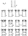
- FIG. 3 schematically shows the process sequence of the teaching according to the invention in order to introduce a door frame into a wall opening and to ensure quick mounting and fixing by means of the inflatable compensating elements and expansion elements according to the invention.
- the band-side compensation element is increasingly filled with air.
- the left cushion on the lock side is lowered (indicated by + or - sign in the area of the assembly cushion).
- a spreading element according to FIG. 2 is then introduced in the region of the transverse leg, the outer dimensions of which correspond to the nominal dimension of the distance between the longitudinal legs.
- the expansion element is - shown by the representation f), g) and h) - moved from the cross leg to the base.
- the lock-side leg is arranged on the nominal dimension to the hinge-side leg when the base point of the hinge-side leg remains immovable.
- the expansion element is then raised again, namely at the level of the lower band.
- the method according to the invention based on FIG. 3 reduces the installation time of a door frame in a wall opening by approximately 75% compared to known measures. This ensures that the reveal parts are aligned vertically in the final state without there being a risk of bulging, particularly during the foaming process. This is prevented by the expansion elements. At the same time, these have the effect that the force introduced vertically by the inflatable compensating elements is compensated to the extent that the reveal parts are not pushed through, that is, bulge inwards.
- the expansion element according to the invention can, however, not only be used as a setpoint setting and pressure compensation element for frame parts, but also wherever fixed distances from one another are to be maintained, for example between ceilings and floors, between carcass parts of furniture, between the reveal parts of windows and the like.
Landscapes
- Engineering & Computer Science (AREA)
- Architecture (AREA)
- Civil Engineering (AREA)
- Structural Engineering (AREA)
- Specific Sealing Or Ventilating Devices For Doors And Windows (AREA)
- Securing Of Glass Panes Or The Like (AREA)
Description
- Die Erfindung bezieht sich auf Verfahren zum Ausrichten eines in zum Beispiel eine Mauereinsparung einzubringenden Elementes wie Rahmen, Türzarge, Fensterzarge oder ähnliches, gemäß Oberbegriff der Ansprüche 1 und 3, sowie auf Vorrichtungen zur Durchführung dieser Verfahren gemäss Oberbegriff der Ansprüche 4 und 14.
- In der DE-A-2 260 856 ist eine Befestigungsvorrichtung für Bauelemente beschrieben. Um einen Fensterrahmen auszurichten, wirken zwei rechtwinklige zum Beispiel aus Metall bestehende Streifen miteinander zusammen, von denen der äußere fest mit dem Mauerwerk verbunden ist. Der innere Streifen ist zu dem äußeren um den Scheitelpunkt der Schenkel verschwenkbar. Der DE-A-3 022 936 ist ein Verfahren zum Ausrichten von Zargen zu entnehmen, bei dem Schläuche im Laibungsbereich einer Mauereinsparung angebracht werden, um ein Herunterlaufen des Schaumes zu verhindern.
- Aufgabe der Erfindung ist es mit einfachen Mitteln ein Element wie zum Beispiel einen Rahmen in eine insbesondere eine unregelmäßige Geometrie aufweisende Maueraussparung anzuordnen und derart zu fixieren, daß ein Befestigen des Elementes in der Maueraussparung möglich ist, ohne daß zu verwendende Hilfsmittel fest mit der Maueraussparung verbunden werden müssen.
- Diese Aufgabe wird durch die in den Ansprüchen 1 und 3 bzw. 4 und 14 beschriebenen Verfahren bzw. Vorrichtungen gelöst.
- Vorteilhafte Ausgestaltungen der Erfindung sind Gegenstand der Unteransprüche 2, 5 bis 13 und 15 bis 17.
- Durch das erfindungsgemäße Verfahren kann die Einbau- und Montagezeit einer Zarge auf etwa 15 Minuten reduziert werden, wobei dieser Zeitraum den Aushärtevorgang eines schnellhärtenden Schaumes von etwa 8 Minuten umfaßt. Mit anderen Worten ist der Zargenzusammenbau, das Einsetzen, das Fixieren, das Ausschäumen und das Bekleiden der Zarge in einem sehr kurzen Zeitraum durchführbar. Erkennbar ist dies mit leicht verrutschenden Keilen nach dem Stand der Technik nicht möglich. Optimal kann das Ausgleichselement im Zusammenhang mit den Spreizelementen, die zum kontrollierten Beabstanden der Zargenlängsschenkel, Laibungen oder ähnliches eingesetzt werden, dann erfolgen, wenn das Spreizelement zwei ineinandergreifende Innen- und Außenrohre mit an den zuzuordnenden Schenkeln abstützenden Endabschnitten umfaßt, wobei die Rohre aus Kunststoff bestehen können, das Außenrohr an dem dem Endabschnitt gegenüberliegenden Ende eine aufgesetzte Muffenmutter aufweist, dessen Innengewinde mit einer Außenfläche des Innenrohrs vorgesehenen Gewinde zusammenwirkt, und die Endabschnitte jeweils lösbar in dem zugehörigen Innen- bzw. Außenrohr angeordnet sind, wobei jedoch sichergestellt ist, daß ein Verkanten zueinander nicht möglich ist.
- Durch ein entsprechendes Abstandselement ist ein verrottungsfreies, den Abstand zwischen Laibungsteilen und ähnliches sicherndes Element zur Verfügung gestellt, das extrem leicht aufgebaut ist, ohne dadurch an Stabilität zu verlieren. Dabei kann das Außenrohr austauschbar sein, um beliebige Längen des Spreizelementes zur Verfügung zu stellen. Die Endabschnitte selbst können als Tellerpratzen ausgebildet sein, wobei ein Verkanten gegenüber den Rohren ausgeschlossen ist. Die Endabschnitte stellen demzufolge federnde Abschnitte dar. Die Muffenmutter mit ihrem Innengewinde ist vorzugsweise auf dem Außenrohr geklebt, so daß sich dadurch herstellungstechnisch und montagemäßig Vorteile ergeben. Die einzelnen Teile, die für ein solches Spreizelement erforderlich sind, können in Art eines Steckbausatzes zusammengefügt werden, wodurch für den Anwender selbst die Möglichkeit gegeben ist, Spreizelemente gewünschter Längen zusammenzubauen, sofern Außenrohre unterschiedlicher Längen zur Verfügung stehen.
- Weitere Einzelheiten, Vorteile und Merkmale ergeben sich aus den Ansprüchen.
- Nachstehend wird die Erfindung anhand von in der Zeichnung dargestellten bevorzugten Ausführungsbeispielen näher erläutert, wodurch sich weitere Einzelheiten, Vorteile und Merkmale ergeben.
- Es zeigen:
- Fig. 1 eine in eine Wandöffnung einzusetzende Türzarge,
- Fig. 2 ein Spreizelement und
- Fig. 3 eine Prinzipdarstellung des Montageablaufs für den Einbau einer Türzarge in eine Wandöffnung.
- In der Fig. 1 ist rein schematisch eine in eine Wandöffnung 10 einzusetzende Zarge 12 dargestellt, die Laibungen bzw. Türpfosten 14 und 16 sowie einen Querriegel 18 umfaßt. Zwischen der Zarge 12 und der Wandöffnung 10 besteht nun ein Freiraum, der mit aushärtendem Schaum ausgefüllt wird, um so die Zarge ortsfest anzuordnen. Zuvor ist es jedoch erforderlich, daß die Zarge richtig fixiert wird, also die gewünschte Position einnimmt, wozu nach dem Fixieren die Tür eingehängt wird, um festzustellen, ob die erforderliche Ausrichtung zur Vertikalen gegeben ist. Erfindungsgemäß wird in den oberen Eckbereichen zwischen Türzarge 12 und Wandöffnung 10 jeweils ein Ausgleichselement 20 bzw. 22 eingebracht, das als Lufttasche oder Luftmanschette ausgebildet ist. Diese Luftmanschette 20 bzw. 22 kann mittels eines Blasebalgs 24 bzw. 26, der auch als Aufblasballon bezeichnet werden kann, mit Luft beaufschlagt werden. In diesem Fall dehnt sich die Lufttasche 20 bzw. 22 aus, wobei sich eine Druckausbildung zwischen Wandöffnung 10 und Zarge 12, und zwar sowohl in vertikaler als auch in horizontaler Richtung ergibt. Dadurch ist sichergestellt, daß die Türpfosten 14 und 16 fest gegenüber dem Boden abgestützt sind, so daß ein ungewolltes Verrücken nicht mehr möglich ist. Die diesbezüglichen Verfahrensschritte werden im Zusammenhang mit Fig. 3 näher erläutert.
- Zwischen den Laibungsteilen 14 und 16 sind Spreizelemente 28 und 30 angeordnet, die nach einer weiteren Ausgestaltung der Erfindung jeweils aus einem hohlen Innenrohr 32 und einem hohlen Außenrohr 34 mit zwei Endabschnitten 36 und 38 sowie einer Muffenmutter 40 besteht. Die Muffenmutter 40 ist auf das Außenrohr 34 in dem dem Endabschnitt 36 gegenüberliegenden Bereich angeordnet. Dabei kann die Verbindung zwischen der Muffenmutter oder Überwurfmutter 40 und dem Außenrohr 34 durch Verkleben erfolgen. Alternativ können die Elemente durch genaue Passung gehalten werden. Der Innendurchmesser des Außenrohrs 34 ist dabei größer als der Flankendurchmesser des Innengewindes. Das Innengewinde 42 der Überwurfmutter 40 wirkt nun mit einem Außengewinde 44 zusammen, das in dem Innenrohr 32 eingelassen ist. Dabei kann das Außengewinde 44 vorzugsweise über die gesamte Länge des Innenrohrs 42 oder nur über einen äußeren dem Endabschnitt 36 abgewandten Bereich angeordnet sein.
- Die Endabschnitte 36 und 38 bestehen aus jeweils einem tellerförmigen äußeren Abschnitt 46 bzw. 48 und einem einen geringen Durchmesser aufweisenden Flanschansatz 50 bzw. 52, der dem Innendurchmesser des Innenrohrs 32 bzw. des Außenrohrs 34 angepaßt ist.
- Demzufolge erfolgt eine lösbare Verbindung zwischen dem Innenrohr 32 bzw. dem Außenrohr 34 und dem Endabschnitt 36 bzw. dem Endabschnitt 38. Trotz der lösbaren Verbindung ist sichergestellt, daß die Endabschnitte 36, 38 gegenüber dem Innen-und Außenrohr 32 bzw. 34 beim Festlegen zwischen zwei zu beabstandenden Elementen wie zum Beispiel Zargenteilen oder Laibungen nicht verkantet werden, so daß dadurch sichergestellt ist, daß die Elemente selbst den gewünschten durch den Abstand der Außenflächen der Endabschnitte 36 und 38 vorgegebenen Abstand zueinander aufweisen. Die Endabschnitte 36 und 38, die als Tellerpratzen zu bezeichnen sind, können ferner umlaufende elastische Ausgleichselemente 54 aufweisen, die sicherstellen, daß ein Ausgleich zwischen den freien Endflächen der Endabschnitte 36 und 38 und den angrenzenden Anlageflächen der zu beabstandenden Elemente gegeben ist. Die elastischen Ausgleichselemente 54 können als fächerförmig abragende elastische Elemente 56 ausgebildet sein, die - wie erwähnt - mit den Anlageflächen der Zargenteile und ähnliches zusammenwirken.
- Der dem umlaufenden abragenden Gummiabschnitt 56 gegenüberliegende Bereich 58 wird auf die tellerförmigen Abschnitte 46 und 48 aufgesetzt, um so eine sichere Verbindung zwischen den Elementen 54 und 36 bzw. 38 herzustellen.
- Sowohl das Innen- und Außenrohr 32 bzw. 34 als auch die Überwurfmutter 40 und die Tellerpratzen 36 und 38 sind aus Kunststoff hergestellt, so daß sich hieraus nicht nur herstellungs- und gewichtsmä- ßige Vorteile ergeben, ohne daß dadurch die Stabilität des Spreizelementes in Mitleidenschaft gezogen wird, sondern auch ein konstruktiv einfacher Aufbau zur Verfügung gestellt wird, der bei bekannten Türfutterstreben allein wegen der Verwendung verschiedener Materialien nicht gegeben ist.
- In der Fig. 3 ist schematisch der Verfahrensablauf der erfindungsgemäßen Lehre dargestellt, um eine Türzarge in eine Maueröffnung einzubringen und mittels der erfindungsgemäßen aufblasbaren Ausgleichselemente und Spreizelemente ein schnelles Montieren und Fixieren zu gewährleisten. Nachdem die Türzarge in die Maueraussparung eingebracht ist (a), werden die Ausgleichselemente wie Montagekissen in die oberen Eckbereiche eingebracht (b). Sodann werden die Ausgleichselemente gleichmäßig aufgepumpt, wodurch ein Ausfüllen des Zwischenraumes zwischen den Eckbereichen der Türzarge und der angrenzenden Wandöffnung erfolgt. Dabei wird gleichzeitig eine fluchtende Ausrichtung der schloßseitigen (linken) und wandseitigen (rechten) Zargenlaibung vorgenommen (c). Sodann wird der rechte Längsschenkel, also die bandseitige Laibung der Zarge, lotrecht ausgerichtet (d). Nach dem Verfahrensschritt d) wird das bandseitige Ausgleichselement verstärkt mit Luft gefüllt. Gleichzeitig erfolgt ein Ablassen des linken schloßseitigen Kissens (angedeutet durch + bzw. - Zeichen im Bereich der Montagekissen). Sodann wird im Bereich des Querschenkels ein Spreizelement gemäß Fig. 2 eingebracht, dessen Außenmaße dem Sollmaß des Abstandes der Längsschenkel entspricht. Das Spreizelement wird - durch die Darstellung f), g) und h) verdeutlicht - vom Querschenkel bis zu dem Fußpunkt verschoben. Dadurch wird der schloßseitige Schenkel bei unverrückbarem bodenseitigem Fußpunkt des bandseitigen Schenkels auf das Sollmaß zu dem bandseitigen Schenkel angeordnet. Gemäß Darstellung i) wird das Spreizelement sodann wieder angehoben, und zwar auf Höhe des unteren Bandes. Anschließend wird ein zweites Spreizelement eingebracht, das ebenfalls vom Querschenkel ausgehend bis in den Mittenbereich der Zarge verschoben wird (j, k). Sodann erfolgt eine Druckbeaufschlagung des schloßseitigen Montagekissens und ein Luftablassen des bandseitigen, und zwar in einem Umfang, daß die Längsschenkel lotrecht ausgerichtet sind. Sodann erfolgt eine gleichmässige Druckbeaufschlagung, um ein endgültiges Fixieren der Zarge zu gewährleisten, ohne daß die einzelnen Elemente noch verrücken (1). Schließlich wird die Tür in die Bänder eingehängt und der Zwischenraum zwischen Türzarge und Wandöffnung in bekannter Weise ausgeschäumt.
- Das anhand der Fig. 3 erfindungsgemäße Verfahren reduziert die Einbauzeit einer Türzarge in eine Wandöffnung gegenüber bekannten Maßnahmen um etwa 75%. Dabei ist gewährleistet, daß die Laibungsteile im Endzustand lotrecht ausgerichtet sind, ohne daß insbesondere während des Ausschäumens die Gefahr besteht, daß ein Ausbeulen erfolgt. Dies wird durch die Spreizelemente verhindert. Diese bewirken gleichzeitig, daß die von den aufblasbaren Ausgleichselementen vertikal eingebrachte Kraft in dem Umfang kompensiert wird, daß die Laibungsteile nicht durchgedrückt werden, also sich nach innen ausbeulen.
- Das erfindungsgemäße Spreizelement kann jedoch nicht nur als Sollmaßeinstellung und Druckausgleichselement für Zargenteile benutzt werden, sondern überall dort, wo feste Abstände zueinander eingehalten werden sollen, so zum Beispiel zwischen Decken und Böden, zwischen Korpusteilen von Möbeln, zwischen den Laibungsteilen von Fenstern und ähnliches.
Claims (18)
Priority Applications (1)
| Application Number | Priority Date | Filing Date | Title |
|---|---|---|---|
| AT85900103T ATE42796T1 (de) | 1983-12-08 | 1984-12-10 | Verfahren und vorrichtung zum ausrichten eines in zum beispiel eine maueraussparung einzubringenden elementes wie rahmen. |
Applications Claiming Priority (4)
| Application Number | Priority Date | Filing Date | Title |
|---|---|---|---|
| DE8335189U | 1983-12-08 | ||
| DE19838335189 DE8335189U1 (de) | 1983-12-08 | 1983-12-08 | Spreizelement |
| DE19848406973U DE8406973U1 (de) | 1984-03-07 | 1984-03-07 | Ausgleichselement fuer eine zarge |
| DE8406973U | 1984-03-07 |
Publications (2)
| Publication Number | Publication Date |
|---|---|
| EP0193531A1 EP0193531A1 (de) | 1986-09-10 |
| EP0193531B1 true EP0193531B1 (de) | 1989-05-03 |
Family
ID=25949720
Family Applications (1)
| Application Number | Title | Priority Date | Filing Date |
|---|---|---|---|
| EP85900103A Expired EP0193531B1 (de) | 1983-12-08 | 1984-12-10 | Verfahren und vorrichtung zum ausrichten eines in zum beispiel eine maueraussparung einzubringenden elementes wie rahmen |
Country Status (4)
| Country | Link |
|---|---|
| US (1) | US4679373A (de) |
| EP (1) | EP0193531B1 (de) |
| DE (1) | DE3478043D1 (de) |
| WO (1) | WO1985002648A1 (de) |
Cited By (1)
| Publication number | Priority date | Publication date | Assignee | Title |
|---|---|---|---|---|
| DE10028439A1 (de) * | 2000-06-14 | 2002-01-03 | Bernd Ludwig | Anordnung eines Rahmens in eine Wand sowie Verfahren zum Anordnen eines solchen |
Families Citing this family (11)
| Publication number | Priority date | Publication date | Assignee | Title |
|---|---|---|---|---|
| DK127593D0 (da) * | 1993-11-10 | 1993-11-10 | Mogens Laurits Jensen | Fremgangsmaade og hjaelpevaerktoej til montering af bygningsdele saasom vindueskarme i monteringsaabninger |
| DE29717506U1 (de) | 1997-09-22 | 1999-01-28 | Ludwig, Bernd, 63517 Rodenbach | Montageeinrichtung |
| US6651394B2 (en) * | 2000-04-24 | 2003-11-25 | Bill Hughes | Apparatus for use in the construction of precast, moment-resisting frame buildings |
| US6701672B2 (en) * | 2001-04-30 | 2004-03-09 | Kohler Co. | Compression mounting system for shower doors |
| US8302353B2 (en) * | 2004-10-15 | 2012-11-06 | Thomas Bren | Water intrusion prevention method and apparatus |
| DE102005056489B4 (de) * | 2005-11-21 | 2010-10-14 | Gollwitzer, Karl | Verfahren zum Einbau eines Gebäudeabschlusselements |
| IT1395387B1 (it) * | 2009-08-31 | 2012-09-14 | Hesperia S A S Di Donato Franco & C | Controtelaio per porte e finestre ed elementi distanziali per controtelaio |
| KR101288815B1 (ko) * | 2012-10-26 | 2013-07-23 | 한국건설기술연구원 | 사춤재, 창호 및 사춤방법 |
| DK178296B1 (da) * | 2014-08-08 | 2015-11-09 | Dissing As | Hjælpeværktøj til brug ved placering af elementer i forhold til en tilstødende flade |
| EP3206985B1 (de) * | 2014-10-13 | 2021-12-22 | Dissing A/S | Vorrichtung zum positionieren eines elements relativ zu einer oberfläche, verfahren zum betrieb solch einer vorrichtung, und bausatz dafür |
| CN111706217A (zh) * | 2020-06-05 | 2020-09-25 | 广西建工集团冶金建设有限公司 | 一种利用渐变可控式气囊调节安装铝合金窗的施工方法 |
Family Cites Families (8)
| Publication number | Priority date | Publication date | Assignee | Title |
|---|---|---|---|---|
| US2960734A (en) * | 1958-08-29 | 1960-11-22 | David R Collins | Compensating means |
| DE1509913A1 (de) * | 1965-11-16 | 1969-06-26 | Peter Schaefges | Montagegeraet fuer Stahlzargen |
| US3571996A (en) * | 1969-04-07 | 1971-03-23 | Mesker Brothers Ind Inc | Doorframe |
| US3854253A (en) * | 1972-05-01 | 1974-12-17 | J Slowbe | Joint construction between supported and supporting members |
| DE2260856A1 (de) * | 1972-12-13 | 1974-06-20 | Friedrich Klein | Befestigungsvorrichtung fuer bauelemente |
| DE2520632A1 (de) * | 1975-05-09 | 1976-11-18 | Hermann Ing Grad Heinrich | Variable einbaulehre mit selbsthalterung durch elastisches element |
| DE2617169A1 (de) * | 1976-04-20 | 1977-11-10 | Willi Herrig | Verfahren zum befestigen eines gegenstandes in einer in einem anderen gegenstand befindlichen oeffnung sowie nach diesem verfahren zu befestigenden gegenstand |
| DE3022936A1 (de) * | 1980-06-19 | 1981-12-24 | Hilti AG, 9494 Schaan | Verfahren zum ausrichten von zargen |
-
1984
- 1984-12-10 EP EP85900103A patent/EP0193531B1/de not_active Expired
- 1984-12-10 WO PCT/EP1984/000395 patent/WO1985002648A1/de not_active Ceased
- 1984-12-10 US US06/767,199 patent/US4679373A/en not_active Expired - Lifetime
- 1984-12-10 DE DE8585900103T patent/DE3478043D1/de not_active Expired
Cited By (2)
| Publication number | Priority date | Publication date | Assignee | Title |
|---|---|---|---|---|
| DE10028439A1 (de) * | 2000-06-14 | 2002-01-03 | Bernd Ludwig | Anordnung eines Rahmens in eine Wand sowie Verfahren zum Anordnen eines solchen |
| DE10028439B4 (de) * | 2000-06-14 | 2008-01-10 | Bernd Ludwig | Anordnung eines Rahmens in eine Wand sowie Verfahren zum Anordnen eines solchen |
Also Published As
| Publication number | Publication date |
|---|---|
| US4679373A (en) | 1987-07-14 |
| EP0193531A1 (de) | 1986-09-10 |
| DE3478043D1 (en) | 1989-06-08 |
| WO1985002648A1 (fr) | 1985-06-20 |
Similar Documents
| Publication | Publication Date | Title |
|---|---|---|
| DE10338816B3 (de) | Halterung für eine Platte, insbesondere für eine Glasscheibe | |
| WO1985002648A1 (fr) | Procede et installation pour aligner un element, comme un cadre, a introduire par exemple dans un evidement de mur | |
| DE2617169A1 (de) | Verfahren zum befestigen eines gegenstandes in einer in einem anderen gegenstand befindlichen oeffnung sowie nach diesem verfahren zu befestigenden gegenstand | |
| DE2210988A1 (de) | Verfahren und geraet zum verbauen von baugruben | |
| DE9013588U1 (de) | Installationsbaustein für Sanitäreinrichtungen | |
| DE102009044421B4 (de) | Verstellbare Justierschiene | |
| DE3036791A1 (de) | Einrichtung zum schliessen einer oeffnung, insbesondere eines fensters oder einer tuere in einem rohbau | |
| WO2016162154A1 (de) | Verfahren zur herstellung von verklotzungen von fenstern | |
| AT508760B1 (de) | Verstellbare justierschiene | |
| WO2011054721A1 (de) | Verstellbare justierschiene | |
| DE3022936A1 (de) | Verfahren zum ausrichten von zargen | |
| DE102005061133B3 (de) | Montagevorrichtung für eine Duschabtrennung und Verfahren zur Verwendung einer derartigen Montagevorrichtung | |
| DE29717506U1 (de) | Montageeinrichtung | |
| EP1103667A2 (de) | Hilfsvorrichtung zur Halterung von Randisolierungen | |
| DE1709048B1 (de) | Vorrichtung zum Befestigen eines Halters fuer eine Dachrandeinfassung | |
| DE9102282U1 (de) | Anschlaggestell | |
| DE8406973U1 (de) | Ausgleichselement fuer eine zarge | |
| EP1579094A1 (de) | Fassadenelement, verfahren zur herstellung des fassadenelements sowie fassadensystem | |
| DE8304353U1 (de) | Traeger fuer eine rollschicht eines mauerwerks | |
| DE4228179A1 (de) | Vorrichtung zum Abdichten von Schlitzwandfugen sowie Verfahren zu ihrer Anwendung | |
| DE1160161B (de) | Umfassungszarge fuer Tueren | |
| AT403716B (de) | Schalung für die herstellung einer leistenförmigen betonnase | |
| EP0376046B1 (de) | Verfahren zum Einbau einer Wanne und Wanne, insbesondere zur Verwendung bei dem Verfahren | |
| DE19942875C2 (de) | Montagevorrichtung für Fensterbretter sowie ein Verfahren zu dessen Verwendung | |
| DE69916539T2 (de) | Verfahren zum Herstellen einer Fassadenplatte und Anordnung von Verbindungsabschnitten für dieses Verfahren |
Legal Events
| Date | Code | Title | Description |
|---|---|---|---|
| PUAI | Public reference made under article 153(3) epc to a published international application that has entered the european phase |
Free format text: ORIGINAL CODE: 0009012 |
|
| 17P | Request for examination filed |
Effective date: 19860609 |
|
| AK | Designated contracting states |
Kind code of ref document: A1 Designated state(s): AT BE CH DE FR GB LI LU NL SE |
|
| 17Q | First examination report despatched |
Effective date: 19870903 |
|
| GRAA | (expected) grant |
Free format text: ORIGINAL CODE: 0009210 |
|
| AK | Designated contracting states |
Kind code of ref document: B1 Designated state(s): AT BE CH DE FR GB LI LU NL SE |
|
| REF | Corresponds to: |
Ref document number: 42796 Country of ref document: AT Date of ref document: 19890515 Kind code of ref document: T |
|
| REF | Corresponds to: |
Ref document number: 3478043 Country of ref document: DE Date of ref document: 19890608 |
|
| GBT | Gb: translation of ep patent filed (gb section 77(6)(a)/1977) | ||
| ET | Fr: translation filed | ||
| PLBE | No opposition filed within time limit |
Free format text: ORIGINAL CODE: 0009261 |
|
| STAA | Information on the status of an ep patent application or granted ep patent |
Free format text: STATUS: NO OPPOSITION FILED WITHIN TIME LIMIT |
|
| 26N | No opposition filed | ||
| EPTA | Lu: last paid annual fee | ||
| EAL | Se: european patent in force in sweden |
Ref document number: 85900103.4 |
|
| PGFP | Annual fee paid to national office [announced via postgrant information from national office to epo] |
Ref country code: GB Payment date: 19981211 Year of fee payment: 15 |
|
| PGFP | Annual fee paid to national office [announced via postgrant information from national office to epo] |
Ref country code: BE Payment date: 19981224 Year of fee payment: 15 |
|
| PGFP | Annual fee paid to national office [announced via postgrant information from national office to epo] |
Ref country code: SE Payment date: 19981230 Year of fee payment: 15 Ref country code: FR Payment date: 19981230 Year of fee payment: 15 |
|
| PGFP | Annual fee paid to national office [announced via postgrant information from national office to epo] |
Ref country code: NL Payment date: 19981231 Year of fee payment: 15 |
|
| PGFP | Annual fee paid to national office [announced via postgrant information from national office to epo] |
Ref country code: LU Payment date: 19990107 Year of fee payment: 15 |
|
| PG25 | Lapsed in a contracting state [announced via postgrant information from national office to epo] |
Ref country code: LU Free format text: LAPSE BECAUSE OF NON-PAYMENT OF DUE FEES Effective date: 19991210 Ref country code: GB Free format text: LAPSE BECAUSE OF NON-PAYMENT OF DUE FEES Effective date: 19991210 |
|
| PG25 | Lapsed in a contracting state [announced via postgrant information from national office to epo] |
Ref country code: SE Free format text: LAPSE BECAUSE OF NON-PAYMENT OF DUE FEES Effective date: 19991211 |
|
| PG25 | Lapsed in a contracting state [announced via postgrant information from national office to epo] |
Ref country code: BE Free format text: LAPSE BECAUSE OF NON-PAYMENT OF DUE FEES Effective date: 19991231 |
|
| PGFP | Annual fee paid to national office [announced via postgrant information from national office to epo] |
Ref country code: DE Payment date: 20000128 Year of fee payment: 16 |
|
| BERE | Be: lapsed |
Owner name: LUDWIG BERND Effective date: 19991231 |
|
| PG25 | Lapsed in a contracting state [announced via postgrant information from national office to epo] |
Ref country code: NL Free format text: LAPSE BECAUSE OF NON-PAYMENT OF DUE FEES Effective date: 20000701 |
|
| GBPC | Gb: european patent ceased through non-payment of renewal fee |
Effective date: 19991210 |
|
| EUG | Se: european patent has lapsed |
Ref document number: 85900103.4 |
|
| PG25 | Lapsed in a contracting state [announced via postgrant information from national office to epo] |
Ref country code: FR Free format text: LAPSE BECAUSE OF NON-PAYMENT OF DUE FEES Effective date: 20000831 |
|
| NLV4 | Nl: lapsed or anulled due to non-payment of the annual fee |
Effective date: 20000701 |
|
| REG | Reference to a national code |
Ref country code: FR Ref legal event code: ST |
|
| PGFP | Annual fee paid to national office [announced via postgrant information from national office to epo] |
Ref country code: AT Payment date: 20001229 Year of fee payment: 17 |
|
| PGFP | Annual fee paid to national office [announced via postgrant information from national office to epo] |
Ref country code: CH Payment date: 20010206 Year of fee payment: 17 |
|
| PG25 | Lapsed in a contracting state [announced via postgrant information from national office to epo] |
Ref country code: DE Free format text: LAPSE BECAUSE OF NON-PAYMENT OF DUE FEES Effective date: 20010702 |
|
| PG25 | Lapsed in a contracting state [announced via postgrant information from national office to epo] |
Ref country code: AT Free format text: LAPSE BECAUSE OF NON-PAYMENT OF DUE FEES Effective date: 20011210 |
|
| PG25 | Lapsed in a contracting state [announced via postgrant information from national office to epo] |
Ref country code: LI Free format text: LAPSE BECAUSE OF NON-PAYMENT OF DUE FEES Effective date: 20011231 Ref country code: CH Free format text: LAPSE BECAUSE OF NON-PAYMENT OF DUE FEES Effective date: 20011231 |
|
| REG | Reference to a national code |
Ref country code: CH Ref legal event code: PL |