EP0193290B1 - Fluid flow rate monitor probe - Google Patents
Fluid flow rate monitor probe Download PDFInfo
- Publication number
- EP0193290B1 EP0193290B1 EP86300725A EP86300725A EP0193290B1 EP 0193290 B1 EP0193290 B1 EP 0193290B1 EP 86300725 A EP86300725 A EP 86300725A EP 86300725 A EP86300725 A EP 86300725A EP 0193290 B1 EP0193290 B1 EP 0193290B1
- Authority
- EP
- European Patent Office
- Prior art keywords
- port
- face
- flow
- probe
- tip portion
- Prior art date
- Legal status (The legal status is an assumption and is not a legal conclusion. Google has not performed a legal analysis and makes no representation as to the accuracy of the status listed.)
- Expired
Links
- 239000000523 sample Substances 0.000 title claims description 52
- 239000012530 fluid Substances 0.000 title claims description 12
- 238000000926 separation method Methods 0.000 claims description 16
- 238000011144 upstream manufacturing Methods 0.000 claims description 9
- 238000012544 monitoring process Methods 0.000 claims description 6
- 230000001419 dependent effect Effects 0.000 claims description 3
- 239000007789 gas Substances 0.000 description 12
- 238000010079 rubber tapping Methods 0.000 description 10
- 230000004048 modification Effects 0.000 description 7
- 238000012986 modification Methods 0.000 description 7
- 210000003414 extremity Anatomy 0.000 description 6
- VNWKTOKETHGBQD-UHFFFAOYSA-N methane Chemical compound C VNWKTOKETHGBQD-UHFFFAOYSA-N 0.000 description 6
- 238000005219 brazing Methods 0.000 description 4
- 230000003068 static effect Effects 0.000 description 4
- 238000010276 construction Methods 0.000 description 3
- 238000003754 machining Methods 0.000 description 3
- 239000003345 natural gas Substances 0.000 description 3
- 229910001369 Brass Inorganic materials 0.000 description 2
- 239000010951 brass Substances 0.000 description 2
- 230000008878 coupling Effects 0.000 description 2
- 238000010168 coupling process Methods 0.000 description 2
- 238000005859 coupling reaction Methods 0.000 description 2
- 229910001220 stainless steel Inorganic materials 0.000 description 2
- 239000010935 stainless steel Substances 0.000 description 2
- 238000013459 approach Methods 0.000 description 1
- 239000000428 dust Substances 0.000 description 1
- 230000000694 effects Effects 0.000 description 1
- 230000008030 elimination Effects 0.000 description 1
- 238000003379 elimination reaction Methods 0.000 description 1
- 238000002474 experimental method Methods 0.000 description 1
- 210000004907 gland Anatomy 0.000 description 1
- 238000009434 installation Methods 0.000 description 1
- 239000007788 liquid Substances 0.000 description 1
- 210000003141 lower extremity Anatomy 0.000 description 1
- 239000000203 mixture Substances 0.000 description 1
- 239000013618 particulate matter Substances 0.000 description 1
- 238000011084 recovery Methods 0.000 description 1
- 239000007787 solid Substances 0.000 description 1
Images

Classifications
-
- G—PHYSICS
- G01—MEASURING; TESTING
- G01F—MEASURING VOLUME, VOLUME FLOW, MASS FLOW OR LIQUID LEVEL; METERING BY VOLUME
- G01F1/00—Measuring the volume flow or mass flow of fluid or fluent solid material wherein the fluid passes through a meter in a continuous flow
- G01F1/05—Measuring the volume flow or mass flow of fluid or fluent solid material wherein the fluid passes through a meter in a continuous flow by using mechanical effects
- G01F1/34—Measuring the volume flow or mass flow of fluid or fluent solid material wherein the fluid passes through a meter in a continuous flow by using mechanical effects by measuring pressure or differential pressure
- G01F1/36—Measuring the volume flow or mass flow of fluid or fluent solid material wherein the fluid passes through a meter in a continuous flow by using mechanical effects by measuring pressure or differential pressure the pressure or differential pressure being created by the use of flow constriction
- G01F1/40—Details of construction of the flow constriction devices
- G01F1/46—Pitot tubes
Definitions
- the invention relates to probes for use in monitoring flow rate in fluids.
- the invention particularly, though not exclusively, relates to such probes used for monitoring the flow rate of natural gas in distribution pipes.
- a well-known kind of probe is the so-called Pitot-static tube.
- Such a tube is L-shaped and has a lower end portion extending parallel to the direction of the monitored flow.
- the tip of the end portion is presented towards the oncoming flow and has a first sensing port the plane of which is transverse to the monitored flow.
- a second sensing port, or each one of an array of second ports, is provided downstream of the first port in the wall of the end portion.
- the plane of the, or of each, second port is parallel to that monitored flow.
- the difference between the pressures at the first and second ports is proportional to the square of the velocity of the fluid at the tip.
- the object of the invention is to provide a probe having a sensing port but which avoids the need for two such edges.
- United States specification No. US-A 3 702 566 describes a hot-wire anemometer. It has an elongate body and tip portion. There is a through-passage in the tip postion. There are two passages in the body, which both open into the through-passage. However, the two passages are fluid flow passages leading to a pitot tube and a pitot probe. Ther is no effective edge in the through-passage and no vena contracta. There is no sensing of the pressure adjacent the edge by means of a port opening in the bounding surface of the through-passage.
- a withdrawable probe for use in monitoring fluid flow rate in combination with apparatus responsive to a difference between two sensed pressures at least one of which is sensed at a port provided in the probe, the probe comprises an elongate body including a tip portion having a surface intersecting the upstream and downstream sides of the tip portion and the intersection at the upstream side forming an edge which extends transversely to the direction of the monitored flow, said port opening in said surface and is characterized in that the edge is effective to cause flow separation of fluid from said surface downstream of said edge, said port facing transversely to said direction of monitored flow or inclined thereto to face downstream in relation to said direction, said port being located where flow-separation occurs adjacent said edge and the sensed pressure at said port being the lower of said two sensed pressures.
- the surface is at the extremity of the lip portion.
- the surface is a bounding surface of a passage extending through the tip portion.
- the bounding surface entirely surrounds a vena contracta caused by said flow-separation, the edge, for example, being a circular edge.
- the surface is at the extremity of the tip portion and the passage is channel-shaped and only partly encloses the flow through the passage, the edge being for example semi-circular, or V-shaped or U-shaped with a flat or curved base.
- a second sensing port is provided which opens at the wall of the pipe or conduit confining the monitored flow.
- the second port is provided on the tip portion, the second port facing transversely to the direction of the monitored flow and the second port being positioned adjacent the upstream side of the tip portion with respect to said direction.
- the tip portion is of stepped shape defined by two faces, the first of which is presented towards the oncoming monitored flow and the second of which is normal to that face, the second port opening in the second face adjacent the first face.
- the first face is either plane or preferably concave and part cylindrical, having an axis of curvature parallel to the longitudinal central axis of the body.
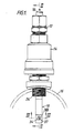
- the probe comprises an elongate, cylindrical body made up of a stainless steel tube 10 joined by brazing at its upper end to a brass T-shaped connector body (not shown) and joined at its lower end to a tip portion 18 described below.
- the tube 10 extends through a coupling 12 and ball valve 14.
- the valve 14 is fitted at its lower end into a circular hole in the wall of a distribution pipe 16 through which natural gas flows.
- the lower end of the tube 10 is joined by brazing to the brass tip portion 18.
- Two stainless steel tubes 20, 22 extend through the tube 10 and their lower ends are received in bores in the upper end of the portion 18 and are joined to the portion by brazing.
- the upper ends of the tubes 20, 22 are received in bores in the T-connection body (not shown) and are joined by brazing to the body.
- the tip portion 18 is machined from solid rod, typically in this example of 0.5 inch (12.7 millimetre) outside diameter. Beneath the lower end of the tube 10 and beneath the lower end of the spigot 24 of the valve 14, the portion 18 is machined at the upstream side with respect to the direction of gas flow in the pipe 16 indicated by the arrow to form stepped shape defined by a downwardly presented horizontal face 26, extending parallel to the flow direction.
- the machining of the portion 18 leaves a concave face 28 further defining the stepped shape.
- the centre of curvature of the face 28 is at 30, the face 28 thus being part of the inner surface of a notional hollow right cylinder having a vertical central axis of symmetry at 30 and having a radius of 12mm, for example.
- the machining leaves a plane vertical face at 32 beneath the lower end of the face 28.
- the face 32 extends downwardly to the lower extremity of the portion 18.
- a circular horizontal hole is drilled through the portion 18 to form a through-passage 34 having a surface and with a sharp leading circular edge 35 defining an entrance at the face 32 and a sharp-edged exit at the cylindrical downstream surface of the portion 18. It is preferred, as shown, for the central axis of the passage 34 to coincide with the central axis 37 of the pipe 16.
- the passage 34 thus extends parallel to the direction of monitored flow in the pipe 16.
- the diameter of the passage 34 is 6mm.
- the first tapping 36 opens at its upper end into the tube 20 and at its lower end opens at a sensing port 38 in the upper part of the surface 33 of the through-passage 34.
- the sharp leading edge 35 of the passage 34 causes flow-separation of the gas away from the surface 33 of the passage 34 and a vena contracta is formed within the passage 34.
- the port 38 is positioned so as to be at the flow-separation around the vena contracta.
- the port 38 is preferably positioned as shown in Figure 3 slightly nearer to the face 32 than to the convex downstream side of the portion 18 so that the pressure sensed at the port 38 is as low as possible.
- the optimum positioning of the port 38 and the optimum size of the through-passage 34 cannot be precisely stipulated but can be readily checked experimentally.
- the second tapping 40 opens at its upper end into the tube 22 and at its lower end at a sensing port 42 in the face 26.
- the port 42 is closely adjacent the upper end of the concave face 28.
- the T-connection (not shown) is connected by couplings to small diameter tubing leading to a differential pilot valve, for example a pilot valve of high gain type forming part of a system by which pressure in the pipe 16 can be related to the flow through the pipe.
- the probe in such a case is located downstream of a governor valve the setting of which is controlled byoperation of the high gain pilot valve.
- the probe can be connected in other systems (not shown) to a different component, such as a manometer gauge or other device.
- the pressure at the port 38 is less than the static pressure of the gas in the pipe 16. It has been found in the case of the example of construction described above that the pressure at the port 38 is less than the static pressure by an amount equal to twice the dynamic pressure, owing to the effect of the flow-separation of the gas away from the surface 33 of the passage 34 around the vena contracta.
- the concave face 28 is effective to produce a stagnation zone immediately upstream of the face 28 and at the port 42 in which zone the pressure is higher than the static pressure by an amount equal to the dynamic pressure.
- the difference between the pressures at the two ports 38,42 is equal to three times the dynamic pressure, alternatively referred to as the velocity head.
- Changes in the mean rate of flow of gas through the pipe 16 are readily monitored since the pressure sensed at the port 38 or 42 is dependent on the square of the velocity of the gas which approaches the port 38 or which passes the port 42, respectively.
- the convex form of the downstream side of the portion 18 facilitates flow to maintain high velocity past the probe and through the hole 34.
- the face 28 is plane instead of concave. Some reduction of the pressure differences available from the probe will probably result.
- the curved face is preferred also because the pressure difference is unaffected by slight errors in angular orientation of the probe about its central longitudinal axis, which may arise during fitting to the pipe 16.
- the port 42, the tapping 40 and the tube 22 are dispensed with or not used. Instead, the static pressure of the gas flow is sensed by a port provided by a tapping in the wall of the pipe 16, eg upstream of the probe. In that case the pressure difference available between the tapping port and the port 38 would be reduced to a value equal to some two times the dynamic pressure. However, the other advantages of the probe would remain unaffected.
- the size of the hole 34 was found by experiment in order to give satisfactory results.
- the same size of probe is applicable to pipes up to at least 12 inches (300mm) inside diameter.
- the size of the hole may be different from that specified above, subject to the requirement that a flow-separation occurs, in use, giving a pressure low enough to be useful.
- one of the tubes 20, 22 is dispensed with, the respective sensing port communicating with the T-connection via the interior of the tube 10.
- the tip portion 18 is stepped as described above but the face 28 extends right to the extremity of the tip portion 18 or nearly to the extremity and the step shape is positioned between the extremity and the through-passage, which typically, for example, is a circular hole similar to the hole 34 but extending through the full diameter of the portion 18.
- the face 28 conveniently has an axis of curvature offset from the central plane 50 shown in Figure 3 so that the tapping and the port (corresponding to the port 42) are also offset so that the tapping avoids the through-passage.
- the through-passage has a pressure-recovery section at its downstream end.
- a modification enhances the velocity of flow through the passage by reducing the effective resistance presented by the passage. This can increase the total pressure differential available from the probe up to some six times the dynamic pressure.
- the through-passage in such a case is a circular hole having a section at its downstream end which is conically divergent in the direction of fluid flow.
- the through-passage is formed at the extremity of the tip portion 18, for example by machining a channel in the end wall of the tip portion, extending lengthwise in the direction of the monitored flow.
- the end wall is a plane wall normal to the length of the body and the transverse cross-section of the channel is semi-circular, or V-shaped or U-shaped, with a flat or curved base.
- the leading edge of the channel (with respect to the flow direction) is such as to cause flow-separation of the gas away from the wall or walls of the channel, ie the leading edge is sufficiently sharp, for example, to produce the necessary flow-separation.
- a partial vena contracta is formed in the channel.
- the sensing port corresponding to the port 38 is positioned at or adjacent the position of maximum pressure depression caused by the flow-separation.
- the tip portion 18 is devoid of any through-passage and the leading edge of the end wall of the portion causes flow-separation from the end wall.
- a sensing port in the wall is positioned at the flow separation and at or adjacent the position of maximum pressure depression caused by the flow-separation.
- the end wall is either normal to the length of the body so that the port is parallel to the general direction of monitored flow or the wall is inclined to that direction so that the port is inclined and faces downstream in relation to that general direction.
- the probe is applicable to monitoring flow of gases other than natural gas and to monitoring flows of liquids and fluid mixtures, including steam, for example.
Landscapes
- Physics & Mathematics (AREA)
- Fluid Mechanics (AREA)
- General Physics & Mathematics (AREA)
- Measuring Volume Flow (AREA)
- Branch Pipes, Bends, And The Like (AREA)
Applications Claiming Priority (2)
| Application Number | Priority Date | Filing Date | Title |
|---|---|---|---|
| GB08505092A GB2171526B (en) | 1985-02-27 | 1985-02-27 | Fluid flow rake monitor probe |
| GB8505092 | 1985-02-27 |
Publications (3)
| Publication Number | Publication Date |
|---|---|
| EP0193290A2 EP0193290A2 (en) | 1986-09-03 |
| EP0193290A3 EP0193290A3 (en) | 1987-09-09 |
| EP0193290B1 true EP0193290B1 (en) | 1989-10-25 |
Family
ID=10575187
Family Applications (1)
| Application Number | Title | Priority Date | Filing Date |
|---|---|---|---|
| EP86300725A Expired EP0193290B1 (en) | 1985-02-27 | 1986-02-04 | Fluid flow rate monitor probe |
Country Status (5)
| Country | Link |
|---|---|
| US (1) | US4719806A (ja) |
| EP (1) | EP0193290B1 (ja) |
| JP (1) | JPH0752111B2 (ja) |
| DE (1) | DE3666628D1 (ja) |
| GB (1) | GB2171526B (ja) |
Families Citing this family (19)
| Publication number | Priority date | Publication date | Assignee | Title |
|---|---|---|---|---|
| JPS63158415A (ja) * | 1986-12-23 | 1988-07-01 | Yokokawa Nabitetsuku Kk | 流体の物理量検知装置 |
| GB2231667B (en) * | 1989-05-08 | 1992-11-18 | Rosemount Ltd | Deployable probe |
| GB9105699D0 (en) * | 1991-03-18 | 1991-05-01 | British Gas Plc | Supplying fluid |
| US5442958A (en) * | 1992-12-15 | 1995-08-22 | The B.F. Goodrich Company | Deployable probe combined with flush static port |
| DE4417913C1 (de) * | 1994-05-21 | 1995-09-21 | Bundesrep Deutschland | Gasströmungssonde |
| US6591695B1 (en) * | 1996-05-07 | 2003-07-15 | Efg & E International | Flow metering device for landfill gas extraction well |
| US6917886B2 (en) * | 2000-11-06 | 2005-07-12 | Adam Cohen | Microflow based differential pressure sensor |
| US7798017B2 (en) * | 2005-07-14 | 2010-09-21 | Systec Controls Mess-Und Regelungstechnik Gmbh | Ram pressure probe having two ducts and a differential pressure increasing element |
| US20110179650A1 (en) * | 2010-01-25 | 2011-07-28 | William Farrell | Pill Card Bubble Cutter |
| US9285288B2 (en) * | 2013-09-26 | 2016-03-15 | Dieterich Standard, Inc. | Retractable flow conditioner |
| US9996089B2 (en) * | 2015-09-21 | 2018-06-12 | Blue-White Industries, Ltd. | Flow sensor devices and systems |
| US10288461B2 (en) * | 2016-02-29 | 2019-05-14 | Mueller International, Llc | Piezoelectric cable flow sensor |
| US11150118B2 (en) * | 2016-09-23 | 2021-10-19 | Blue-White Industries, Ltd. | Flow sensor devices and systems |
| US11400328B2 (en) | 2019-06-07 | 2022-08-02 | Mueller International, Llc | Hydrant monitoring communications hub |
| US10934693B2 (en) | 2019-06-07 | 2021-03-02 | Mueller International, Llc | Hydrant monitoring system |
| US11639863B2 (en) | 2019-06-07 | 2023-05-02 | Blue-White Industries, Ltd. | Flow sensor devices and systems |
| US10968609B2 (en) | 2019-06-07 | 2021-04-06 | Mueller International, Llc | Self-contained hydrant monitoring system |
| US10941545B2 (en) | 2019-06-07 | 2021-03-09 | Mueller International, Llc | Hydrant monitoring system |
| CN114714106B (zh) * | 2022-04-11 | 2023-04-21 | 中车青岛四方机车车辆股份有限公司 | 差压阀铜管管支架定位工装及轨道车辆构架管路组装方法 |
Family Cites Families (25)
| Publication number | Priority date | Publication date | Assignee | Title |
|---|---|---|---|---|
| US2704555A (en) * | 1955-03-22 | Low loss venturi tube | ||
| US790888A (en) * | 1901-03-18 | 1905-05-30 | Walter Ferris | Fluid-meter. |
| US1089129A (en) * | 1912-04-22 | 1914-03-03 | Egbert U Havill | Pitometer. |
| GB191221864A (en) * | 1912-09-25 | 1913-08-07 | British Thomson Houston Co Ltd | Improvements in and relating to Nozzle Plugs for Fluid Flow Meters. |
| GB345839A (en) * | 1930-04-15 | 1931-04-02 | Frederick Mackman Watson | Improvements in devices for creating pressure difference in fluid conduits |
| US1980672A (en) * | 1930-12-02 | 1934-11-13 | Republic Flow Meters Co | Orifice plate for flow meters |
| US2127501A (en) * | 1935-12-28 | 1938-08-23 | Leeds And Northurp Company | Fluid flow measuring means |
| DE920527C (de) * | 1940-10-11 | 1954-11-25 | Kurt Prange Dr | Gegenhalter zum Nieten von Bauteilen, insbesondere Hohlkoerpern |
| US2842962A (en) * | 1953-10-29 | 1958-07-15 | Kent Ltd G | Pressure differential producing device |
| US3349615A (en) * | 1964-10-30 | 1967-10-31 | Charles W Finkl | Marine speed indicators |
| US3559482A (en) * | 1968-11-27 | 1971-02-02 | Teledyne Inc | Fluid flow measuring apparatus |
| US3688576A (en) * | 1970-07-24 | 1972-09-05 | Illinois Testing Laboratories | Improved air velocity measuring system and method for its calibration |
| US3683693A (en) * | 1970-10-08 | 1972-08-15 | William R Brown | Universal proportional differential pressure producing fluid flow device |
| US3702566A (en) * | 1970-10-16 | 1972-11-14 | Illinois Testing Laboratories | High air velocity measuring system having thermotransducer |
| US3719082A (en) * | 1971-03-29 | 1973-03-06 | Alnor Instr Co | Air velocity measuring system |
| US3759098A (en) * | 1972-01-27 | 1973-09-18 | Aeronca Inc | Apparatus for determining fluid flow in a conduit |
| US3889536A (en) * | 1973-03-29 | 1975-06-17 | Wehr Corp | Flow measuring and monitoring apparatus |
| JPS5027349U (ja) * | 1973-07-03 | 1975-03-29 | ||
| JPS5150755A (en) * | 1974-10-29 | 1976-05-04 | Onoda Cement Co Ltd | Ryutaino ryuryosokuteisochi |
| JPS5823772B2 (ja) * | 1975-02-10 | 1983-05-17 | 三洋電機株式会社 | 位相比較回路 |
| US4047521A (en) * | 1975-11-04 | 1977-09-13 | Carl Kramer | Rate-of-flow meter, particularly for diagnostic spirometry |
| JPS5422315A (en) * | 1977-07-19 | 1979-02-20 | Ube Ind Ltd | Preparation of dicarboxylic acid diester |
| US4152936A (en) * | 1977-07-08 | 1979-05-08 | Electronic Flo-Meters, Inc. | Remotely controlled retractable insertion flowmeter |
| US4154100A (en) * | 1978-01-09 | 1979-05-15 | Dieterich Standard Corp. | Method and apparatus for stabilizing the flow coefficient for pitot-type flowmeters with a downstream-facing port |
| JPS5923626U (ja) * | 1982-08-03 | 1984-02-14 | 矢野 敏雄 | 管内ベンチユリ管 |
-
1985
- 1985-02-27 GB GB08505092A patent/GB2171526B/en not_active Expired
-
1986
- 1986-02-04 DE DE8686300725T patent/DE3666628D1/de not_active Expired
- 1986-02-04 EP EP86300725A patent/EP0193290B1/en not_active Expired
- 1986-02-21 US US06/831,501 patent/US4719806A/en not_active Expired - Fee Related
- 1986-02-26 JP JP61041359A patent/JPH0752111B2/ja not_active Expired - Lifetime
Also Published As
| Publication number | Publication date |
|---|---|
| EP0193290A3 (en) | 1987-09-09 |
| JPH0752111B2 (ja) | 1995-06-05 |
| DE3666628D1 (en) | 1989-11-30 |
| GB8505092D0 (en) | 1985-03-27 |
| GB2171526A (en) | 1986-08-28 |
| US4719806A (en) | 1988-01-19 |
| EP0193290A2 (en) | 1986-09-03 |
| GB2171526B (en) | 1988-08-10 |
| JPS61212730A (ja) | 1986-09-20 |
Similar Documents
| Publication | Publication Date | Title |
|---|---|---|
| EP0193290B1 (en) | Fluid flow rate monitor probe | |
| US5036711A (en) | Averaging pitot tube | |
| US3581565A (en) | Flow-measuring device | |
| CN100424477C (zh) | 利用流体加速测量流体特性的装置和方法 | |
| US5736651A (en) | High temperature gas flow sensing element | |
| US7357040B2 (en) | Torus wedge flow meter | |
| US4957007A (en) | Bi-directional pressure sensing probe | |
| CA1232778A (en) | Pitot tube type flow measuring devices and methods of mounting same in liquid-gas two-phase systems | |
| KR20040097292A (ko) | 평균 오리피스 프라이머리 유동 엘리먼트 | |
| US4344330A (en) | Average fluid flow sensor | |
| US6672173B2 (en) | Flow meter | |
| EP3112878B1 (en) | Device for measuring total pressure of fluid flow | |
| US4040293A (en) | Fluid flow measuring device | |
| US4559835A (en) | Flow measuring traverse probe | |
| CA1178087A (en) | Flow measuring device with constant flow coefficient | |
| GB8321482D0 (en) | Flowmeter | |
| US5413145A (en) | Low-pressure-drop critical flow venturi | |
| US6904810B2 (en) | Purge type vortex flowmeter | |
| KR101789543B1 (ko) | 평균피토관 타입의 유량측정장치 | |
| EP0522708A2 (en) | Flow meters | |
| EP0304269B1 (en) | Flow sensing device | |
| GB2217462A (en) | A removable fluid flow meter | |
| US4197740A (en) | Fluid flow measuring apparatus | |
| RU2157974C2 (ru) | Датчик давления для расходомера | |
| JPH10160530A (ja) | 絞り流量計 |
Legal Events
| Date | Code | Title | Description |
|---|---|---|---|
| PUAI | Public reference made under article 153(3) epc to a published international application that has entered the european phase |
Free format text: ORIGINAL CODE: 0009012 |
|
| AK | Designated contracting states |
Kind code of ref document: A2 Designated state(s): BE DE FR IT NL |
|
| 17P | Request for examination filed |
Effective date: 19860811 |
|
| PUAL | Search report despatched |
Free format text: ORIGINAL CODE: 0009013 |
|
| AK | Designated contracting states |
Kind code of ref document: A3 Designated state(s): BE DE FR IT NL |
|
| 17Q | First examination report despatched |
Effective date: 19881221 |
|
| GRAA | (expected) grant |
Free format text: ORIGINAL CODE: 0009210 |
|
| AK | Designated contracting states |
Kind code of ref document: B1 Designated state(s): BE DE FR IT NL |
|
| ITF | It: translation for a ep patent filed | ||
| REF | Corresponds to: |
Ref document number: 3666628 Country of ref document: DE Date of ref document: 19891130 |
|
| ET | Fr: translation filed | ||
| PLBE | No opposition filed within time limit |
Free format text: ORIGINAL CODE: 0009261 |
|
| STAA | Information on the status of an ep patent application or granted ep patent |
Free format text: STATUS: NO OPPOSITION FILED WITHIN TIME LIMIT |
|
| 26N | No opposition filed | ||
| ITTA | It: last paid annual fee | ||
| PGFP | Annual fee paid to national office [announced via postgrant information from national office to epo] |
Ref country code: FR Payment date: 19990111 Year of fee payment: 14 |
|
| PGFP | Annual fee paid to national office [announced via postgrant information from national office to epo] |
Ref country code: BE Payment date: 19990119 Year of fee payment: 14 |
|
| PGFP | Annual fee paid to national office [announced via postgrant information from national office to epo] |
Ref country code: DE Payment date: 19990125 Year of fee payment: 14 |
|
| PGFP | Annual fee paid to national office [announced via postgrant information from national office to epo] |
Ref country code: NL Payment date: 19990126 Year of fee payment: 14 |
|
| PG25 | Lapsed in a contracting state [announced via postgrant information from national office to epo] |
Ref country code: BE Free format text: LAPSE BECAUSE OF NON-PAYMENT OF DUE FEES Effective date: 20000228 |
|
| BERE | Be: lapsed |
Owner name: BG PUBLIC LIMITED COMPANY Effective date: 20000228 |
|
| PG25 | Lapsed in a contracting state [announced via postgrant information from national office to epo] |
Ref country code: NL Free format text: LAPSE BECAUSE OF NON-PAYMENT OF DUE FEES Effective date: 20000901 |
|
| PG25 | Lapsed in a contracting state [announced via postgrant information from national office to epo] |
Ref country code: FR Free format text: LAPSE BECAUSE OF NON-PAYMENT OF DUE FEES Effective date: 20001031 |
|
| NLV4 | Nl: lapsed or anulled due to non-payment of the annual fee |
Effective date: 20000901 |
|
| PG25 | Lapsed in a contracting state [announced via postgrant information from national office to epo] |
Ref country code: DE Free format text: LAPSE BECAUSE OF NON-PAYMENT OF DUE FEES Effective date: 20001201 |
|
| REG | Reference to a national code |
Ref country code: FR Ref legal event code: ST |
|
| PG25 | Lapsed in a contracting state [announced via postgrant information from national office to epo] |
Ref country code: IT Free format text: LAPSE BECAUSE OF NON-PAYMENT OF DUE FEES;WARNING: LAPSES OF ITALIAN PATENTS WITH EFFECTIVE DATE BEFORE 2007 MAY HAVE OCCURRED AT ANY TIME BEFORE 2007. THE CORRECT EFFECTIVE DATE MAY BE DIFFERENT FROM THE ONE RECORDED. Effective date: 20050204 |